2008 NISSAN LATIO service indicator
[x] Cancel search: service indicatorPage 408 of 2771
TELEPHONE
AV-49
< SERVICE INFORMATION >
C
D
E
F
G
H
I
J
L
MA
B
AV
N
O
P
1. Turn ignition switch to ACC or ON.
2. Wait for the Bluetooth system to complete initialization and the Bluetooth ON indicator to stop flashing.
This may take up to 10 seconds.
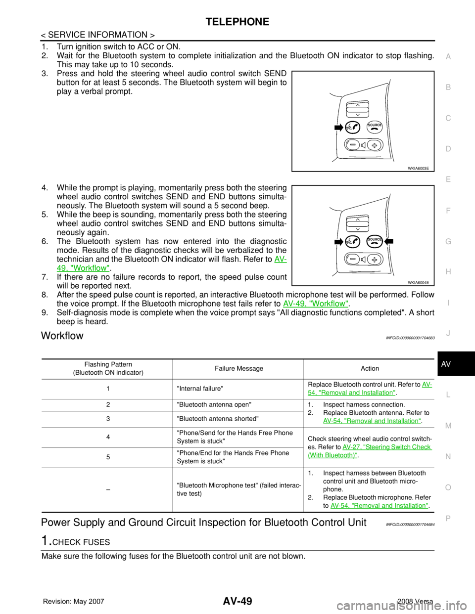
3. Press and hold the steering wheel audio control switch SEND
button for at least 5 seconds. The Bluetooth system will begin to
play a verbal prompt.
4. While the prompt is playing, momentarily press both the steering
wheel audio control switches SEND and END buttons simulta-
neously. The Bluetooth system will sound a 5 second beep.
5. While the beep is sounding, momentarily press both the steering
wheel audio control switches SEND and END buttons simulta-
neously again.
6. The Bluetooth system has now entered into the diagnostic
mode. Results of the diagnostic checks will be verbalized to the
technician and the Bluetooth ON indicator will flash. Refer to AV-
49, "Workflow".
7. If there are no failure records to report, the speed pulse count
will be reported next.
8. After the speed pulse count is reported, an interactive Bluetooth microphone test will be performed. Follow
the voice prompt. If the Bluetooth microphone test fails refer to AV-49, "
Workflow".
9. Self-diagnosis mode is complete when the voice prompt says "All diagnostic functions completed". A short
beep is heard.
WorkflowINFOID:0000000001704683
Power Supply and Ground Circuit Inspection for Bluetooth Control UnitINFOID:0000000001704684
1.CHECK FUSES
Make sure the following fuses for the Bluetooth control unit are not blown.
WKIA6003E
WKIA6004E
Flashing Pattern
(Bluetooth ON indicator)Failure Message Action
1 "Internal failure"Replace Bluetooth control unit. Refer to AV-
54, "Removal and Installation".
2 "Bluetooth antenna open" 1. Inspect harness connection.
2. Replace Bluetooth antenna. Refer to
AV- 5 4 , "
Removal and Installation". 3 "Bluetooth antenna shorted"
4"Phone/Send for the Hands Free Phone
System is stuck"Check steering wheel audio control switch-
es. Refer to AV- 2 7 , "
Steering Switch Check
(With Bluetooth)".
5"Phone/End for the Hands Free Phone
System is stuck"
–"Bluetooth Microphone test" (failed interac-
tive test)1. Inspect harness between Bluetooth
control unit and Bluetooth micro-
phone.
2. Replace Bluetooth microphone. Refer
to AV- 5 4 , "
Removal and Installation".
Page 409 of 2771
AV-50
< SERVICE INFORMATION >
TELEPHONE
OK or NG
OK >> GO TO 2.
NG >> If fuse is blown, be sure to eliminate cause of malfunction before installing new fuse. Refer to PG-
3.
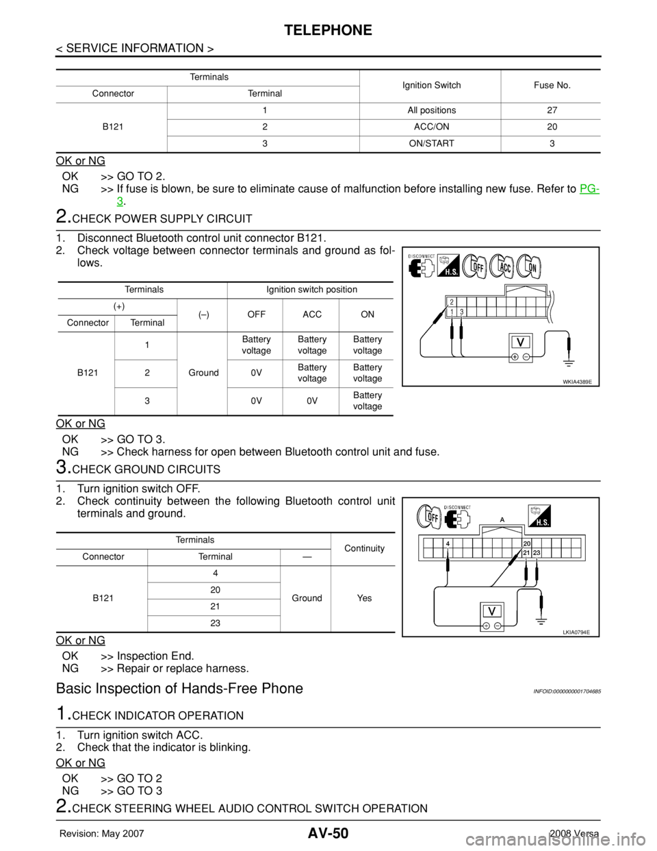
2.CHECK POWER SUPPLY CIRCUIT
1. Disconnect Bluetooth control unit connector B121.
2. Check voltage between connector terminals and ground as fol-
lows.
OK or NG
OK >> GO TO 3.
NG >> Check harness for open between Bluetooth control unit and fuse.
3.CHECK GROUND CIRCUITS
1. Turn ignition switch OFF.
2. Check continuity between the following Bluetooth control unit
terminals and ground.
OK or NG
OK >> Inspection End.
NG >> Repair or replace harness.
Basic Inspection of Hands-Free PhoneINFOID:0000000001704685
1.CHECK INDICATOR OPERATION
1. Turn ignition switch ACC.
2. Check that the indicator is blinking.
OK or NG
OK >> GO TO 2
NG >> GO TO 3
2.CHECK STEERING WHEEL AUDIO CONTROL SWITCH OPERATION
Te r m i n a l s
Ignition Switch Fuse No.
Connector Terminal
B1211 All positions 27
2 ACC/ON 20
3 ON/START 3
Terminals Ignition switch position
(+)
(–) OFF ACC ON
Connector Terminal
B1211
GroundBattery
voltageBattery
voltageBattery
voltage
20VBattery
voltageBattery
voltage
30V0VBattery
voltage
WKIA4389E
Te r m i n a l s
Continuity
Connector Terminal —
B1214
Ground Yes 20
21
23
LKIA0794E
Page 410 of 2771
TELEPHONE
AV-51
< SERVICE INFORMATION >
C
D
E
F
G
H
I
J
L
MA
B
AV
N
O
P
1. Press the SEND switch.
2. Check the indicator is blinking.
OK or NG
OK >> INSPECTION END
NG >> Check steering wheel audio control switch circuit.
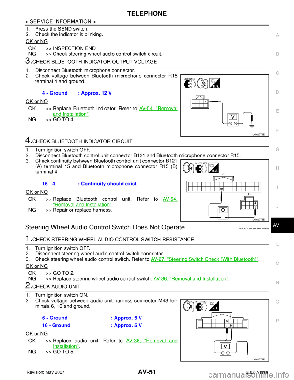
3.CHECK BLUETOOTH INDICATOR OUTPUT VOLTAGE
1. Disconnect Bluetooth microphone connector.
2. Check voltage between Bluetooth microphone connector R15
terminal 4 and ground.
OK or NO
OK >> Replace Bluetooth indicator. Refer to AV-54, "Removal
and Installation".
NG >> GO TO 4.
4.CHECK BLUETOOTH INDICATOR CIRCUIT
1. Turn ignition switch OFF.
2. Disconnect Bluetooth control unit connector B121 and Bluetooth microphone connector R15.
3. Check continuity between Bluetooth control unit connector B121
(A) terminal 15 and Bluetooth microphone connector R15 (B)
terminal 4.
OK or NO
OK >> Replace Bluetooth control unit. Refer to AV-54,
"Removal and Installation".
NG >> Repair or replace harness.
Steering Wheel Audio Control Switch Does Not OperateINFOID:0000000001704686
1.CHECK STEERING WHEEL AUDIO CONTROL SWITCH RESISTANCE
1. Turn ignition switch OFF.
2. Disconnect steering wheel audio control switch connector.
3. Check steering wheel audio control switch. Refer to AV-27, "
Steering Switch Check (With Bluetooth)".
OK or NG
OK >> GO TO 2.
NG >> Replace steering wheel audio control switch. AV-36, "
Removal and Installation".
2.CHECK AUDIO UNIT
1. Turn ignition switch ON.
2. Check voltage between audio unit harness connector M43 ter-
minals 6, 16 and ground.
OK or NG
OK >> Replace audio unit. Refer to AV-36, "Removal and
Installation".
NG >> GO TO 5.4 - Ground : Approx. 12 V
LKIA0774E
15 - 4 : Continuity should exist
LKIA0775E
6 - Ground : Approx. 5 V
16 - Ground : Approx. 5 V
LKIA0776E
Page 423 of 2771

BCM (BODY CONTROL MODULE)
BCS-7
< SERVICE INFORMATION >
C
D
E
F
G
H
I
J
L
MA
B
BCS
N
O
P
CAN Communication System DescriptionINFOID:0000000001704585
Refer to LAN-6, "System Description".
Panic alarm• Key switch
•KeyfobIPDM E/R
Vehicle security system• All door switches
•Keyfob
• Door lock/unlock switch
• Trunk key cylinder switch (Se-
dan)
• Front door key cylinder switch
LH• IPDM/ER
• Security indicator lamp
Battery saver control• Ignition switch
• Combination switchIPDM E/R
Headlamp Combination switch IPDM E/R
Tail lamp Combination switch IPDM E/R
Front fog lamp Combination switch IPDM E/R
Turn signal lamp Combination switch• Turn signal lamp
• Combination meter
Hazard lamp Hazard switch• Turn signal lamp
• Combination meter
Room lamp timer• Key switch
•Keyfob
• Main power window and door
lock/unlock switch
• Front door switch LH
• All door switchInterior room lamp
Back door switch signal (Hatchback) Back door lock assembly Luggage room lamp
Back door lock signal (Hatchback) Back door lock assembly Back door opener
Trunk lamp switch signalTrunk lamp switch and trunk re-
lease solenoidLuggage room lamp
Trunk lid opener signalTrunk lamp switch and trunk re-
lease solenoidTrunk lid opener
Key warning chime• Key switch
• Front door switch LHCombination meter (warning buzzer)
Light warning chime• Combination switch
• Key switch
• Front door switch LHCombination meter (warning buzzer)
Seat belt warning chime• Seat belt buckle switch LH
• Ignition switchCombination meter (warning buzzer)
Front wiper and washer system• Combination switch
• Ignition switchIPDM E/R
Rear window defogger Rear window defogger switch IPDM E/R
Rear wiper and washer system• Combination switch
• Ignition switchRear wiper motor
A/C switch signal Front air control ECM
Blower fan switch signal Front air control ECM
A/C indicator signal Front air control A/C indicator
Low tire pressure warning system Remote keyless entry receiver Combination meterSystem Input Output
Page 428 of 2771

BCS-12
< SERVICE INFORMATION >
BCM (BODY CONTROL MODULE)
18 VRemote keyless entry
receiver (ground)Output OFF — 0V
19 BRRemote keyless entry
receiver (power sup-
ply)Output OFF Ignition switch OFF
20 GRemote keyless entry
receiver signal (signal)Input OFFStand-by (keyfob buttons re-
leased)
When remote keyless entry
receiver receives signal from
keyfob (keyfob buttons
pressed)
21 P NATS antenna amp.Input/
OutputOFF →
ONIgnition switch (OFF → ON)Just after turning ignition switch
ON: Pointer of tester should
move for approx. 1 second, then
return to battery voltage.
23 RSecurity indicator
lampOutput OFFGoes OFF → illuminates (Ev-
ery 2.4 seconds)Battery voltage → 0V
25 LG NATS antenna amp.Input/
OutputOFF →
ONIgnition switch (OFF → ON)Just after turning ignition switch
ON: Pointer of tester should
move for approx. 1 second, then
return to battery voltage.
26 GR Thermo control amp. Input ON A/C switch ON
27 OCompressor ON sig-
nalInput ONA/C switch OFF 5V
A/C switch ON 0V
28 P Front blower monitor Input ONFront blower motor OFF Battery voltage
Front blower motor ON 0V
29 L Hazard switch Input OFFON 0V
OFF 5V Te r m i n a lWire
colorSignal nameSignal
input/
outputMeasuring condition
Reference value or waveform
(Approx.) Ignition
switchOperation or condition
LIIA1893E
LIIA1894E
LIIA1895E
ZJIA0719J
Page 430 of 2771
BCS-14
< SERVICE INFORMATION >
BCM (BODY CONTROL MODULE)
44 LG Rear wiper auto stop Input ONRear wiper operating 0
Rear wiper stopped Battery
45 GR Lock switch Input OFFON (lock) 0V
OFF Battery voltage
46 L Unlock switch Input OFFON (unlock) 0V
OFF Battery voltage
47 BR Front door switch LH Input OFFON (open) 0V
OFF (closed) Battery voltage
48 O Rear door switch LH Input OFFON (open) 0V
OFF (closed) Battery voltage
49 P Luggage room lamp Output OFFAny door open (ON) 0V
All doors closed (OFF) Battery voltage
50 SB A/C indicator Output ONA/C OFF 0
A/C ON Battery voltage
53
*4RBack door lock assem-
bly (actuator)Output OFF Back door (open) Battery voltage
53
*5RTrunk lamp switch and
trunk release solenoidOutput OFF Trunk lid (open) Battery voltage
55 VRear wiper motor out-
putOutput ONOFF 0
ON Battery voltage
56 R Battery saver output OutputOFF30 minutes after ignition
switch is turned OFF0V
ON — Battery voltage
57 LG Battery power supply Input OFF — Battery voltage
59 GFront door lock actua-
tor LH (unlock)Output OFFOFF (neutral) 0V
ON (unlock) Battery voltage
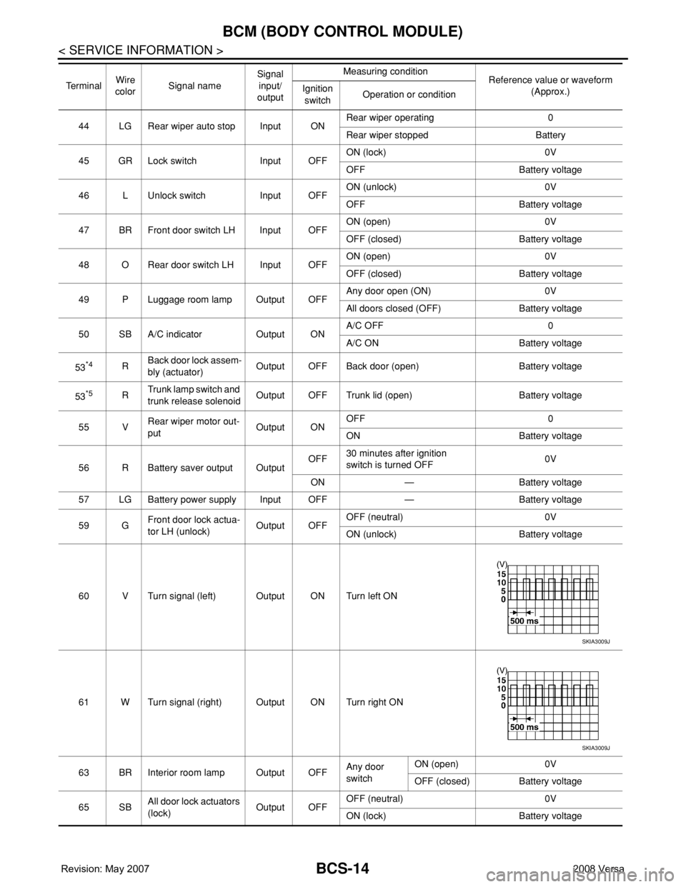
60 V Turn signal (left) Output ON Turn left ON
61 W Turn signal (right) Output ON Turn right ON
63 BR Interior room lamp Output OFFAny door
switchON (open) 0V
OFF (closed) Battery voltage
65 SBAll door lock actuators
(lock)Output OFFOFF (neutral) 0V
ON (lock) Battery voltage Te r m i n a lWire
colorSignal nameSignal
input/
outputMeasuring condition
Reference value or waveform
(Approx.) Ignition
switchOperation or condition
SKIA3009J
SKIA3009J
Page 509 of 2771
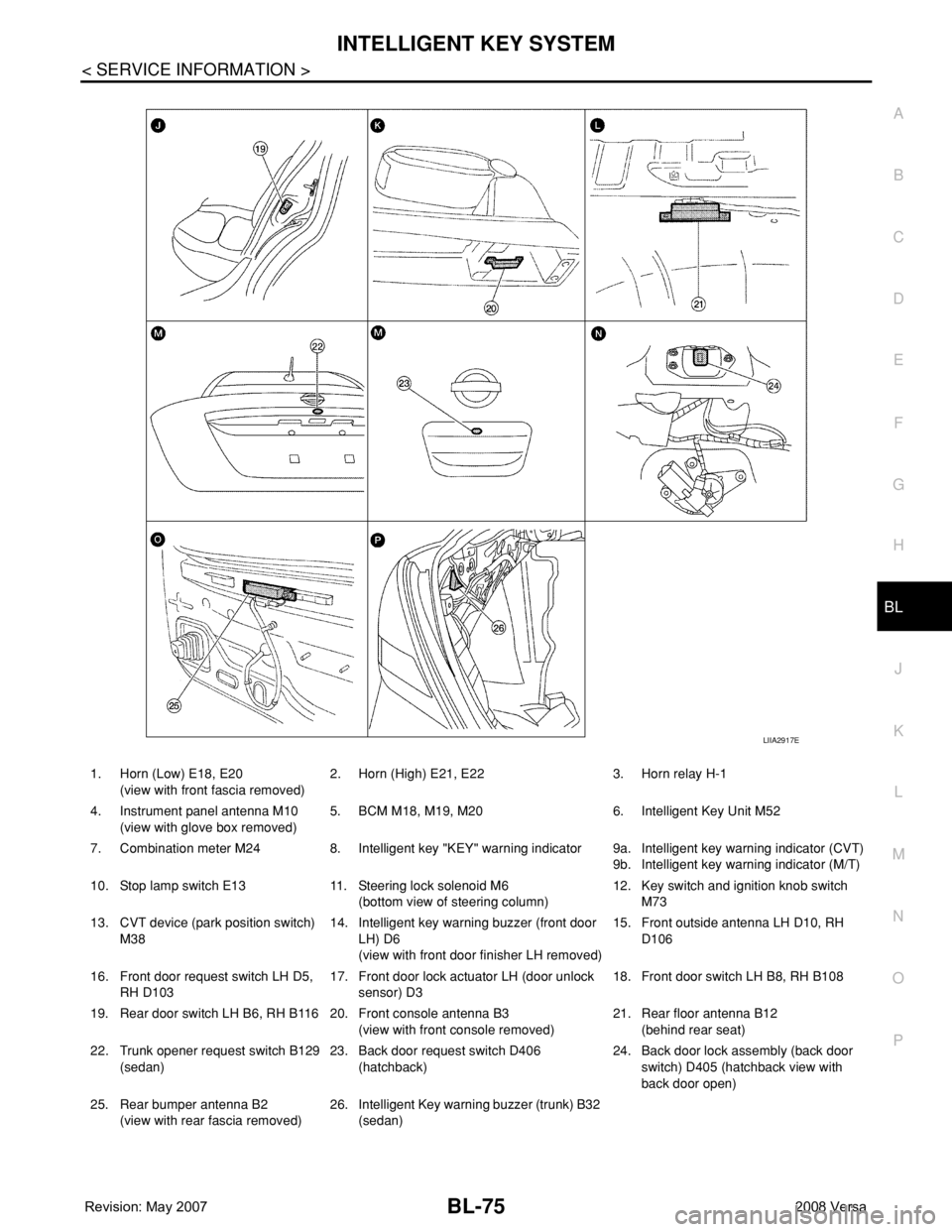
INTELLIGENT KEY SYSTEM
BL-75
< SERVICE INFORMATION >
C
D
E
F
G
H
J
K
L
MA
B
BL
N
O
P
1. Horn (Low) E18, E20
(view with front fascia removed)2. Horn (High) E21, E22 3. Horn relay H-1
4. Instrument panel antenna M10
(view with glove box removed)5. BCM M18, M19, M20 6. Intelligent Key Unit M52
7. Combination meter M24 8. Intelligent key "KEY" warning indicator 9a.
9b.Intelligent key warning indicator (CVT)
Intelligent key warning indicator (M/T)
10. Stop lamp switch E13 11. Steering lock solenoid M6
(bottom view of steering column)12. Key switch and ignition knob switch
M73
13. CVT device (park position switch)
M3814. Intelligent key warning buzzer (front door
LH) D6
(view with front door finisher LH removed)15. Front outside antenna LH D10, RH
D106
16. Front door request switch LH D5,
RH D10317. Front door lock actuator LH (door unlock
sensor) D318. Front door switch LH B8, RH B108
19. Rear door switch LH B6, RH B116 20. Front console antenna B3
(view with front console removed)21. Rear floor antenna B12
(behind rear seat)
22. Trunk opener request switch B129
(sedan)23. Back door request switch D406
(hatchback)24. Back door lock assembly (back door
switch) D405 (hatchback view with
back door open)
25. Rear bumper antenna B2
(view with rear fascia removed)26. Intelligent Key warning buzzer (trunk) B32
(sedan)
LIIA2917E
Page 536 of 2771

BL-102
< SERVICE INFORMATION >
INTELLIGENT KEY SYSTEM
* : Sedan
WORK SUPPORT
Te s t i t e m D e s c r i p t i o n
DOOR LOCK/UNLOCKThis test is able to check door lock/unlock operation.
• The all door lock actuators are unlocked when “ALL UNLK” on CONSULT-III screen is touched.
• The all door lock actuators are locked when “LOCK” on CONSULT-III screen is touched.
ANTENNAThis test is able to check Intelligent Key antenna operation.
When the following conditions are met, hazard warning lamps flash.
• Inside key antenna (front console) detects Intelligent Key, when “ROOM ANT1” on CONSULT-
III screen is touched.
• Inside key antenna (instrument panel and rear floor) detects Intelligent Key, when “ROOM
ANT2” on CONSULT-III screen is touched.
• Outside key antenna (driver side) detects Intelligent Key, when “DRIVER ANT” on CONSULT-III
screen is touched.
• Outside key antenna (passenger side) detects Intelligent Key, when “ASSIST ANT” on CON-
SULT-III screen is touched.
• Outside key antenna (rear bumper) detects Intelligent Key, when “BK DOOR ANT” on CON-
SULT-III screen is touched.
OUTSIDE BUZZER(S)
(DRIVER DOOR), (TRUNK)
*This test is able to check Intelligent Key warning buzzer operation.
Intelligent Key warning buzzer sounds when “ON” on CONSULT-III screen is touched.
INSIDE BUZZER
(CHIME)This test is able to check Intelligent Key warning chime (Instrument panel) operation.
• Take away warning chime sounds when “TAKE OUT” on CONSULT-III screen is touched.
• Ignition switch warning chime sounds when “KNOB” on CONSULT-III screen is touched.
• Ignition key warning chime sounds when “KEY” on CONSULT-III screen is touched.
INDICATORThis test is able to check warning lamp operation.
• “KEY” Warning lamp (Green) illuminates when “BLUE ON” on CONSULT-III screen is touched.
• “KEY” Warning lamp (Red) illuminates when “RED ON” on CONSULT-III screen is touched.
• “LOCK” Warning lamp illuminates when “KNOB ON” on CONSULT-III screen is touched.
• “KEY” Warning lamp (Green) flashes when “BLUE IND” on CONSULT-III screen is touched.
• “KEY” Warning lamp (RED) flashes when “BLUE IND” on CONSULT-III screen is touched.
• “P-SHIFT” Warning lamp flashes when “KNOB ON” on CONSULT-III screen is touched.
Monitor item Description
CONFIRM KEY FOB ID It can be checked whether Intelligent Key ID code is registered or not in this mode.
TAKE OUT FROM WINDOW
WARNTake away warning chime (from window) mode can be changed to operate (ON) or not operate
(OFF) with this mode. The operation mode will be changed when “CHANGE SETT” on CONSULT-
III screen is touched.
LOW BAT OF KEY FOB WARNIntelligent Key low battery warning mode can be changed to operate (ON) or not operate (OFF)
with this mode. The operation mode will be changed when “CHANGE SETT” on CONSULT-III
screen is touched.
ANSWER BACK FUNCTIONBuzzer reminder function mode by Intelligent button can be changed to operate (ON) or not oper-
ate (OFF) with this mode. The operation mode will be changed when “CHANGE SETT” on CON-
SULT-III screen is touched.
SELECTIVE UNLOCK FUNC-
TIONSelective unlock function mode can be changed to operate (ON) or not operate (OFF) with this
mode. The operation mode will be changed when “CHANGE SETT” on CONSULT-III screen is
touched.
ANTI KEY LOCK IN FUNCTIONKey reminder function mode can be changed to operate (ON) or not operate (OFF) with this mode.
The operation mode will be changed when “CHANGE SETT” on CONSULT-III screen is touched.
HORN WITH KEYLESS LOCKHorn reminder function mode by Intelligent Key remote control button can be changed to operate
(ON) or not operate (OFF) with this mode. The operation mode will be changed when “CHANGE
SETT” on CONSULT-III screen is touched.
HAZARD ANSWER BACKHazard reminder function mode can be selected from the following with this mode. The operation
mode will be changed when “CHANGE SETT” on CONSULT-III screen is touched.
• LOCK ONLY: Door lock operation only
• UNLOCK ONLY: Door unlock operation only
• LOCK/UNLOCK: Lock/Unlock operation
• OFF: Non-operation