2008 NISSAN LATIO ignition
[x] Cancel search: ignitionPage 206 of 2771

AT-194
< SERVICE INFORMATION >
TROUBLE DIAGNOSIS FOR SYMPTOMS
OK or NG
OK >> Go to AT-186, "A/T Does Not Shift: D2→ D3" .
NG >> Check overdrive control switch. Refer to AT-171, "
Component Inspection" .
A/T Does Not Shift: D3→ 22, When Selector Lever "D" → "2" PositionINFOID:0000000001703351
SYMPTOM:
A/T does not shift from D3 to 22 when changing selector lever from “D” to “2” position on “Cruise
Test — Part 3”.
DIAGNOSTIC PROCEDURE
1.CHECK SYMPTOM
Check symptom. Refer to AT-55, "
Cruise Test - Part 1" or AT-58, "Cruise Test - Part 2" .
Is
“A/T Does Not Shift: D1 → D2 or Does Not Kickdown: D4→ D2” OK?
YES (With CONSULT-III) >>GO TO 2.
YES (Without CONSULT-III) >>GO TO 3.
NO >> Go to AT-185, "
A/T Does Not Shift: D1→ D2or Does Not Kickdown: D4→ D2" .
2.CHECK PNP SWITCH CIRCUIT
With CONSULT-III
1. Turn ignition switch ON. (Do not start engine.)
2. Select “TCM INPUT SIGNALS” in “DATA MONITOR” mode for “A/T” with CONSULT-III.
3. Read out “P·N”, “R”, “D”, “2” and “1” position switches moving selector lever to each position.
OK or NG
OK >>INSPECTION END
NG >> Check PNP switch. Refer to AT-171, "
Component Inspection" .
3.CHECK PNP SWITCH CIRCUIT
Without CONSULT-III
1. Turn ignition switch ON. (Do not start engine.)
Monitor item Condition Display value
PN POSI SWWhen setting selector lever to “N” or “P” posi-
tion.ON
When setting selector lever to other positions. OFF
R POSITION SWWhen setting selector lever to “R” position. ON
When setting selector lever to other positions. OFF
D POSITION SWWhen setting selector lever to “D” positions. ON
When setting selector lever to other positions. OFF
2 POSITION SWWhen setting selector lever to “2” position. ON
When setting selector lever to other positions. OFF
1 POSITION SWWhen setting selector lever to “1” position. ON
When setting selector lever to other positions. OFF
Page 207 of 2771
TROUBLE DIAGNOSIS FOR SYMPTOMS
AT-195
< SERVICE INFORMATION >
D
E
F
G
H
I
J
K
L
MA
B
AT
N
O
P
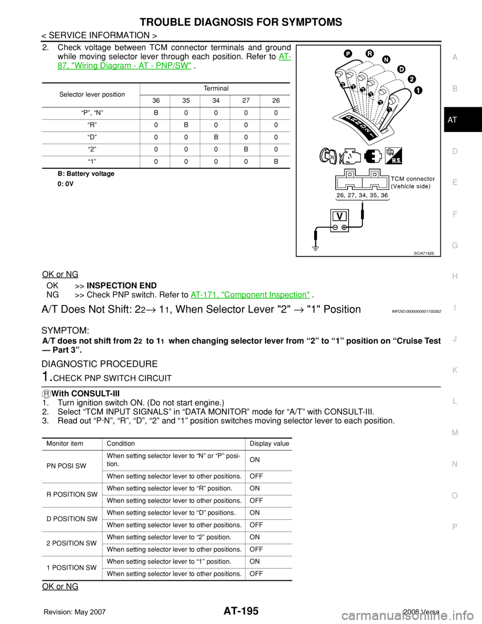
2. Check voltage between TCM connector terminals and ground
while moving selector lever through each position. Refer to AT-
87, "Wiring Diagram - AT - PNP/SW" .
B: Battery voltage
0: 0V
OK or NG
OK >>INSPECTION END
NG >> Check PNP switch. Refer to AT-171, "
Component Inspection" .
A/T Does Not Shift: 22→ 11, When Selector Lever "2" → "1" PositionINFOID:0000000001703352
SYMPTOM:
A/T does not shift from 22 to 11 when changing selector lever from “2” to “1” position on “Cruise Test
— Part 3”.
DIAGNOSTIC PROCEDURE
1.CHECK PNP SWITCH CIRCUIT
With CONSULT-III
1. Turn ignition switch ON. (Do not start engine.)
2. Select “TCM INPUT SIGNALS” in “DATA MONITOR” mode for “A/T” with CONSULT-III.
3. Read out “P·N”, “R”, “D”, “2” and “1” position switches moving selector lever to each position.
OK or NG
Selector lever positionTe r m i n a l
36 35 34 27 26
“P”, “N” B 0 0 0 0
“R” 0B000
“D” 0 0 B 0 0
“2” 0 0 0 B 0
“1” 0 0 0 0 B
SCIA7162E
Monitor item Condition Display value
PN POSI SWWhen setting selector lever to “N” or “P” posi-
tion.ON
When setting selector lever to other positions. OFF
R POSITION SWWhen setting selector lever to “R” position. ON
When setting selector lever to other positions. OFF
D POSITION SWWhen setting selector lever to “D” positions. ON
When setting selector lever to other positions. OFF
2 POSITION SWWhen setting selector lever to “2” position. ON
When setting selector lever to other positions. OFF
1 POSITION SWWhen setting selector lever to “1” position. ON
When setting selector lever to other positions. OFF
Page 208 of 2771
AT-196
< SERVICE INFORMATION >
TROUBLE DIAGNOSIS FOR SYMPTOMS
OK >> GO TO 3
NG >> Check PNP switch. Refer to AT-171, "
Component Inspection" .
2.CHECK PNP SWITCH CIRCUIT
Without CONSULT-III
1. Turn ignition switch ON. (Do not start engine.)
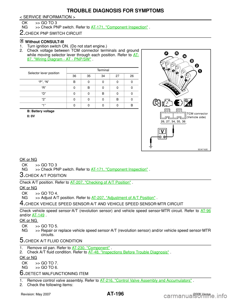
2. Check voltage between TCM connector terminals and ground
while moving selector lever through each position. Refer to AT-
87, "Wiring Diagram - AT - PNP/SW" .
B: Battery voltage
0: 0V
OK or NG
OK >> GO TO 3
NG >> Check PNP switch. Refer to AT-171, "
Component Inspection" .
3.CHECK A/T POSITION
Check A/T position. Refer to AT-207, "
Checking of A/T Position" .
OK or NG
OK >> GO TO 4.
NG >> Adjust A/T position. Refer to AT-207, "
Adjustment of A/T Position" .
4.CHECK VEHICLE SPEED SENSOR·A/T AND VEHICLE SPEED SENSOR·MTR CIRCUIT
Check vehicle speed sensor·A/T (revolution sensor) and vehicle speed sensor·MTR circuit. Refer to AT- 9 6
and/or AT-149 .
OK or NG
OK >> GO TO 5.
NG >> Repair or replace vehicle speed sensor·A/T (revolution sensor) and/or vehicle speed sensor·MTR
circuits.
5.CHECK A/T FLUID CONDITION
1. Remove oil pan. Refer to AT-230, "
Component" .
2. Check A/T fluid condition. Refer to AT-48, "
Inspections Before Trouble Diagnosis" .
OK or NG
OK >> GO TO 7.
NG >> GO TO 6.
6.DETECT MALFUNCTIONING ITEM
1. Remove control valve assembly. Refer to AT-216, "
Control Valve Assembly and Accumulators" .
2. Check the following items:
Selector lever positionTe r m i n a l
36 35 34 27 26
“P”, “N” B0000
“R” 0B000
“D” 0 0 B 0 0
“2” 000B0
“1” 0000B
SCIA7162E
Page 209 of 2771
TROUBLE DIAGNOSIS FOR SYMPTOMS
AT-197
< SERVICE INFORMATION >
D
E
F
G
H
I
J
K
L
MA
B
AT
N
O
P
- Shift valve A
- Shift solenoid valve A
- Overrun clutch control valve
- Overrun clutch solenoid valve
3. Disassemble A/T. Refer to AT-240, "
Disassembly" .
4. Check the following items:
- Servo piston assembly
- Brake band
OK or NG
OK >> GO TO 7.
NG >> Repair or replace damaged parts.
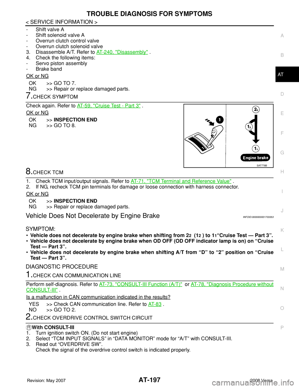
7.CHECK SYMPTOM
Check again. Refer to AT-59, "
Cruise Test - Part 3" .
OK or NG
OK >>INSPECTION END
NG >> GO TO 8.
8.CHECK TCM
1. Check TCM input/output signals. Refer to AT-71, "
TCM Terminal and Reference Value" .
2. If NG, recheck TCM pin terminals for damage or loose connection with harness connector.
OK or NG
OK >>INSPECTION END
NG >> Repair or replace damaged parts.
Vehicle Does Not Decelerate by Engine BrakeINFOID:0000000001703353
SYMPTOM:
•Vehicle does not decelerate by engine brake when shifting from 22 (12 ) to 11“Cruise Test — Part 3”.
•Vehicle does not decelerate by engine brake when OD OFF (OD OFF indicator lamp is on) on “Cruise
Test — Part 3”.
•Vehicle does not decelerate by engine brake when shifting A/T from “D” to “2” position on “Cruise
Test — Part 3”.
DIAGNOSTIC PROCEDURE
1.CHECK CAN COMMUNICATION LINE
Perform self-diagnosis. Refer to AT-73, "
CONSULT-III Function (A/T)" or AT-78, "Diagnosis Procedure without
CONSULT-III" .
Is a malfunction in CAN communication indicated in the results?
YES >> Check CAN communication line. Refer to AT- 8 3 .
NO >> GO TO 2.
2.CHECK OVERDRIVE CONTROL SWITCH CIRCUIT
With CONSULT-III
1. Turn ignition switch ON. (Do not start engine)
2. Select “TCM INPUT SIGNALS” in “DATA MONITOR” mode for “A/T” with CONSULT-III.
3. Read out “OVERDRIVE SW”.
Check the signal of the overdrive control switch is indicated properly.
SAT778B
Page 210 of 2771
AT-198
< SERVICE INFORMATION >
TROUBLE DIAGNOSIS FOR SYMPTOMS
Without CONSULT-III
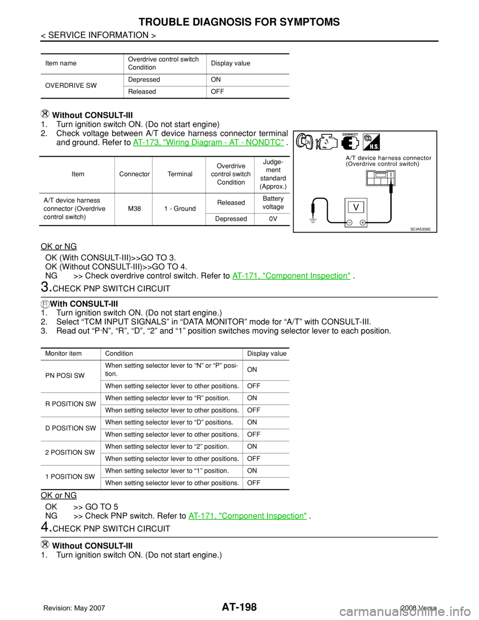
1. Turn ignition switch ON. (Do not start engine)
2. Check voltage between A/T device harness connector terminal
and ground. Refer to AT-173, "
Wiring Diagram - AT - NONDTC" .
OK or NG
OK (With CONSULT-III)>>GO TO 3.
OK (Without CONSULT-III)>>GO TO 4.
NG >> Check overdrive control switch. Refer to AT-171, "
Component Inspection" .
3.CHECK PNP SWITCH CIRCUIT
With CONSULT-III
1. Turn ignition switch ON. (Do not start engine.)
2. Select “TCM INPUT SIGNALS” in “DATA MONITOR” mode for “A/T” with CONSULT-III.
3. Read out “P·N”, “R”, “D”, “2” and “1” position switches moving selector lever to each position.
OK or NG
OK >> GO TO 5
NG >> Check PNP switch. Refer to AT-171, "
Component Inspection" .
4.CHECK PNP SWITCH CIRCUIT
Without CONSULT-III
1. Turn ignition switch ON. (Do not start engine.)
Item nameOverdrive control switch
ConditionDisplay value
OVERDRIVE SWDepressed ON
Released OFF
Item Connector TerminalOverdrive
control switch
ConditionJudge-
ment
standard
(Approx.)
A/T device harness
connector (Overdrive
control switch)M38 1 - GroundReleasedBattery
voltage
Depressed 0V
SCIA5336E
Monitor item Condition Display value
PN POSI SWWhen setting selector lever to “N” or “P” posi-
tion.ON
When setting selector lever to other positions. OFF
R POSITION SWWhen setting selector lever to “R” position. ON
When setting selector lever to other positions. OFF
D POSITION SWWhen setting selector lever to “D” positions. ON
When setting selector lever to other positions. OFF
2 POSITION SWWhen setting selector lever to “2” position. ON
When setting selector lever to other positions. OFF
1 POSITION SWWhen setting selector lever to “1” position. ON
When setting selector lever to other positions. OFF
Page 219 of 2771

SHIFT CONTROL SYSTEM
AT-207
< SERVICE INFORMATION >
D
E
F
G
H
I
J
K
L
MA
B
AT
N
O
P
1. Place the selector lever knob (1) in “N” position.
2. Slide knob cover (2) downward.
3. Pull out lock pin (3) from selector lever knob (1).
4. Remove selector lever knob (1) and knob cover (2) as a set from
selector lever.
CAUTION:
Do not push selector button.
INSTALLATION
1. Insert lock pin (1) to selector lever knob (2).
2. Install knob cover (3) to selector lever knob (2).
3. Place the selector lever in “N” position.
4. Install selector lever knob over selector lever until a click is felt.
CAUTION:
• Do not tilt selector lever knob when installing. Install it
straight, and do not tap or apply any shock to install it.
• Do not push selector button.
Adjustment of A/T PositionINFOID:0000000001703359
Move selector lever from “P” position to “1” position. You should be able to feel the detents in each position. If
the detents cannot be felt or if the position indicator is improperly aligned, the control cable needs adjustment.
CAUTION:
Make sure that parking brake is applied before adjustment.
1. Remove the air duct assembly. Refer to EM-16
.
2. Remove the control cable nut (A) and control cable (1) and
place the manual lever (2) in the "P' position.
3. Place selector lever in “P” position.
4. Hold control cable (1) at the end and pull it with a force of 9.8 N
(approximately 1 kg, 2.2 lb). Release the control cable and tem-
porarily tighten control cable nut (A).
5. Tighten control cable nut (A) to the specified torque.
CAUTION:
Secure manual lever when tightening nut.
6. Move selector lever from “P” to “1” position again. Make sure that selector lever moves smoothly.
7. Check A/T position. Refer to AT-207, "
Checking of A/T Position".
8. Install air duct assembly. Refer to EM-16
.
Checking of A/T PositionINFOID:0000000001703360
1. Place selector lever in “P” position, and turn ignition switch ON (Do not start engine).
2. Make sure selector lever can be shifted to other than “P” position when brake pedal is depressed. Also
make sure selector lever can be shifted from “P” position only when brake pedal is depressed.
3. Move selector lever and check for excessive effort, sticking, noise or rattle.
4. Confirm selector lever stops at each position with the feel of engagement when it is moved through all the
positions. Check whether or not the actual position selector lever is in matches the position shown by the
shift position indicator and the transaxle.
SCIA6971E
SCIA6972E
Control cable nut : Refer to AT-203, "Control De-
vice Removal and Installation".WCIA0635E
Page 221 of 2771
A/T SHIFT LOCK SYSTEM
AT-209
< SERVICE INFORMATION >
D
E
F
G
H
I
J
K
L
MA
B
AT
N
O
P
A/T SHIFT LOCK SYSTEM
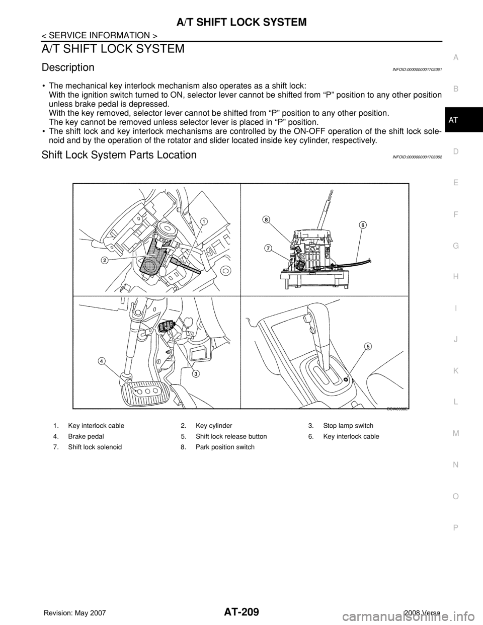
DescriptionINFOID:0000000001703361
• The mechanical key interlock mechanism also operates as a shift lock:
With the ignition switch turned to ON, selector lever cannot be shifted from “P” position to any other position
unless brake pedal is depressed.
With the key removed, selector lever cannot be shifted from “P” position to any other position.
The key cannot be removed unless selector lever is placed in “P” position.
• The shift lock and key interlock mechanisms are controlled by the ON-OFF operation of the shift lock sole-
noid and by the operation of the rotator and slider located inside key cylinder, respectively.
Shift Lock System Parts LocationINFOID:0000000001703362
1. Key interlock cable 2. Key cylinder 3. Stop lamp switch
4. Brake pedal 5. Shift lock release button 6. Key interlock cable
7. Shift lock solenoid 8. Park position switch
BCIA0038E
Page 222 of 2771
AT-210
< SERVICE INFORMATION >
A/T SHIFT LOCK SYSTEM
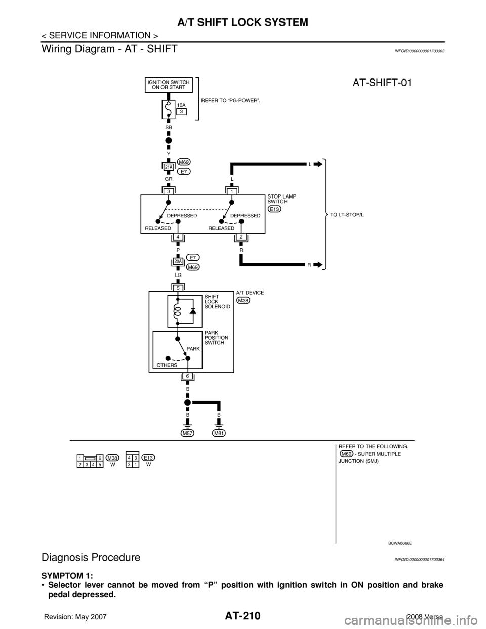
Wiring Diagram - AT - SHIFT
INFOID:0000000001703363
Diagnosis ProcedureINFOID:0000000001703364
SYMPTOM 1:
•Selector lever cannot be moved from “P” position with ignition switch in ON position and brake
pedal depressed.
BCWA0666E