Page 1587 of 2771
ASCD BRAKE SWITCH
EC-513
< SERVICE INFORMATION >
C
D
E
F
G
H
I
J
K
L
MA
EC
N
P O
Refer to EC-445, "Component Inspection".
OK or NG
OK >> GO TO 15.
NG >> Replace ASCD brake switch.
9.CHECK ASCD CLUTCH SWITCH INPUT SIGNAL CIRCUIT FOR OPEN AND SHORT
1. Turn ignition switch OFF.
2. Disconnect ECM harness connector.
3. Check harness continuity between ECM terminal 100 and ASCD clutch switch terminal 2.
Refer to Wiring Diagram.
4. Also check harness for short to ground and short to power.
OK or NG
OK >> GO TO 10.
NG >> Repair open circuit or short to ground or short to power in harness or connectors.
10.CHECK ASCD CLUTCH SWITCH
Refer to EC-445, "
Component Inspection"
OK or NG
OK >> GO TO 15.
NG >> Replace ASCD clutch switch.
11 .CHECK STOP LAMP SWITCH POWER SUPPLY CIRCUIT
1. Turn ignition switch OFF.
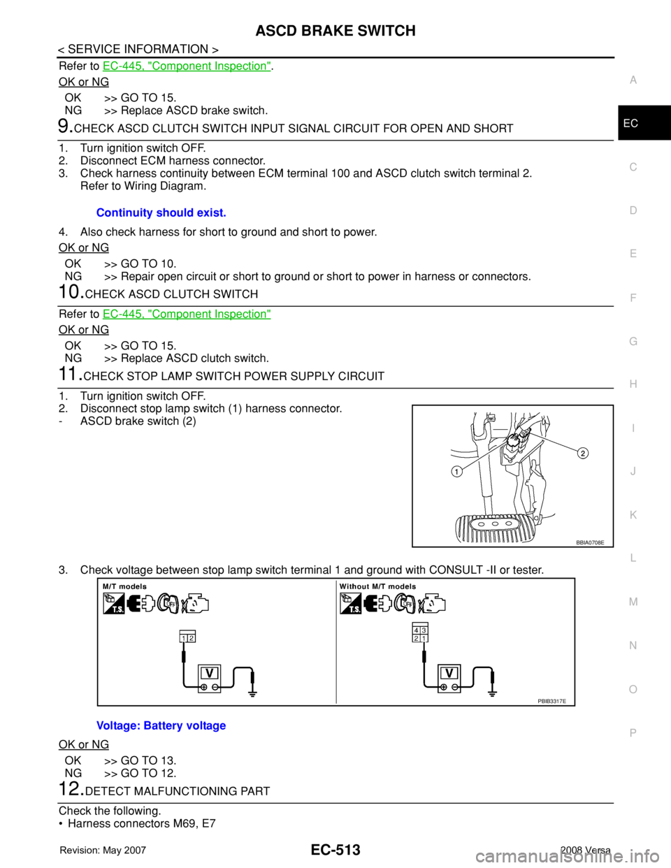
2. Disconnect stop lamp switch (1) harness connector.
- ASCD brake switch (2)
3. Check voltage between stop lamp switch terminal 1 and ground with CONSULT -II or tester.
OK or NG
OK >> GO TO 13.
NG >> GO TO 12.
12.DETECT MALFUNCTIONING PART
Check the following.
• Harness connectors M69, E7Continuity should exist.
BBIA0708E
Voltage: Battery voltage
PBIB3317E
Page 1588 of 2771
EC-514
< SERVICE INFORMATION >
ASCD BRAKE SWITCH
• Harness for open or short between stop lamp switch and battery
>> Repair open circuit or short to ground or short to power in harness or connectors.
13.CHECK STOP LAMP SWITCH INPUT SIGNAL CIRCUIT FOR OPEN AND SHORT
1. Disconnect ECM harness connector.
2. Check harness continuity between ECM terminal 99 and stop lamp switch terminal 2.
Refer to Wiring Diagram.
3. Also check harness for short to ground and short to power.
OK or NG
OK >> GO TO 14.
NG >> Repair open circuit or short to ground or short to power in harness or connectors.
14.CHECK STOP LAMP SWITCH
Refer to EC-445, "
Component Inspection".
OK or NG
OK >> GO TO 15.
NG >> Replace stop lamp switch.
15.CHECK INTERMITTENT INCIDENT
Refer to EC-136
.
>>INSPECTION END
Component InspectionINFOID:0000000001703052
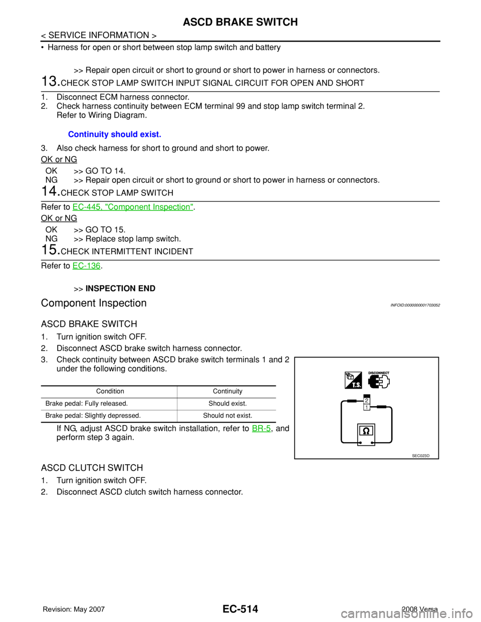
ASCD BRAKE SWITCH
1. Turn ignition switch OFF.
2. Disconnect ASCD brake switch harness connector.
3. Check continuity between ASCD brake switch terminals 1 and 2
under the following conditions.
If NG, adjust ASCD brake switch installation, refer to BR-5
, and
perform step 3 again.
ASCD CLUTCH SWITCH
1. Turn ignition switch OFF.
2. Disconnect ASCD clutch switch harness connector.Continuity should exist.
Condition Continuity
Brake pedal: Fully released. Should exist.
Brake pedal: Slightly depressed. Should not exist.
SEC023D
Page 1589 of 2771
ASCD BRAKE SWITCH
EC-515
< SERVICE INFORMATION >
C
D
E
F
G
H
I
J
K
L
MA
EC
N
P O
3. Check continuity between ASCD clutch switch terminals 1 and 2
under the following conditions.
If NG, adjust ASCD clutch switch installation, refer to CL-5
, and
perform step 3 again.
STOP LAMP SWITCH
1. Turn ignition switch OFF.
2. Disconnect stop lamp switch harness connector.
3. Check continuity between stop lamp switch terminals 1 and 2 under the following conditions.
If NG, adjust stop lamp switch installation, refer to BR-5
, and perform step 3 again.
Condition Continuity
Clutch pedal: Fully released. Should exist.
Clutch pedal: Slightly depressed. Should not exist.
SEC023D
Condition Continuity
Brake pedal: Fully released. Should not exist.
Brake pedal: Slightly depressed. Should exist.
PBIB3318E
Page 1590 of 2771

EC-516
< SERVICE INFORMATION >
ASCD INDICATOR
ASCD INDICATOR
Component DescriptionINFOID:0000000001703053
ASCD indicator lamp illuminates to indicate ASCD operation status. Lamp has two indicators, CRUISE and
SET, and is integrated in combination meter.
CRUISE indicator illuminates when MAIN switch on ASCD steering switch is turned ON to indicate that ASCD
system is ready for operation.
SET indicator illuminates when following conditions are met.
• CRUISE indicator is illuminated.
• SET/COAST switch on ASCD steering switch is turned ON while vehicle speed is within the range of ASCD
setting.
SET indicator remains lit during ASCD control.
Refer to EC-28
for the ASCD function.
CONSULT-II Reference Value in Data Monitor ModeINFOID:0000000001703054
Specification data are reference value.
MONITOR ITEM CONDITION SPECIFICATION
CRUISE LAMP • Ignition switch: ONMAIN switch: Pressed at 1st time
→ 2ndON → OFF
SET LAMP• MAIN switch: ON
• Vehicle: Between 40 km/h (25
MPH) and 144 km/h (89 MPH)ASCD: Operating ON
ASCD: Not operating OFF
Page 1592 of 2771
EC-518
< SERVICE INFORMATION >
ASCD INDICATOR
OK or NG
OK >>INSPECTION END
NG >> GO TO 2.
2.CHECK DTC
Check that DTC U1000 or U1001 is not displayed.
Ye s o r N o
Yes >> Perform trouble diagnoses for DTC U1000, U1001, refer to EC-143.
No >> GO TO 3.
3.CHECK COMBINATION METER OPERATION
Does combination meter operate normally?
Ye s o r N o
Ye s > > G O T O 4 .
No >> Check combination meter circuit. Refer to DI-4
.
4.CHECK INTERMITTENT INCIDENT
Refer to EC-136
.
>>INSPECTION END
ASCD INDICATOR CONDITION SPECIFICATION
CRUISE LAMP • Ignition switch: ONMAIN switch: Pressed at 1st
time → 2ndON → OFF
SET LAMP•MAIN switch: ON
• Vehicle: Between 40 km/h (25
MPH) and 144 km/h (89
MPH)ASCD: Operating ON
ASCD: Not operating OFF
Page 1593 of 2771
ELECTRICAL LOAD SIGNAL
EC-519
< SERVICE INFORMATION >
C
D
E
F
G
H
I
J
K
L
MA
EC
N
P O
ELECTRICAL LOAD SIGNAL
CONSULT-II Reference Value in Data Monitor ModeINFOID:0000000001703057
Specification data are reference values.
Diagnosis ProcedureINFOID:0000000001703058
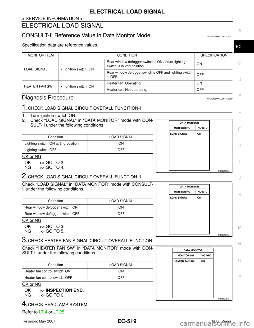
1.CHECK LOAD SIGNAL CIRCUIT OVERALL FUNCITION-I
1. Turn ignition switch ON.
2. Check “LOAD SIGNAL” in “DATA MONITOR” mode with CON-
SULT-II under the following conditions.
OK or NG
OK >> GO TO 2.
NG >> GO TO 4.
2.CHECK LOAD SIGNAL CIRCUIT OVERALL FUNCTION-II
Check “LOAD SIGNAL” in “DATA MONITOR” mode with CONSULT-
II under the following conditions.
OK or NG
OK >> GO TO 3.
NG >> GO TO 5.
3.CHECK HEATER FAN SIGNAL CIRCUIT OVERALL FUNCTION
Check “HEATER FAN SW” in “DATA MONITOR” mode with CON-
SULT-II under the following conditions.
OK or NG
OK >>INSPECTION END.
NG >> GO TO 6.
4.CHECK HEADLAMP SYSTEM
Refer to LT- 4
or LT- 2 5.
MONITOR ITEM CONDITION SPECIFICATION
LOAD SIGNAL • Ignition switch: ONRear window defogger switch is ON and/or lighting
switch is in 2nd position.ON
Rear window defogger switch is OFF and lighting switch
is OFF.OFF
HEATER FAN SW • Ignition switch: ONHeater fan: Operating. ON
Heater fan: Not operating. OFF
Condition LOAD SIGNAL
Lighting switch: ON at 2nd position ON
Lighting switch: OFF OFF
PBIB0103E
Condition LOAD SIGNAL
Rear window defogger switch: ON ON
Rear window defogger switch: OFF OFF
PBIB0103E
Condition LOAD SIGNAL
Heater fan control switch: ON ON
Heater fan control switch: OFF OFF
PBIB1995E
Page 1597 of 2771
FUEL INJECTOR
EC-523
< SERVICE INFORMATION >
C
D
E
F
G
H
I
J
K
L
MA
EC
N
P O
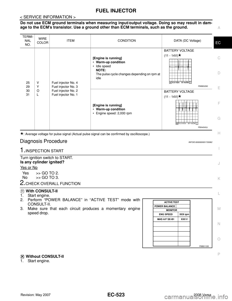
Do not use ECM ground terminals when measuring input/output voltage. Doing so may result in dam-
age to the ECM's transistor. Use a ground other than ECM terminals, such as the ground.
: Average voltage for pulse signal (Actual pulse signal can be confirmed by oscilloscope.)
Diagnosis ProcedureINFOID:0000000001703062
1.INSPECTION START
Turn ignition switch to START.
Is any cylinder ignited?
Ye s o r N o
Yes >> GO TO 2.
No >> GO TO 3.
2.CHECK OVERALL FUNCTION
With CONSULT-II
1. Start engine.
2. Perform “POWER BALANCE” in “ACTIVE TEST” mode with
CONSULT-II.
3. Make sure that each circuit produces a momentary engine
speed drop.
Without CONSULT-II
1. Start engine.
TERMI-
NAL
NO.WIRE
COLORITEM CONDITION DATA (DC Voltage)
25
29
30
31V
Y
O
LFuel injector No. 4
Fuel injector No. 3
Fuel injector No. 2
Fuel injector No. 1[Engine is running]
•Warm-up condition
• Idle speed
NOTE:
The pulse cycle changes depending on rpm at
idleBATTERY VOLTAGE
(11 - 14V)
[Engine is running]
•Warm-up condition
• Engine speed: 2,000 rpmBATTERY VOLTAGE
(11 - 14V)
PBIB0529E
PBIA4943J
PBIB0133E
Page 1598 of 2771
EC-524
< SERVICE INFORMATION >
FUEL INJECTOR
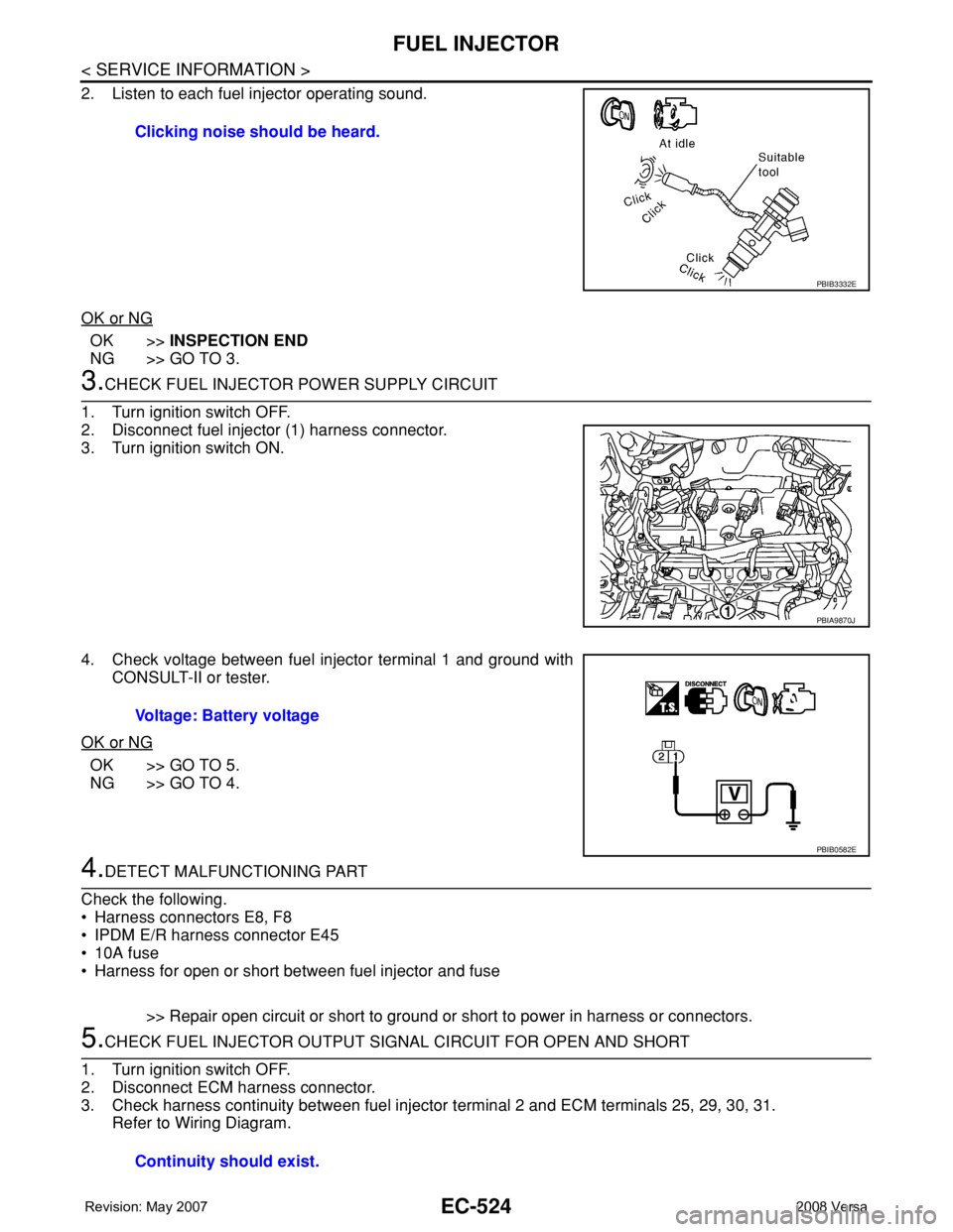
2. Listen to each fuel injector operating sound.
OK or NG
OK >>INSPECTION END
NG >> GO TO 3.
3.CHECK FUEL INJECTOR POWER SUPPLY CIRCUIT
1. Turn ignition switch OFF.
2. Disconnect fuel injector (1) harness connector.
3. Turn ignition switch ON.
4. Check voltage between fuel injector terminal 1 and ground with
CONSULT-II or tester.
OK or NG
OK >> GO TO 5.
NG >> GO TO 4.
4.DETECT MALFUNCTIONING PART
Check the following.
• Harness connectors E8, F8
• IPDM E/R harness connector E45
• 10A fuse
• Harness for open or short between fuel injector and fuse
>> Repair open circuit or short to ground or short to power in harness or connectors.
5.CHECK FUEL INJECTOR OUTPUT SIGNAL CIRCUIT FOR OPEN AND SHORT
1. Turn ignition switch OFF.
2. Disconnect ECM harness connector.
3. Check harness continuity between fuel injector terminal 2 and ECM terminals 25, 29, 30, 31.
Refer to Wiring Diagram.Clicking noise should be heard.
PBIB3332E
PBIA9870J
Voltage: Battery voltage
PBIB0582E
Continuity should exist.