2008 NISSAN LATIO checking oil
[x] Cancel search: checking oilPage 2289 of 2771

MT-1
TRANSMISSION/TRANSAXLE
D
E
F
G
H
I
J
K
L
M
SECTION MT
A
B
MT
N
O
P
CONTENTS
MANUAL TRANSAXLE
SERVICE INFORMATION ............................2
PRECAUTIONS ...................................................2
Precaution for Supplemental Restraint System
(SRS) "AIR BAG" and "SEAT BELT PRE-TEN-
SIONER" ...................................................................
2
Precaution for Procedure without Cowl Top Cover ......2
Precaution .................................................................2
PREPARATION ...................................................3
Special Service Tool .................................................3
Commercial Service Tool ..........................................5
NOISE, VIBRATION AND HARSHNESS
(NVH) TROUBLESHOOTING .............................
7
NVH Troubleshooting Chart ......................................7
DESCRIPTION ....................................................8
Cross-Sectional View ................................................8
M/T OIL ...............................................................10
Changing M/T Oil ....................................................10
Checking M/T Oil .....................................................10
SIDE OIL SEAL ..................................................11
Removal and Installation .........................................11
POSITION SWITCH ............................................12
Checking .................................................................12
CONTROL LINKAGE ........................................13
Component of Control Device and Cable ................13
Removal and Installation .........................................13
AIR BREATHER HOSE ....................................15
Removal and Installation .........................................15
TRANSAXLE ASSEMBLY ................................16
Removal and Installation .........................................16
Disassembly and Assembly .....................................17
INPUT SHAFT AND GEARS ............................35
Disassembly and Assembly .....................................35
MAINSHAFT AND GEARS ...............................39
Disassembly and Assembly .....................................39
REVERSE IDLER SHAFT AND GEARS ..........44
Disassembly and Assembly .....................................44
FINAL DRIVE ....................................................46
Disassembly and Assembly .....................................46
SHIFT CONTROL ..............................................49
Inspection ................................................................49
SERVICE DATA AND SPECIFICATIONS
(SDS) .................................................................
50
General Specification ..............................................50
Page 2298 of 2771
MT-10
< SERVICE INFORMATION >
M/T OIL
M/T OIL
Changing M/T OilINFOID:0000000001703134
DRAINING
1. Start engine and let it run to warm up transaxle.
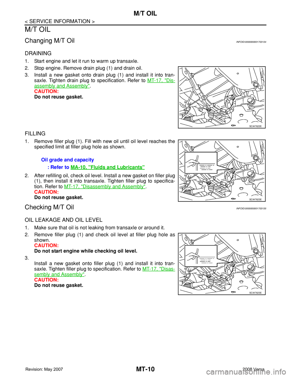
2. Stop engine. Remove drain plug (1) and drain oil.
3. Install a new gasket onto drain plug (1) and install it into tran-
saxle. Tighten drain plug to specification. Refer to MT-17, "
Dis-
assembly and Assembly".
CAUTION:
Do not reuse gasket.
FILLING
1. Remove filler plug (1). Fill with new oil until oil level reaches the
specified limit at filler plug hole as shown.
2. After refilling oil, check oil level. Install a new gasket on filler plug
(1), then install it into transaxle. Tighten filler plug to specifica-
tion. Refer to MT-17, "
Disassembly and Assembly".
CAUTION:
Do not reuse gasket.
Checking M/T OilINFOID:0000000001703135
OIL LEAKAGE AND OIL LEVEL
1. Make sure that oil is not leaking from transaxle or around it.
2. Remove filler plug (1) and check oil level at filler plug hole as
shown.
CAUTION:
Do not start engine while checking oil level.
3.
Install a new gasket onto filler plug (1) and install it into tran-
saxle. Tighten filler plug to specification. Refer to MT-17, "
Disas-
sembly and Assembly".
CAUTION:
Do not reuse gasket.
SCIA7622E
Oil grade and capacity
: Refer to MA-10, "
Fluids and Lubricants"
SCIA7623E
SCIA7623E
Page 2299 of 2771
SIDE OIL SEAL
MT-11
< SERVICE INFORMATION >
D
E
F
G
H
I
J
K
L
MA
B
MT
N
O
P
SIDE OIL SEAL
Removal and InstallationINFOID:0000000001703136
REMOVAL
1. Remove front drive shafts from transaxle assembly. Refer to FA X - 8 , "Removal and Installation (Left
Side)".
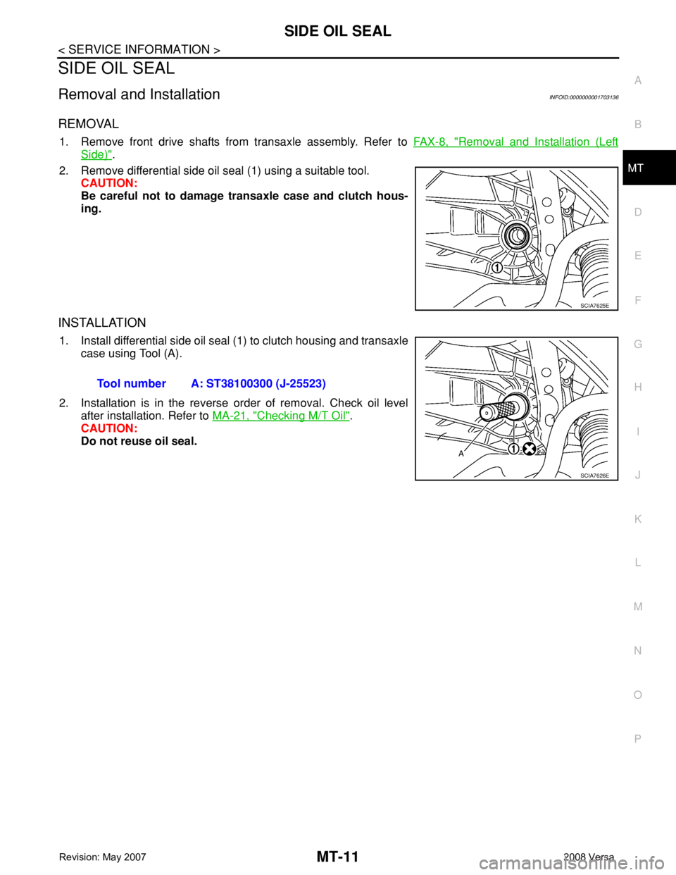
2. Remove differential side oil seal (1) using a suitable tool.
CAUTION:
Be careful not to damage transaxle case and clutch hous-
ing.
INSTALLATION
1. Install differential side oil seal (1) to clutch housing and transaxle
case using Tool (A).
2. Installation is in the reverse order of removal. Check oil level
after installation. Refer to MA-21, "
Checking M/T Oil".
CAUTION:
Do not reuse oil seal.
SCIA7625E
Tool number A: ST38100300 (J-25523)
SCIA7626E
Page 2305 of 2771
TRANSAXLE ASSEMBLY
MT-17
< SERVICE INFORMATION >
D
E
F
G
H
I
J
K
L
MA
B
MT
N
O
P
When installing transaxle assembly, be careful not to bring transaxle input shaft into contact with
clutch cover.
• If transaxle is removed from the vehicle, always replace CSC. Refer to CL-11, "
Removal and Installation".
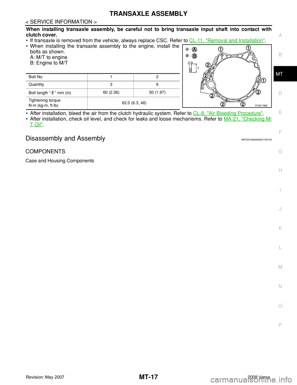
• When installing the transaxle assembly to the engine, install the
bolts as shown.
A: M/T to engine
B: Engine to M/T
• After installation, bleed the air from the clutch hydraulic system. Refer to CL-8, "
Air Bleeding Procedure".
• After installation, check oil level, and check for leaks and loose mechanisms. Refer to MA-21, "
Checking M/
T Oil".
Disassembly and AssemblyINFOID:0000000001703142
COMPONENTS
Case and Housing Components
Bolt No. 1 2
Quantity 3 6
Bolt length “ ” mm (in)60 (2.36) 50 (1.97)
Tightening torque
N·m (kg-m, ft-lb)62.0 (6.3, 46)
PCIB1786E
Page 2340 of 2771

MTC-2
DUCTS AND GRILLES ......................................69
Removal and Installation ........................................69
REFRIGERANT LINES ......................................74
HFC-134a (R-134a) Service Procedure .................74
Component .............................................................76
Removal and Installation of Compressor ................78
Removal and Installation of Low-Pressure Flexi-
ble Hose .................................................................
79
Removal and Installation of High-pressure Flexi-
ble Hose .................................................................
80
Removal and Installation of High-pressure Pipe ....81
Removal and Installation of Refrigerant Pressure
Sensor ....................................................................
81
Removal and Installation of Condenser ..................82
Removal and Installation of Liquid Tank .................82
Removal and Installation of Evaporator ..................83
Removal and Installation of Expansion Valve .........84
Checking of Refrigerant Leaks ................................84
Checking System for Leaks Using the Fluorescent
Leak Detector ..........................................................
85
Dye Injection ...........................................................85
Electronic Refrigerant Leak Detector ......................85
SERVICE DATA AND SPECIFICATIONS
(SDS) .................................................................
88
Compressor ............................................................88
Oil ............................................................................88
Refrigerant ..............................................................88
Engine Idling Speed ................................................88
Belt Tension ............................................................88
Page 2349 of 2771
PREPARATION
MTC-11
< SERVICE INFORMATION >
C
D
E
F
G
H
I
K
L
MA
B
MTC
N
O
P
—
(—)
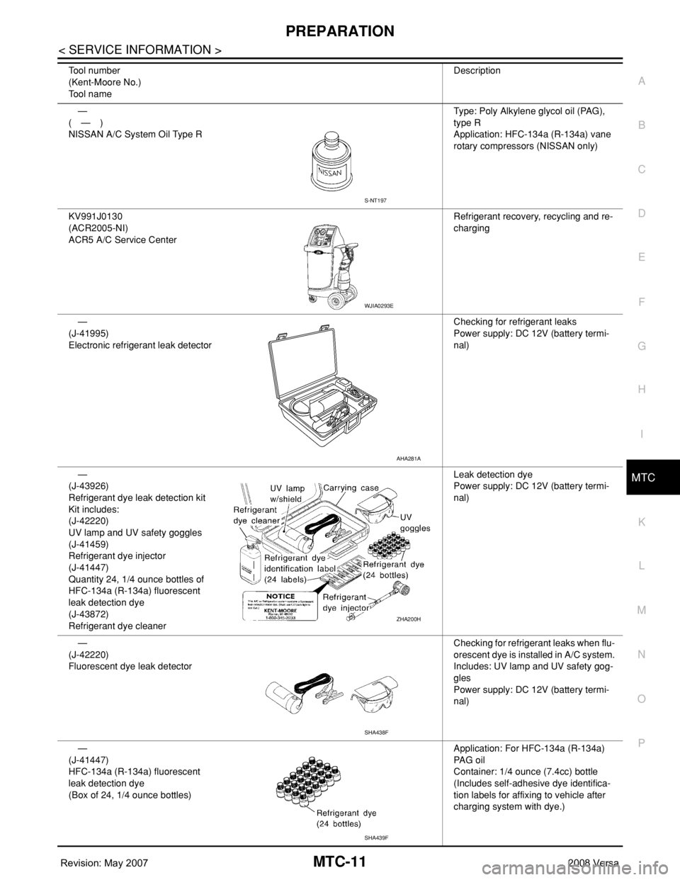
NISSAN A/C System Oil Type RType: Poly Alkylene glycol oil (PAG),
type R
Application: HFC-134a (R-134a) vane
rotary compressors (NISSAN only)
KV991J0130
(ACR2005-NI)
ACR5 A/C Service CenterRefrigerant recovery, recycling and re-
charging
—
(J-41995)
Electronic refrigerant leak detectorChecking for refrigerant leaks
Power supply: DC 12V (battery termi-
nal)
—
(J-43926)
Refrigerant dye leak detection kit
Kit includes:
(J-42220)
UV lamp and UV safety goggles
(J-41459)
Refrigerant dye injector
(J-41447)
Quantity 24, 1/4 ounce bottles of
HFC-134a (R-134a) fluorescent
leak detection dye
(J-43872)
Refrigerant dye cleanerLeak detection dye
Power supply: DC 12V (battery termi-
nal)
—
(J-42220)
Fluorescent dye leak detectorChecking for refrigerant leaks when flu-
orescent dye is installed in A/C system.
Includes: UV lamp and UV safety gog-
gles
Power supply: DC 12V (battery termi-
nal)
—
(J-41447)
HFC-134a (R-134a) fluorescent
leak detection dye
(Box of 24, 1/4 ounce bottles)Application: For HFC-134a (R-134a)
PA G o i l
Container: 1/4 ounce (7.4cc) bottle
(Includes self-adhesive dye identifica-
tion labels for affixing to vehicle after
charging system with dye.) Tool number
(Kent-Moore No.)
Tool nameDescription
S-NT197
WJIA0293E
AHA281A
ZHA200H
SHA438F
SHA439F
Page 2351 of 2771
PREPARATION
MTC-13
< SERVICE INFORMATION >
C
D
E
F
G
H
I
K
L
MA
B
MTC
N
O
P
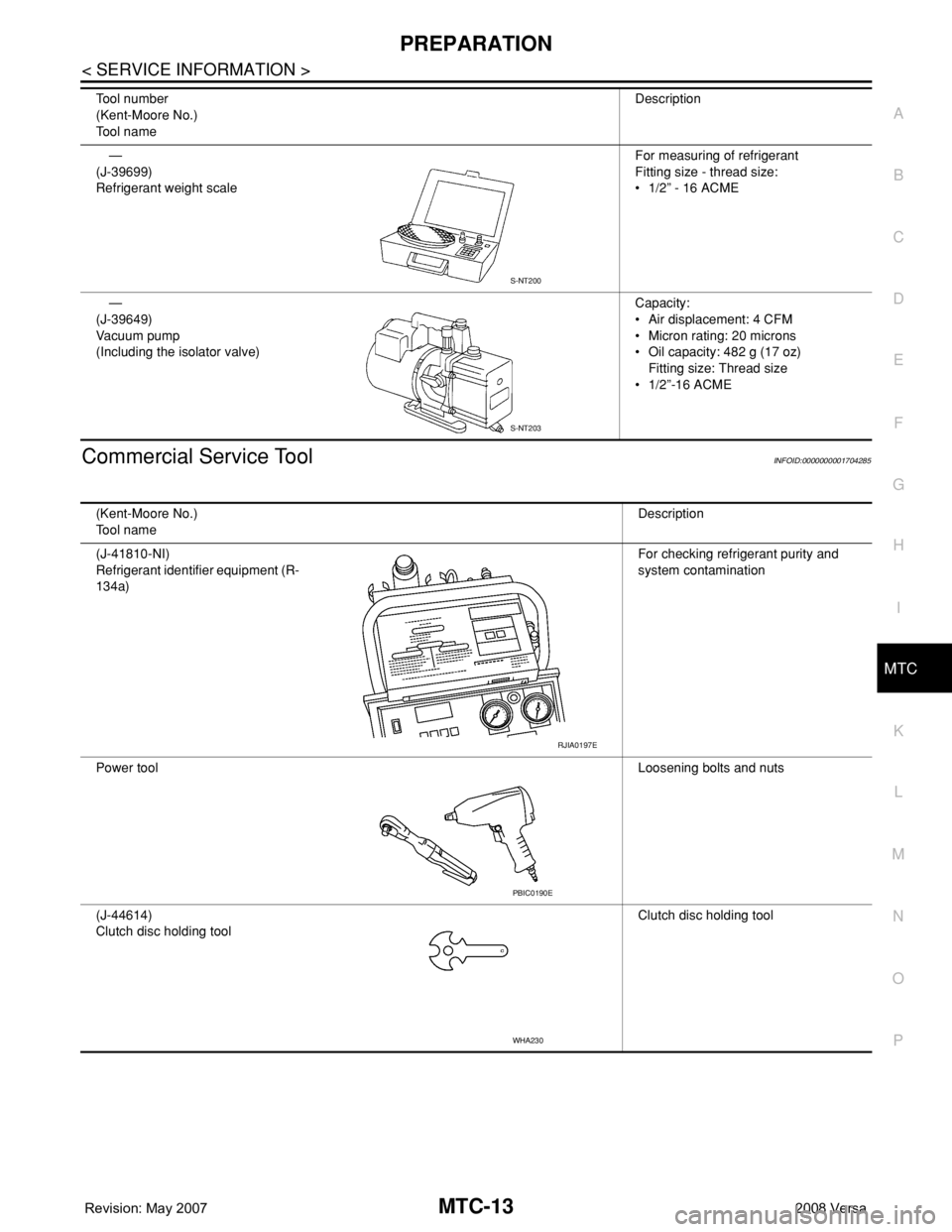
Commercial Service ToolINFOID:0000000001704285
—
(J-39699)
Refrigerant weight scaleFor measuring of refrigerant
Fitting size - thread size:
• 1/2” - 16 ACME
—
(J-39649)
Va c u u m p u m p
(Including the isolator valve)Capacity:
• Air displacement: 4 CFM
• Micron rating: 20 microns
• Oil capacity: 482 g (17 oz)
Fitting size: Thread size
• 1/2”-16 ACME Tool number
(Kent-Moore No.)
Tool nameDescription
S-NT200
S-NT203
(Kent-Moore No.)
Tool nameDescription
(J-41810-NI)
Refrigerant identifier equipment (R-
134a)For checking refrigerant purity and
system contamination
Power toolLoosening bolts and nuts
(J-44614)
Clutch disc holding toolClutch disc holding tool
RJIA0197E
PBIC0190E
WHA230
Page 2389 of 2771
TROUBLE DIAGNOSIS
MTC-51
< SERVICE INFORMATION >
C
D
E
F
G
H
I
K
L
MA
B
MTC
N
O
P Low-pressure Side Sometimes Becomes Negative
Low-pressure Side Becomes Negative
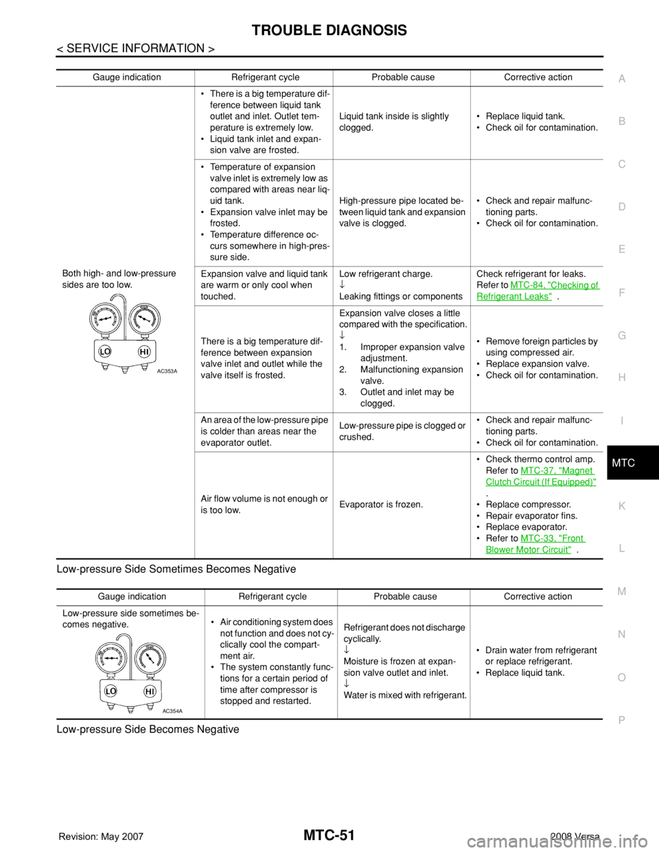
Gauge indication Refrigerant cycle Probable cause Corrective action
Both high- and low-pressure
sides are too low.• There is a big temperature dif-
ference between liquid tank
outlet and inlet. Outlet tem-
perature is extremely low.
• Liquid tank inlet and expan-
sion valve are frosted.Liquid tank inside is slightly
clogged.• Replace liquid tank.
• Check oil for contamination.
• Temperature of expansion
valve inlet is extremely low as
compared with areas near liq-
uid tank.
• Expansion valve inlet may be
frosted.
• Temperature difference oc-
curs somewhere in high-pres-
sure side.High-pressure pipe located be-
tween liquid tank and expansion
valve is clogged.• Check and repair malfunc-
tioning parts.
• Check oil for contamination.
Expansion valve and liquid tank
are warm or only cool when
touched.Low refrigerant charge.
↓
Leaking fittings or componentsCheck refrigerant for leaks.
Refer to MTC-84, "
Checking of
Refrigerant Leaks" .
There is a big temperature dif-
ference between expansion
valve inlet and outlet while the
valve itself is frosted.Expansion valve closes a little
compared with the specification.
↓
1. Improper expansion valve
adjustment.
2. Malfunctioning expansion
valve.
3. Outlet and inlet may be
clogged.• Remove foreign particles by
using compressed air.
• Replace expansion valve.
• Check oil for contamination.
An area of the low-pressure pipe
is colder than areas near the
evaporator outlet.Low-pressure pipe is clogged or
crushed.• Check and repair malfunc-
tioning parts.
• Check oil for contamination.
Air flow volume is not enough or
is too low.Evaporator is frozen.• Check thermo control amp.
Refer to MTC-37, "
Magnet
Clutch Circuit (If Equipped)"
.
• Replace compressor.
• Repair evaporator fins.
• Replace evaporator.
• Refer to MTC-33, "
Front
Blower Motor Circuit" .
AC353A
Gauge indication Refrigerant cycle Probable cause Corrective action
Low-pressure side sometimes be-
comes negative.• Air conditioning system does
not function and does not cy-
clically cool the compart-
ment air.
• The system constantly func-
tions for a certain period of
time after compressor is
stopped and restarted.Refrigerant does not discharge
cyclically.
↓
Moisture is frozen at expan-
sion valve outlet and inlet.
↓
Water is mixed with refrigerant.• Drain water from refrigerant
or replace refrigerant.
• Replace liquid tank.
AC354A