2008 NISSAN LATIO weight
[x] Cancel search: weightPage 2172 of 2771
HEADLAMP (FOR CANADA) - DAYTIME LIGHT SYSTEM -
LT-35
< SERVICE INFORMATION >
C
D
E
F
G
H
I
J
L
MA
B
LT
N
O
P
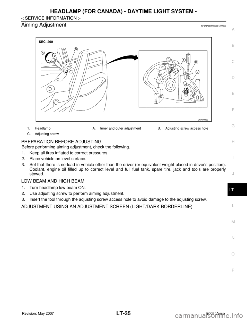
Aiming AdjustmentINFOID:0000000001704393
PREPARATION BEFORE ADJUSTING
Before performing aiming adjustment, check the following.
1. Keep all tires inflated to correct pressures.
2. Place vehicle on level surface.
3. Set that there is no-load in vehicle other than the driver (or equivalent weight placed in driver's position).
Coolant, engine oil filled up to correct level and full fuel tank, spare tire, jack and tools are properly
stowed.
LOW BEAM AND HIGH BEAM
1. Turn headlamp low beam ON.
2. Use adjusting screw to perform aiming adjustment.
3. Insert the tool through the adjusting screw access hole to avoid damage to the adjusting screw.
ADJUSTMENT USING AN ADJUSTMENT SCREEN (LIGHT/DARK BORDERLINE)
1. Headlamp A. Inner and outer adjustment B. Adjusting screw access hole
C. Adjusting screw
LKIA0930E
Page 2183 of 2771
LT-46
< SERVICE INFORMATION >
FRONT FOG LAMP
1. Check continuity between front fog lamp harness connector and
ground.
OK or NG
OK >> Replace IPDM E/R. Refer to PG-26, "Removal and
Installation of IPDM E/R" .
NG >> Repair harness or connector.
Aiming AdjustmentINFOID:0000000001704409
The front fog lamp is a semi-sealed beam type which uses a replaceable halogen bulb. Before performing
aiming adjustment, make sure of the following.
• Keep all tires inflated to correct pressure.
• Place vehicle on level surface.
• Set that there is no-load in vehicle other than the driver (or equivalent weight placed in driver’s position).
Coolant, engine oil filled up to correct level and full fuel tank, spare tire, jack and tools are properly stowed.
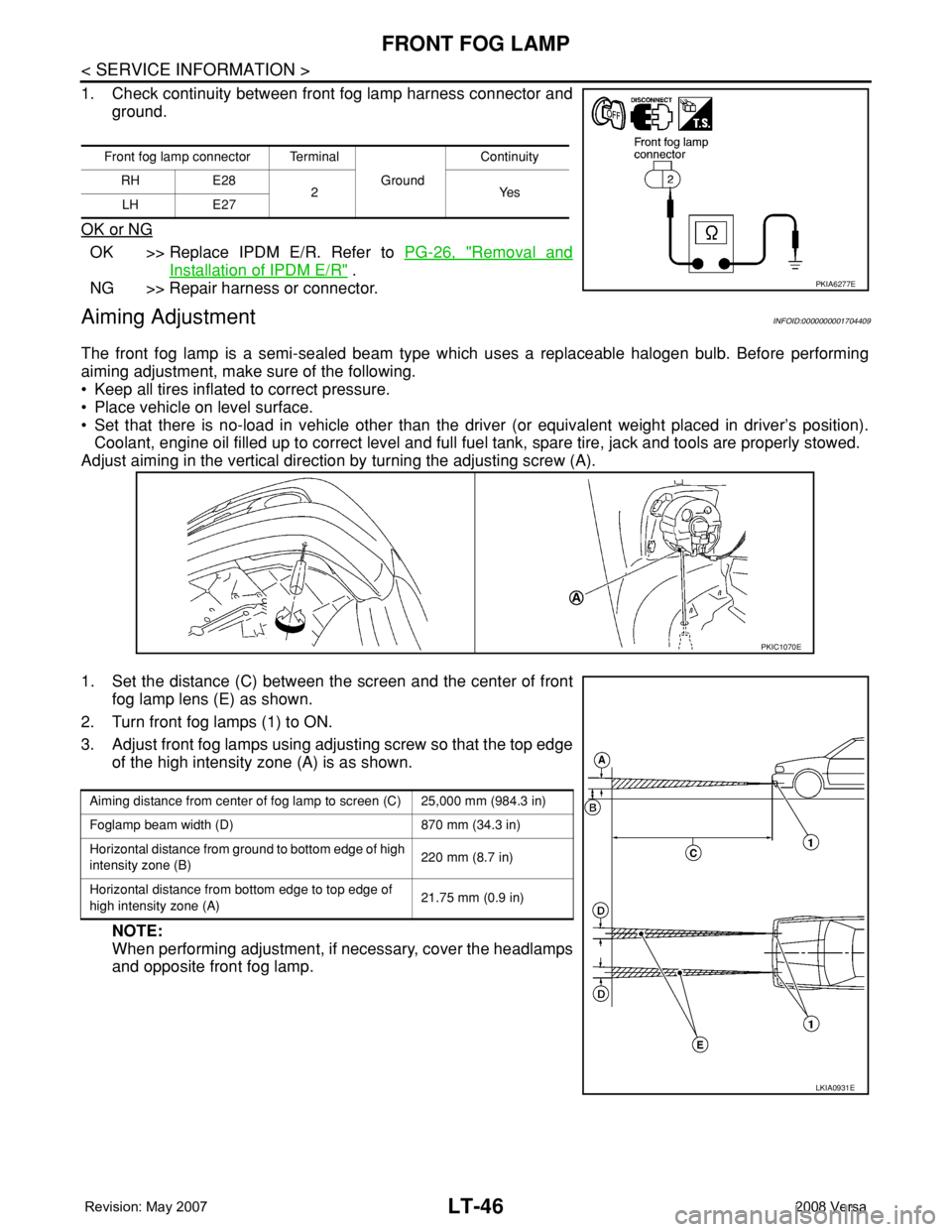
Adjust aiming in the vertical direction by turning the adjusting screw (A).
1. Set the distance (C) between the screen and the center of front
fog lamp lens (E) as shown.
2. Turn front fog lamps (1) to ON.
3. Adjust front fog lamps using adjusting screw so that the top edge
of the high intensity zone (A) is as shown.
NOTE:
When performing adjustment, if necessary, cover the headlamps
and opposite front fog lamp.
Front fog lamp connector Terminal
Ground Continuity
RH E28
2Yes
LH E27
PKIA6277E
PKIC1070E
Aiming distance from center of fog lamp to screen (C) 25,000 mm (984.3 in)
Foglamp beam width (D) 870 mm (34.3 in)
Horizontal distance from ground to bottom edge of high
intensity zone (B)220 mm (8.7 in)
Horizontal distance from bottom edge to top edge of
high intensity zone (A)21.75 mm (0.9 in)
LKIA0931E
Page 2283 of 2771
CHASSIS AND BODY MAINTENANCE
MA-23
< SERVICE INFORMATION >
C
D
E
F
G
H
I
J
K
MA
B
MA
N
O
P
2. Stop engine.
3. Drain A/T fluid by removing the drain plug. Reinstall the drain plug to the specified torque.
CAUTION:
Do not reuse drain plug gasket.
4. Refill the transaxle with new specified A/T fluid through the A/T fluid charging pipe. Always refill the tran-
saxle with the same volume of A/T fluid that was drained out.
5. Run engine at idle speed for 5 minutes.
6. Check A/T fluid level and condition. Refer to MA-22, "
Checking A/T Fluid" .
Balancing WheelsINFOID:0000000001704749
Adjust wheel balance using road wheel center.
CAUTION:
• Be careful not to scratch the road wheel during removal.
• Use clip-on type wheel balance weights only.
Wheel balance (Maximum allowable unbalance):
RotationINFOID:0000000001704750
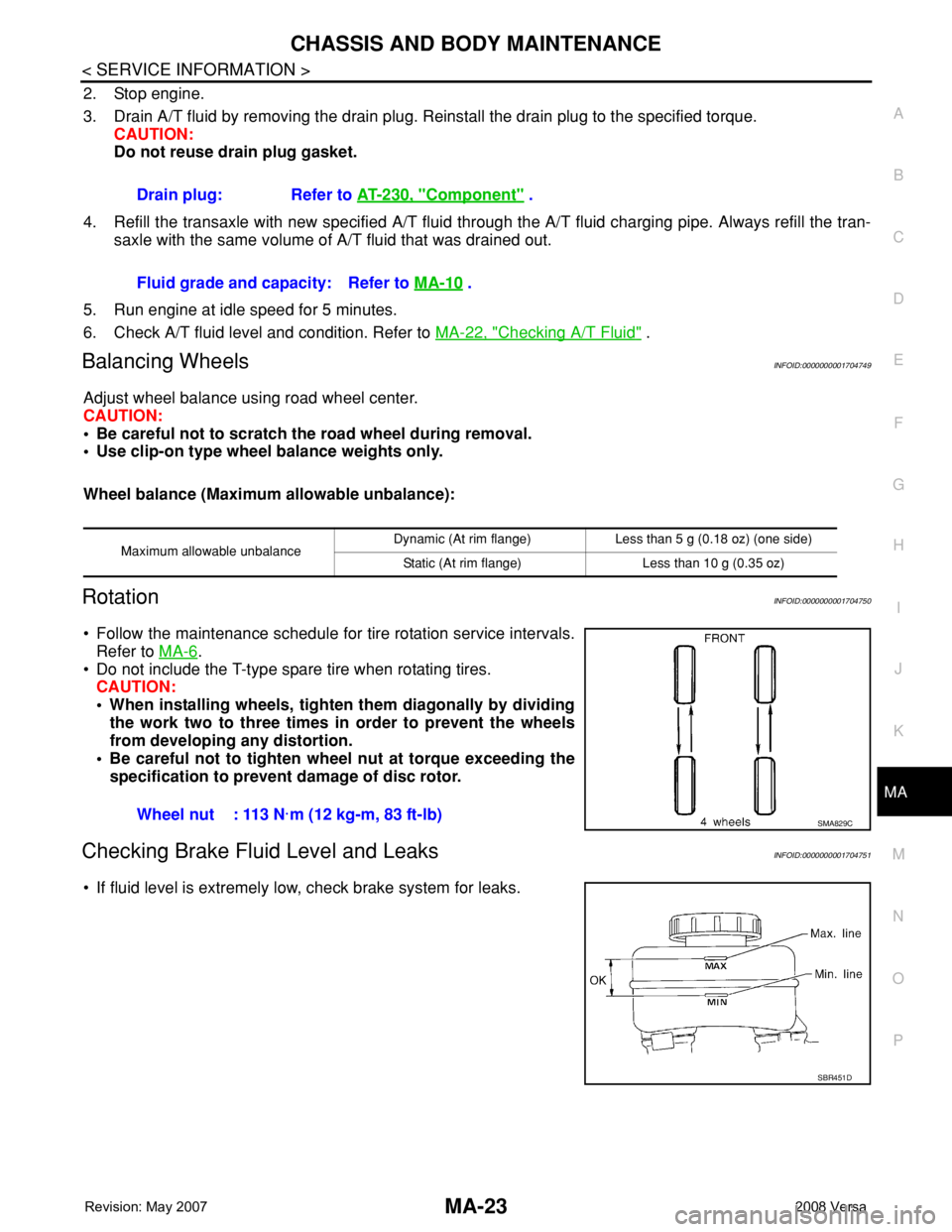
• Follow the maintenance schedule for tire rotation service intervals.
Refer to MA-6
.
• Do not include the T-type spare tire when rotating tires.
CAUTION:
• When installing wheels, tighten them diagonally by dividing
the work two to three times in order to prevent the wheels
from developing any distortion.
• Be careful not to tighten wheel nut at torque exceeding the
specification to prevent damage of disc rotor.
Checking Brake Fluid Level and LeaksINFOID:0000000001704751
• If fluid level is extremely low, check brake system for leaks.Drain plug: Refer to AT-230, "
Component" .
Fluid grade and capacity: Refer to MA-10
.
Maximum allowable unbalanceDynamic (At rim flange) Less than 5 g (0.18 oz) (one side)
Static (At rim flange) Less than 10 g (0.35 oz)
Wheel nut : 113 N·m (12 kg-m, 83 ft-lb)SMA829C
SBR451D
Page 2347 of 2771
PRECAUTIONS
MTC-9
< SERVICE INFORMATION >
C
D
E
F
G
H
I
K
L
MA
B
MTC
N
O
P
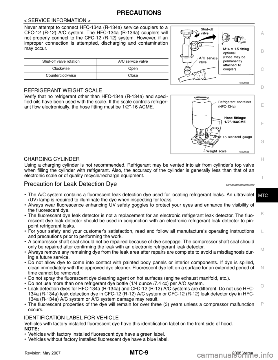
Never attempt to connect HFC-134a (R-134a) service couplers to a
CFC-12 (R-12) A/C system. The HFC-134a (R-134a) couplers will
not properly connect to the CFC-12 (R-12) system. However, if an
improper connection is attempted, discharging and contamination
may occur.
REFRIGERANT WEIGHT SCALE
Verify that no refrigerant other than HFC-134a (R-134a) and speci-
fied oils have been used with the scale. If the scale controls refriger-
ant flow electronically, the hose fitting must be 1/2″-16 ACME.
CHARGING CYLINDER
Using a charging cylinder is not recommended. Refrigerant may be vented into air from cylinder’s top valve
when filling the cylinder with refrigerant. Also, the accuracy of the cylinder is generally less than that of an
electronic scale or of quality recycle/recharge equipment.
Precaution for Leak Detection DyeINFOID:0000000001704282
• The A/C system contains a fluorescent leak detection dye used for locating refrigerant leaks. An ultraviolet
(UV) lamp is required to illuminate the dye when inspecting for leaks.
• Always wear fluorescence enhancing UV safety goggles to protect your eyes and enhance the visibility of
the fluorescent dye.
• The fluorescent dye leak detector is not a replacement for an electronic refrigerant leak detector. The fluo-
rescent dye leak detector should be used in conjunction with an electronic refrigerant leak detector to pin-
point refrigerant leaks.
• For your safety and your customer’s satisfaction, read and follow all manufacture’s operating instructions
and precautions prior to performing the work.
• A compressor shaft seal should not be repaired because of dye seepage. The compressor shaft seal should
only be repaired after confirming the leak with an electronic refrigerant leak detector.
• Always remove any remaining dye from the leak area after repairs are complete to avoid a misdiagnosis dur-
ing a future service.
• Do not allow dye to come into contact with painted body panels or interior components. If dye is spilled,
clean immediately with the approved dye cleaner. Fluorescent dye left on a surface for an extended period of
time cannot be removed.
• Do not spray the fluorescent dye cleaning agent on hot surfaces (engine exhaust manifold, etc.).
• Do not use more than one refrigerant dye bottle (1/4 ounce /7.4 cc) per A/C system.
• Leak detection dyes for HFC-134a (R-134a) and CFC-12 (R-12) A/C systems are different. Do not use HFC-
134a (R-134a) leak detection dye in CFC-12 (R-12) A/C system or CFC-12 (R-12) leak detector dye in HFC-
134a (R-134a) A/C system or A/C system damage may result.
• The fluorescent properties of the dye will remain for over three (3) years unless a compressor malfunction
occurs.
IDENTIFICATION LABEL FOR VEHICLE
Vehicles with factory installed fluorescent dye have this identification label on the front side of hood.
NOTE:
• Vehicles with factory installed fluorescent dye have a green label.
• Vehicles without factory installed fluorescent dye have a blue label.
Shut-off valve rotation A/C service valve
Clockwise Open
Counterclockwise Close
RHA273D
RHA274D
Page 2351 of 2771
PREPARATION
MTC-13
< SERVICE INFORMATION >
C
D
E
F
G
H
I
K
L
MA
B
MTC
N
O
P
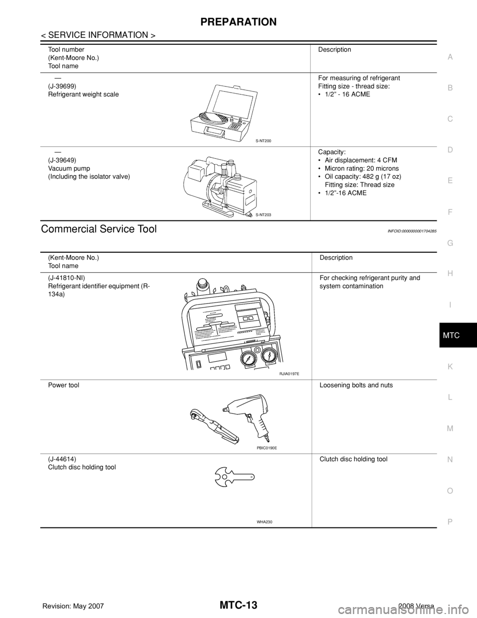
Commercial Service ToolINFOID:0000000001704285
—
(J-39699)
Refrigerant weight scaleFor measuring of refrigerant
Fitting size - thread size:
• 1/2” - 16 ACME
—
(J-39649)
Va c u u m p u m p
(Including the isolator valve)Capacity:
• Air displacement: 4 CFM
• Micron rating: 20 microns
• Oil capacity: 482 g (17 oz)
Fitting size: Thread size
• 1/2”-16 ACME Tool number
(Kent-Moore No.)
Tool nameDescription
S-NT200
S-NT203
(Kent-Moore No.)
Tool nameDescription
(J-41810-NI)
Refrigerant identifier equipment (R-
134a)For checking refrigerant purity and
system contamination
Power toolLoosening bolts and nuts
(J-44614)
Clutch disc holding toolClutch disc holding tool
RJIA0197E
PBIC0190E
WHA230
Page 2412 of 2771
MTC-74
< SERVICE INFORMATION >
REFRIGERANT LINES
REFRIGERANT LINES
HFC-134a (R-134a) Service ProcedureINFOID:0000000001704322
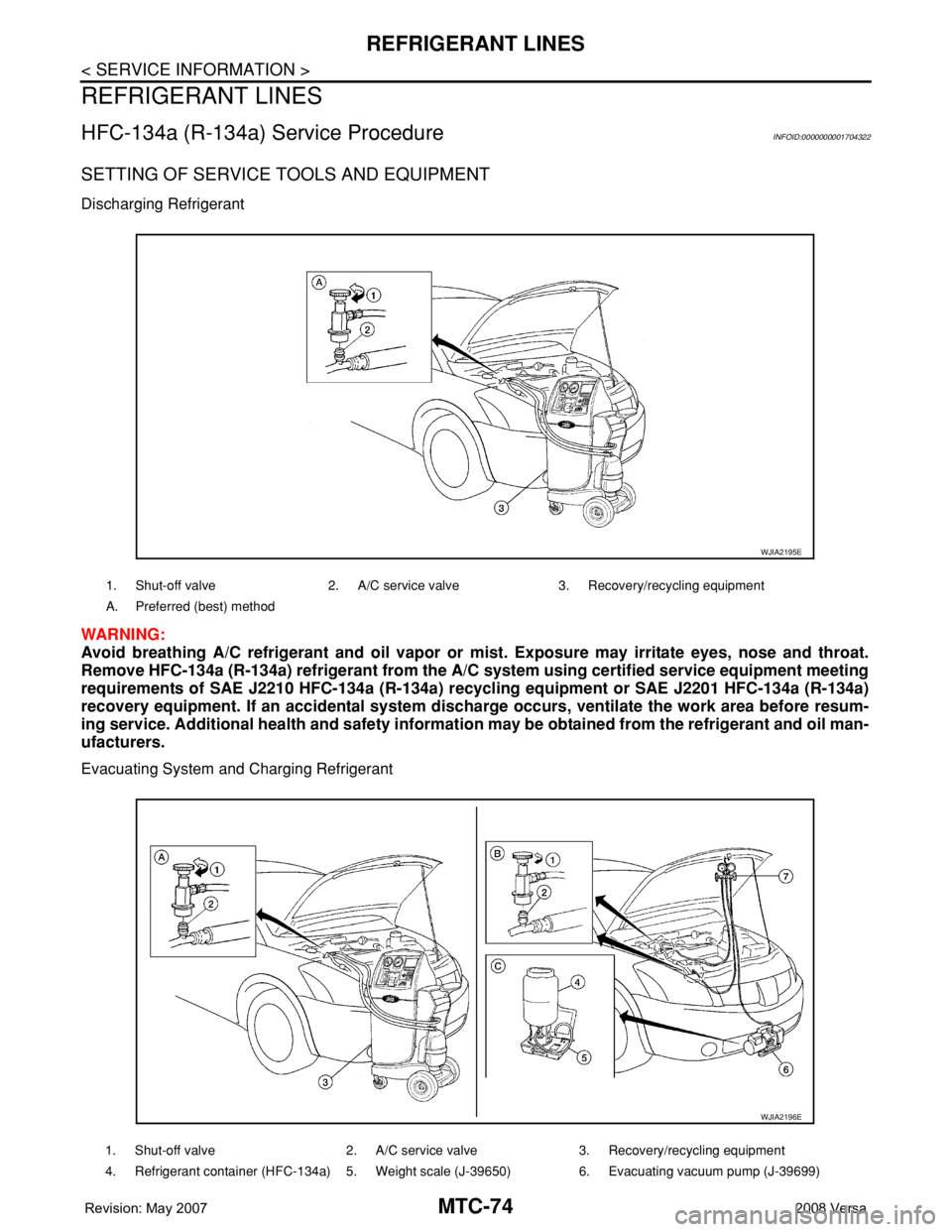
SETTING OF SERVICE TOOLS AND EQUIPMENT
Discharging Refrigerant
WARNING:
Avoid breathing A/C refrigerant and oil vapor or mist. Exposure may irritate eyes, nose and throat.
Remove HFC-134a (R-134a) refrigerant from the A/C system using certified service equipment meeting
requirements of SAE J2210 HFC-134a (R-134a) recycling equipment or SAE J2201 HFC-134a (R-134a)
recovery equipment. If an accidental system discharge occurs, ventilate the work area before resum-
ing service. Additional health and safety information may be obtained from the refrigerant and oil man-
ufacturers.
Evacuating System and Charging Refrigerant
1. Shut-off valve 2. A/C service valve 3. Recovery/recycling equipment
A. Preferred (best) method
WJIA2195E
1. Shut-off valve 2. A/C service valve 3. Recovery/recycling equipment
4. Refrigerant container (HFC-134a) 5. Weight scale (J-39650) 6. Evacuating vacuum pump (J-39699)
WJIA2196E
Page 2686 of 2771
![NISSAN LATIO 2008 Service Repair Manual PRECAUTIONS
STC-3
< SERVICE INFORMATION >[EPS]
C
D
E
F
H
I
J
K
L
MA
B
STC
N
O
P
• Check any possible causes by interviewing the symptom and it’s condition from the customer if any
malfunction, suc NISSAN LATIO 2008 Service Repair Manual PRECAUTIONS
STC-3
< SERVICE INFORMATION >[EPS]
C
D
E
F
H
I
J
K
L
MA
B
STC
N
O
P
• Check any possible causes by interviewing the symptom and it’s condition from the customer if any
malfunction, suc](/manual-img/5/57360/w960_57360-2685.png)
PRECAUTIONS
STC-3
< SERVICE INFORMATION >[EPS]
C
D
E
F
H
I
J
K
L
MA
B
STC
N
O
P
• Check any possible causes by interviewing the symptom and it’s condition from the customer if any
malfunction, such as EPS warning lamp turns ON, occurs.
• Check if air pressure and size of tires are proper, the specified part is used for the steering wheel,
and control unit is genuine part.
• Check if the connection of steering column assembly and steering gear assembly is proper (there is
not looseness of mounting bolts, damage of rods, boots or sealants, and leakage of grease, etc).
• Check if the wheel alignment is adjusted properly.
• Check if there is any damage or modification to suspension or body resulting in increased weight or
altered ground clearance.
• Check if installation conditions of each link and suspension are proper.
• Check if the battery voltage is proper
• Check connection conditions of each connector are proper.
• Before connecting or disconnecting the EPS control unit har-
ness connector, turn ignition switch “OFF” and disconnect
battery ground cable. Because battery voltage is applied to
EPS control unit even if ignition switch is turned “OFF”.
• When connecting or disconnecting pin connectors into or
from EPS control unit, take care not to damage pin terminals
(bend or break).
When connecting pin connectors, make sure that there are no
bends or breaks on EPS control unit pin terminal.
• Before replacing EPS control unit, perform EPS control unit
input/output signal inspection and make sure whether EPS
control unit functions properly or not. Refer to STC-9, "
EPS
Control Unit Input/Output Signal Reference Value".
SEF289H
SEF291H
SDIA1848E
Page 2714 of 2771
WT-6
< SERVICE INFORMATION >
ROAD WHEEL TIRE ASSEMBLY
ROAD WHEEL TIRE ASSEMBLY
Balancing WheelsINFOID:0000000001703749
Adjust wheel balance using road wheel center.
CAUTION:
• Be careful not to scratch the road wheel during removal.
• Use clip-on type wheel balance weights only.
Wheel balance (Maximum allowable unbalance):
RotationINFOID:0000000001703750
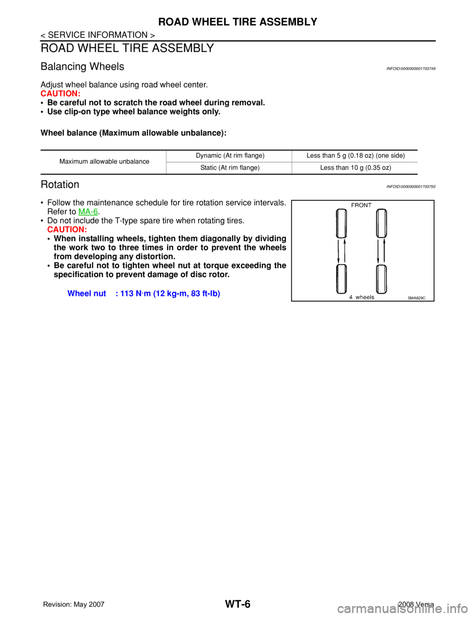
• Follow the maintenance schedule for tire rotation service intervals.
Refer to MA-6
.
• Do not include the T-type spare tire when rotating tires.
CAUTION:
• When installing wheels, tighten them diagonally by dividing
the work two to three times in order to prevent the wheels
from developing any distortion.
• Be careful not to tighten wheel nut at torque exceeding the
specification to prevent damage of disc rotor.
Maximum allowable unbalanceDynamic (At rim flange) Less than 5 g (0.18 oz) (one side)
Static (At rim flange) Less than 10 g (0.35 oz)
Wheel nut : 113 N·m (12 kg-m, 83 ft-lb)SMA829C