Page 500 of 2771
BL-66
< SERVICE INFORMATION >
REMOTE KEYLESS ENTRY SYSTEM
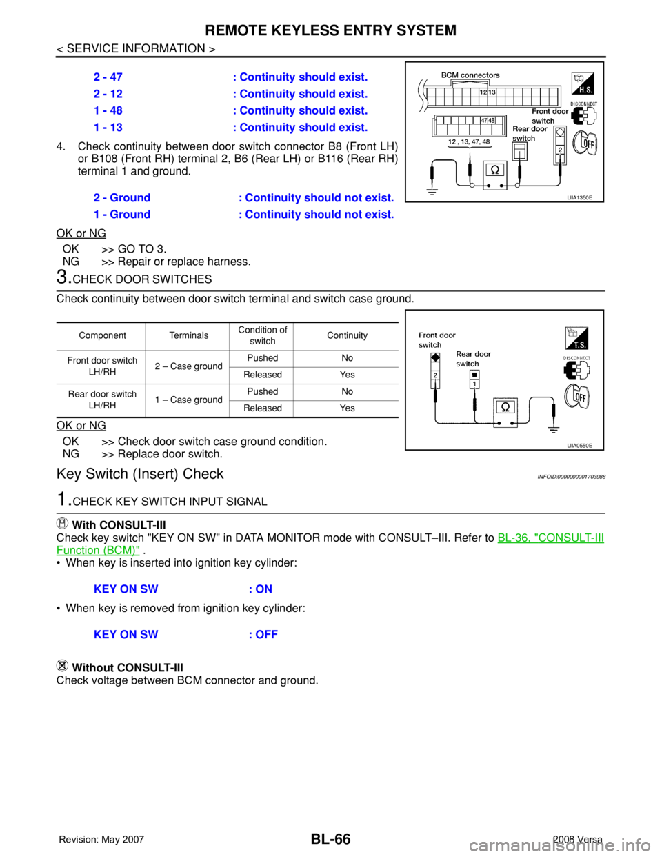
4. Check continuity between door switch connector B8 (Front LH)
or B108 (Front RH) terminal 2, B6 (Rear LH) or B116 (Rear RH)
terminal 1 and ground.
OK or NG
OK >> GO TO 3.
NG >> Repair or replace harness.
3.CHECK DOOR SWITCHES
Check continuity between door switch terminal and switch case ground.
OK or NG
OK >> Check door switch case ground condition.
NG >> Replace door switch.
Key Switch (Insert) CheckINFOID:0000000001703988
1.CHECK KEY SWITCH INPUT SIGNAL
With CONSULT-III
Check key switch "KEY ON SW" in DATA MONITOR mode with CONSULT–III. Refer to BL-36, "
CONSULT-III
Function (BCM)" .
• When key is inserted into ignition key cylinder:
• When key is removed from ignition key cylinder:
Without CONSULT-III
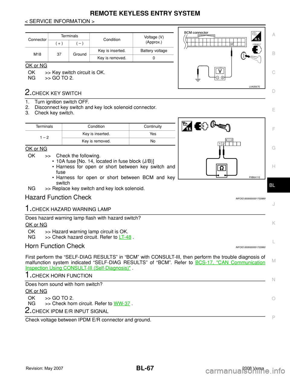
Check voltage between BCM connector and ground.2 - 47 : Continuity should exist.
2 - 12 : Continuity should exist.
1 - 48 : Continuity should exist.
1 - 13 : Continuity should exist.
2 - Ground : Continuity should not exist.
1 - Ground : Continuity should not exist.
LIIA1350E
Component TerminalsCondition of
switchContinuity
Front door switch
LH/RH2 – Case groundPushed No
Released Yes
Rear door switch
LH/RH1 – Case groundPushed No
Released Yes
LIIA0550E
KEY ON SW : ON
KEY ON SW : OFF
Page 501 of 2771
REMOTE KEYLESS ENTRY SYSTEM
BL-67
< SERVICE INFORMATION >
C
D
E
F
G
H
J
K
L
MA
B
BL
N
O
P
OK or NG
OK >> Key switch circuit is OK.
NG >> GO TO 2.
2.CHECK KEY SWITCH
1. Turn ignition switch OFF.
2. Disconnect key switch and key lock solenoid connector.
3. Check key switch.
OK or NG
OK >> Check the following.
• 10A fuse [No. 14, located in fuse block (J/B)]
• Harness for open or short between key switch and
fuse
• Harness for open or short between BCM and key
switch
NG >> Replace key switch and key lock solenoid.
Hazard Function CheckINFOID:0000000001703989
1.CHECK HAZARD WARNING LAMP
Does hazard warning lamp flash with hazard switch?
OK or NG
OK >> Hazard warning lamp circuit is OK.
NG >> Check hazard circuit. Refer to LT- 4 8
.
Horn Function CheckINFOID:0000000001703990
First perform the “SELF-DIAG RESULTS” in “BCM” with CONSULT-III, then perform the trouble diagnosis of
malfunction system indicated “SELF-DIAG RESULTS” of “BCM”. Refer to BCS-17, "
CAN Communication
Inspection Using CONSULT-III (Self-Diagnosis)" .
1.CHECK HORN FUNCTION
Does horn sound with horn switch?
OK or NG
OK >> GO TO 2.
NG >> Check horn circuit. Refer to WW-37
.
2.CHECK IPDM E/R INPUT SIGNAL
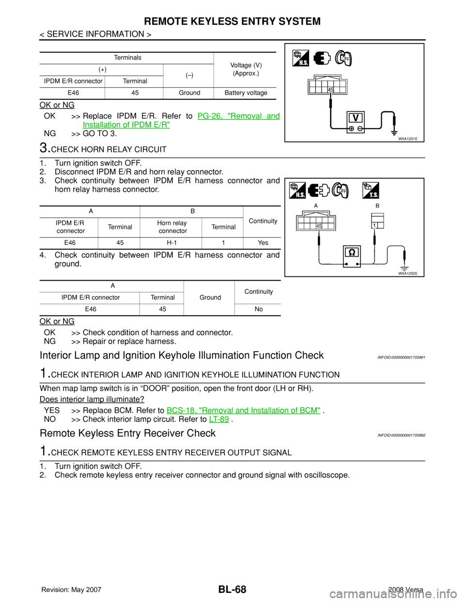
Check voltage between IPDM E/R connector and ground.
ConnectorTe r m i n a l s
ConditionVoltage (V)
(Approx.)
( + ) ( – )
M18 37 GroundKey is inserted. Battery voltage
Key is removed. 0
LIIA0567E
Terminals Condition Continuity
1 – 2Key is inserted. Yes
Key is removed. No
PIIB6411E
Page 502 of 2771
BL-68
< SERVICE INFORMATION >
REMOTE KEYLESS ENTRY SYSTEM
OK or NG
OK >> Replace IPDM E/R. Refer to PG-26, "Removal and
Installation of IPDM E/R"
NG >> GO TO 3.
3.CHECK HORN RELAY CIRCUIT
1. Turn ignition switch OFF.
2. Disconnect IPDM E/R and horn relay connector.
3. Check continuity between IPDM E/R harness connector and
horn relay harness connector.
4. Check continuity between IPDM E/R harness connector and
ground.
OK or NG
OK >> Check condition of harness and connector.
NG >> Repair or replace harness.
Interior Lamp and Ignition Keyhole Illumination Function CheckINFOID:0000000001703991
1.CHECK INTERIOR LAMP AND IGNITION KEYHOLE ILLUMINATION FUNCTION
When map lamp switch is in “DOOR” position, open the front door (LH or RH).
Does interior lamp illuminate?
YES >> Replace BCM. Refer to BCS-18, "Removal and Installation of BCM" .
NO >> Check interior lamp circuit. Refer to LT- 8 9
.
Remote Keyless Entry Receiver CheckINFOID:0000000001703992
1.CHECK REMOTE KEYLESS ENTRY RECEIVER OUTPUT SIGNAL
1. Turn ignition switch OFF.
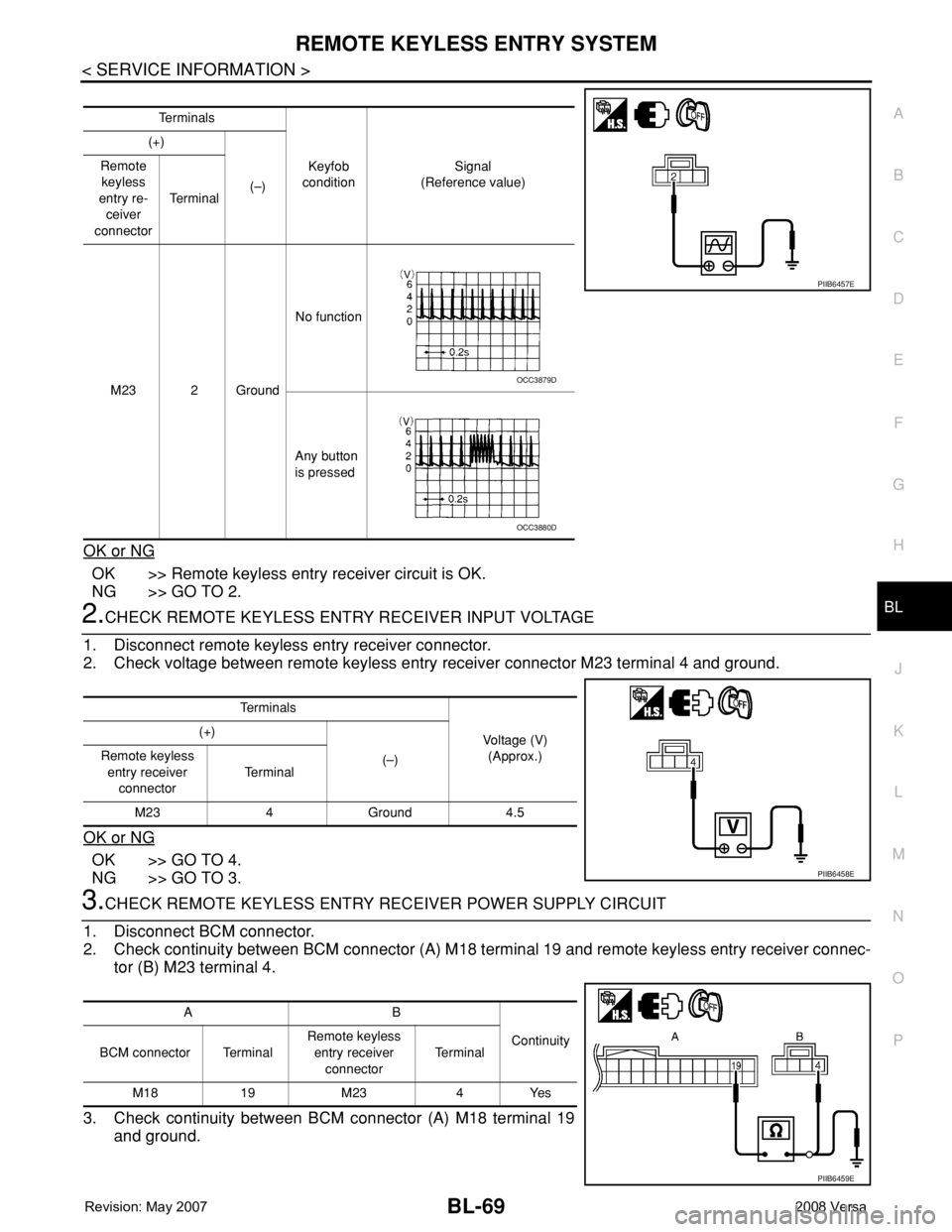
2. Check remote keyless entry receiver connector and ground signal with oscilloscope.
Te r m i n a l s
Voltage (V)
(Approx.) (+)
(–)
IPDM E/R connector Terminal
E46 45 Ground Battery voltage
WIIA1251E
AB
Continuity
IPDM E/R
connectorTe r m i n a lHorn relay
connectorTe r m i n a l
E46 45 H-1 1 Yes
A
GroundContinuity
IPDM E/R connector Terminal
E46 45 No
WIIA1252E
Page 503 of 2771
REMOTE KEYLESS ENTRY SYSTEM
BL-69
< SERVICE INFORMATION >
C
D
E
F
G
H
J
K
L
MA
B
BL
N
O
P
OK or NG
OK >> Remote keyless entry receiver circuit is OK.
NG >> GO TO 2.
2.CHECK REMOTE KEYLESS ENTRY RECEIVER INPUT VOLTAGE
1. Disconnect remote keyless entry receiver connector.
2. Check voltage between remote keyless entry receiver connector M23 terminal 4 and ground.
OK or NG
OK >> GO TO 4.
NG >> GO TO 3.
3.CHECK REMOTE KEYLESS ENTRY RECEIVER POWER SUPPLY CIRCUIT
1. Disconnect BCM connector.
2. Check continuity between BCM connector (A) M18 terminal 19 and remote keyless entry receiver connec-
tor (B) M23 terminal 4.
3. Check continuity between BCM connector (A) M18 terminal 19
and ground.
Te r m i n a l s
Keyfob
conditionSignal
(Reference value) (+)
(–) Remote
keyless
entry re-
ceiver
connectorTe r m i n a l
M23 2 GroundNo function
Any button
is pressed
PIIB6457E
OCC3879D
OCC3880D
Te r m i n a l s
Voltage (V)
(Approx.) (+)
(–) Remote keyless
entry receiver
connectorTe r m i n a l
M23 4 Ground 4.5
PIIB6458E
AB
Continuity
BCM connector TerminalRemote keyless
entry receiver
connectorTe r m i n a l
M18 19 M23 4 Yes
PIIB6459E
Page 504 of 2771
BL-70
< SERVICE INFORMATION >
REMOTE KEYLESS ENTRY SYSTEM
OK or NG
OK >> Replace BCM. Refer to BCS-18, "Removal and Installation of BCM" .
NG >> Repair or replace the harness.
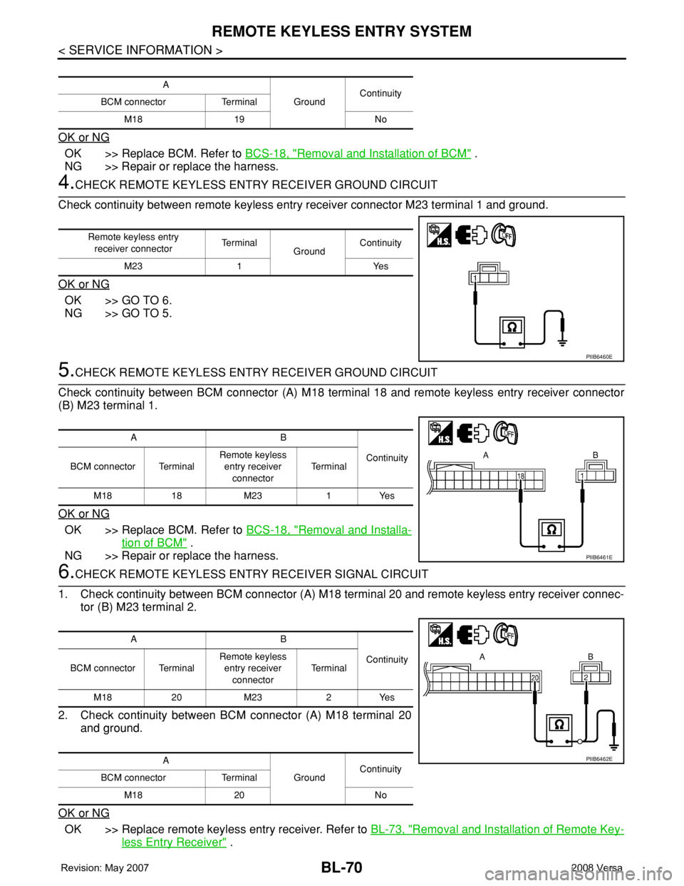
4.CHECK REMOTE KEYLESS ENTRY RECEIVER GROUND CIRCUIT
Check continuity between remote keyless entry receiver connector M23 terminal 1 and ground.
OK or NG
OK >> GO TO 6.
NG >> GO TO 5.
5.CHECK REMOTE KEYLESS ENTRY RECEIVER GROUND CIRCUIT
Check continuity between BCM connector (A) M18 terminal 18 and remote keyless entry receiver connector
(B) M23 terminal 1.
OK or NG
OK >> Replace BCM. Refer to BCS-18, "Removal and Installa-
tion of BCM" .
NG >> Repair or replace the harness.
6.CHECK REMOTE KEYLESS ENTRY RECEIVER SIGNAL CIRCUIT
1. Check continuity between BCM connector (A) M18 terminal 20 and remote keyless entry receiver connec-
tor (B) M23 terminal 2.
2. Check continuity between BCM connector (A) M18 terminal 20
and ground.
OK or NG
OK >> Replace remote keyless entry receiver. Refer to BL-73, "Removal and Installation of Remote Key-
less Entry Receiver" .
A
GroundContinuity
BCM connector Terminal
M18 19 No
Remote keyless entry
receiver connectorTe r m i n a l
GroundContinuity
M23 1 Yes
PIIB6460E
AB
Continuity
BCM connector TerminalRemote keyless
entry receiver
connectorTe r m i n a l
M18 18 M23 1 Yes
PIIB6461E
AB
Continuity
BCM connector TerminalRemote keyless
entry receiver
connectorTe r m i n a l
M18 20 M23 2 Yes
A
GroundContinuity
BCM connector Terminal
M18 20 No
PIIB6462E
Page 505 of 2771

REMOTE KEYLESS ENTRY SYSTEM
BL-71
< SERVICE INFORMATION >
C
D
E
F
G
H
J
K
L
MA
B
BL
N
O
P
NG >> Repair or replace harness.
Keyfob Function (Lock) CheckINFOID:0000000001703993
1.CHECK KEYFOB FUNCTION
With CONSULT-III
Check keyfob function in “DATA MONITOR” mode with CONSULT-III. When pushing lock button of keyfob, the
corresponding monitor item should be turned as follows.
OK or NG
OK >> Keyfob is OK.
NG >> Replace keyfob.
Keyfob Function (Unlock) CheckINFOID:0000000001703994
1.CHECK KEYFOB FUNCTION
With CONSULT-III
Check keyfob function in “DATA MONITOR” mode with CONSULT-III. When pushing unlock button of keyfob,
the corresponding monitor item should be turned as follows.
OK or NG
OK >> Keyfob is OK.
NG >> Replace keyfob.
ID Code Entry ProcedureINFOID:0000000001703995
KEYFOB ID SET UP WITH CONSULT-III
NOTE:
•If a keyfob is lost, the ID code of the lost keyfob must be erased to prevent unauthorized use. A spe-
cific ID code can be erased with CONSULT-III. However, when the ID code of a lost keyfob is not
known, all controller ID codes should be erased. After all ID codes are erased, the ID codes of all
remaining and/or new keyfobs must be re-registered.
•When registering an additional keyfob, the existing ID codes in memory may or may not be erased. If
five ID codes are stored in memory, when an additional code is registered, only the oldest code is
erased. If less than five ID codes are stored in memory, when an additional ID code is registered, the
new ID code is added and no ID codes are erased.
•Entry of maximum five ID codes is allowed. When more than five ID codes are entered, the oldest ID
code will be erased.
•Even if same ID code that is already in the memory is input, the same ID code can be entered. The
code is counted as an additional code.
1. Touch “MULTI REMOTE ENT”.
2. Touch “WORK SUPPORT”.
3. The items are shown on the figure can be set up.
• “REMO CONT ID CONFIR”
Use this mode to confirm if a keyfob ID code is registered or not.
• “REMO CONT ID REGIST”
Use this mode to register a keyfob ID code.
NOTE:
Test item Condition
KEYLESS LOCKPushing LOCK button: ON
Other than above: OFF
Test item Condition
KEYLESS UNLOCKPushing UNLOCK button: ON
Other than above: OFF
Page 506 of 2771
BL-72
< SERVICE INFORMATION >
REMOTE KEYLESS ENTRY SYSTEM
Register the ID code when keyfob or BCM is replaced, or when additional keyfob is required.
• “REMO CONT ID ERASUR”
Use this mode to erase a keyfob ID code.
KEYFOB ID SET UP WITHOUT CONSULT-III
NOTE:
• If a keyfob is lost, the ID code of the lost keyfob must be erased to prevent unauthorized use. A specific ID
code can be erased with CONSULT-III. However, when the ID code of a lost keyfob is not known, all control-
ler ID codes should be erased. After all ID codes are erased, the ID codes of all remaining and/or new key-
fobs must be re-registered.
LIIA1513E
Page 507 of 2771
REMOTE KEYLESS ENTRY SYSTEM
BL-73
< SERVICE INFORMATION >
C
D
E
F
G
H
J
K
L
MA
B
BL
N
O
P
To erase all ID codes in memory, register one ID code (keyfob) five times. After all ID codes are erased, the
ID codes of all remaining and/or new keyfobs must be re-registered.
• When registering an additional keyfob, the existing ID codes in memory may or may not be erased. If five ID
codes are stored in memory, when an additional code is registered, only the oldest code is erased. If less
than five ID codes are stored in memory, when an additional ID code is registered, the new ID code is added
and no ID codes are erased.
• If you need to activate more than two additional new keyfobs, repeat the procedure “Additional ID code
entry” for each new keyfob.
• Entry of maximum five ID codes is allowed. When more than five ID codes are entered, the oldest ID code
will be erased.
• Even if same ID code that is already in the memory is input, the same ID code can be entered. The code is
counted as an additional code.
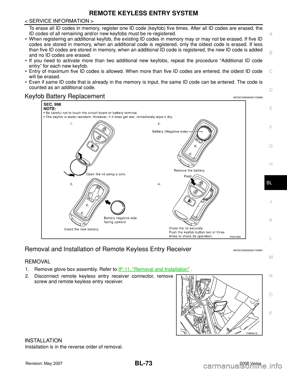
Keyfob Battery ReplacementINFOID:0000000001703996
Removal and Installation of Remote Keyless Entry ReceiverINFOID:0000000001703997
REMOVAL
1. Remove glove box assembly. Refer to IP-11, "Removal and Installation" .
2. Disconnect remote keyless entry receiver connector, remove
screw and remote keyless entry receiver.
INSTALLATION
Installation is in the reverse order of removal.
PIIA4706E
PIIB6541E