2008 NISSAN LATIO check engine light
[x] Cancel search: check engine lightPage 1389 of 2771
DTC P0441 EVAP CONTROL SYSTEM
EC-315
< SERVICE INFORMATION >
C
D
E
F
G
H
I
J
K
L
MA
EC
N
P O
Diagnosis ProcedureINFOID:0000000001702824
1.CHECK EVAP CANISTER
1. Turn ignition switch OFF.
2. Check EVAP canister for cracks.
OK or NG
OK (With CONSULT-II)>>GO TO 2.
OK (Without CONSULT-II)>>GO TO 3.
NG >> Replace EVAP canister.
2.CHECK PURGE FLOW
With CONSULT-II
1. Disconnect vacuum hose connected to EVAP canister purge volume control solenoid valve at EVAP ser-
vice port and install vacuum gauge. For the location of EVAP service port, refer to EC-31, "
Description".
2. Start engine and let it idle.
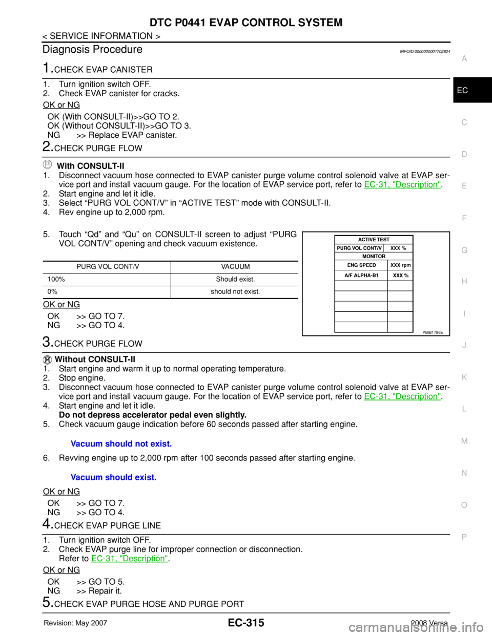
3. Select “PURG VOL CONT/V” in “ACTIVE TEST” mode with CONSULT-II.
4. Rev engine up to 2,000 rpm.
5. Touch “Qd” and “Qu” on CONSULT-II screen to adjust “PURG
VOL CONT/V” opening and check vacuum existence.
OK or NG
OK >> GO TO 7.
NG >> GO TO 4.
3.CHECK PURGE FLOW
Without CONSULT-II
1. Start engine and warm it up to normal operating temperature.
2. Stop engine.
3. Disconnect vacuum hose connected to EVAP canister purge volume control solenoid valve at EVAP ser-
vice port and install vacuum gauge. For the location of EVAP service port, refer to EC-31, "
Description".
4. Start engine and let it idle.
Do not depress accelerator pedal even slightly.
5. Check vacuum gauge indication before 60 seconds passed after starting engine.
6. Revving engine up to 2,000 rpm after 100 seconds passed after starting engine.
OK or NG
OK >> GO TO 7.
NG >> GO TO 4.
4.CHECK EVAP PURGE LINE
1. Turn ignition switch OFF.
2. Check EVAP purge line for improper connection or disconnection.
Refer to EC-31, "
Description".
OK or NG
OK >> GO TO 5.
NG >> Repair it.
5.CHECK EVAP PURGE HOSE AND PURGE PORT
PURG VOL CONT/V VACUUM
100% Should exist.
0% should not exist.
PBIB1786E
Vacuum should not exist.
Vacuum should exist.
Page 1402 of 2771
EC-328
< SERVICE INFORMATION >
DTC P0443 EVAP CANISTER PURGE VOLUME CONTROL SOLENOID VALVE
Do not use ECM ground terminals when measuring input/output voltage. Doing so may result in dam-
age to the ECM's transistor. Use a ground other than ECM terminals, such as the ground.
: Average voltage for pulse signal (Actual pulse signal can be confirmed by oscilloscope.)
Diagnosis ProcedureINFOID:0000000001702833
1.CHECK EVAP CANISTER PURGE VOLUME CONTROL SOLENOID VALVE POWER SUPPLY CIRCUIT
1. Turn ignition switch OFF.
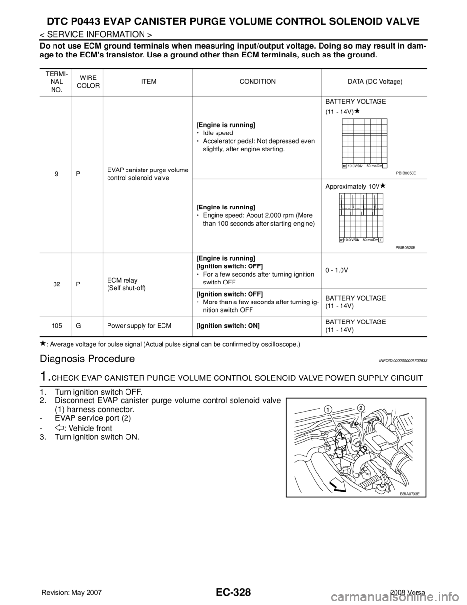
2. Disconnect EVAP canister purge volume control solenoid valve
(1) harness connector.
- EVAP service port (2)
- : Vehicle front
3. Turn ignition switch ON.
TERMI-
NAL
NO.WIRE
COLORITEM CONDITION DATA (DC Voltage)
9PEVAP canister purge volume
control solenoid valve[Engine is running]
• Idle speed
• Accelerator pedal: Not depressed even
slightly, after engine starting.BATTERY VOLTAGE
(11 - 14V)
[Engine is running]
• Engine speed: About 2,000 rpm (More
than 100 seconds after starting engine)Approximately 10V
32 PECM relay
(Self shut-off)[Engine is running]
[Ignition switch: OFF]
• For a few seconds after turning ignition
switch OFF0 - 1.0V
[Ignition switch: OFF]
• More than a few seconds after turning ig-
nition switch OFFBATTERY VOLTAGE
(11 - 14V)
105 G Power supply for ECM[Ignition switch: ON]BATTERY VOLTAGE
(11 - 14V)
PBIB0050E
PBIB0520E
BBIA0703E
Page 1409 of 2771
DTC P0444, P0445 EVAP CANISTER PURGE VOLUME CONTROL SOLENOID
VALVE
EC-335
< SERVICE INFORMATION >
C
D
E
F
G
H
I
J
K
L
MA
EC
N
P O
Do not use ECM ground terminals when measuring input/output voltage. Doing so may result in dam-
age to the ECM's transistor. Use a ground other than ECM terminals, such as the ground.
: Average voltage for pulse signal (Actual pulse signal can be confirmed by oscilloscope.)
Diagnosis ProcedureINFOID:0000000001702841
1.CHECK EVAP CANISTER PURGE VOLUME CONTROL SOLENOID VALVE POWER SUPPLY CIRCUIT
1. Turn ignition switch OFF.
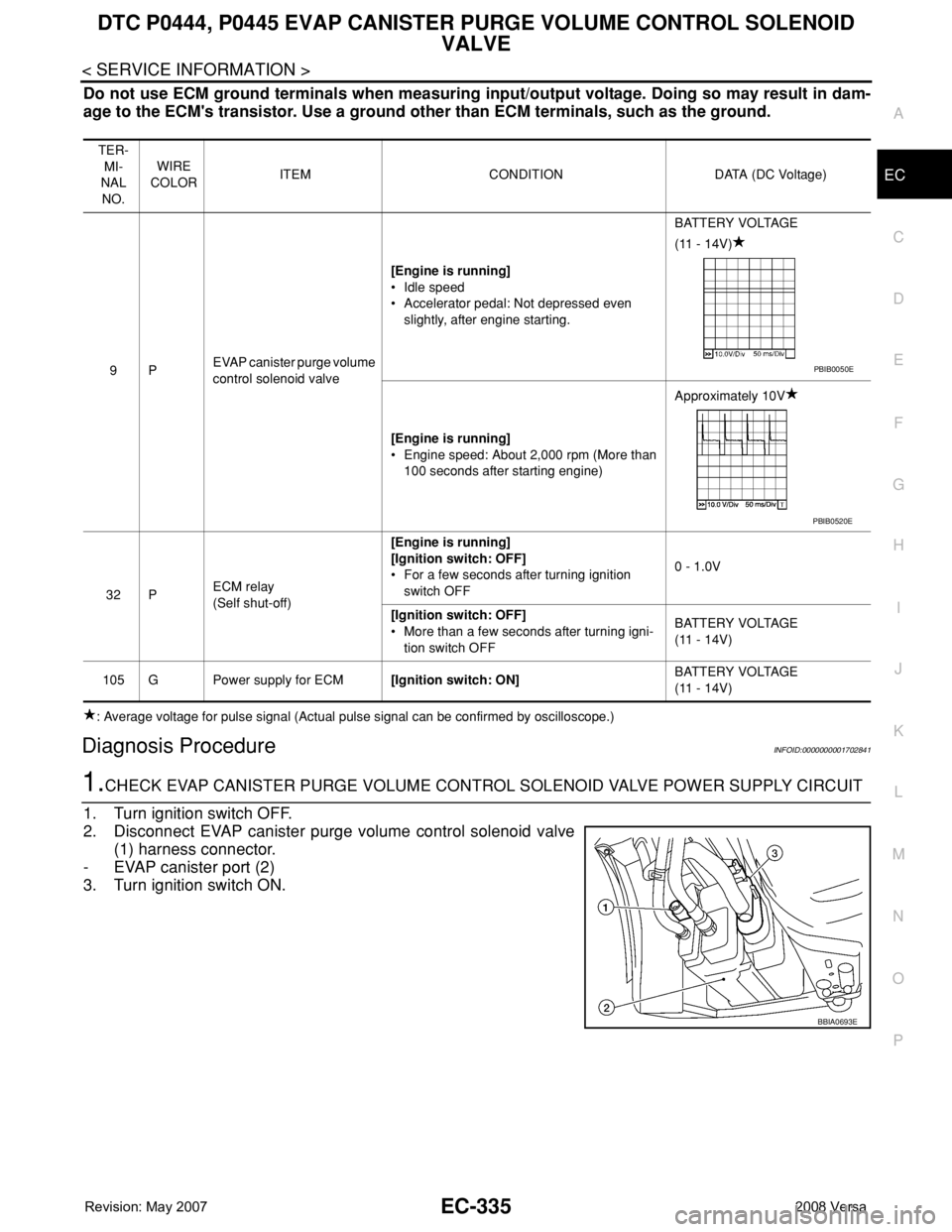
2. Disconnect EVAP canister purge volume control solenoid valve
(1) harness connector.
- EVAP canister port (2)
3. Turn ignition switch ON.
TER-
MI-
NAL
NO.WIRE
COLORITEM CONDITION DATA (DC Voltage)
9PEVAP canister purge volume
control solenoid valve[Engine is running]
• Idle speed
• Accelerator pedal: Not depressed even
slightly, after engine starting.BATTERY VOLTAGE
(11 - 14V)
[Engine is running]
• Engine speed: About 2,000 rpm (More than
100 seconds after starting engine)Approximately 10V
32 PECM relay
(Self shut-off)[Engine is running]
[Ignition switch: OFF]
• For a few seconds after turning ignition
switch OFF0 - 1.0V
[Ignition switch: OFF]
• More than a few seconds after turning igni-
tion switch OFFBATTERY VOLTAGE
(11 - 14V)
105 G Power supply for ECM[Ignition switch: ON]BATTERY VOLTAGE
(11 - 14V)
PBIB0050E
PBIB0520E
BBIA0693E
Page 1426 of 2771
EC-352
< SERVICE INFORMATION >
DTC P0451 EVAP CONTROL SYSTEM PRESSURE SENSOR
2. Turn ignition switch ON and select “DATA MONITOR” mode with
CONSULT-II.
3. Start engine and wait at least 40 seconds.
NOTE:
Do not depress accelerator pedal even slightly.
If 1st trip DTC is detected, go to EC-352, "
Diagnosis Procedure".
WITH GST
Follow the procedure “WITH CONSULT-II” above.
Diagnosis ProcedureINFOID:0000000001702862
1.CHECK GROUND CONNECTIONS
1. Turn ignition switch OFF.
2. Loosen and retighten ground screws on the body.
Refer to EC-142, "
Ground Inspection".
OK or NG
OK >> GO TO 2.
NG >> Repair or replace ground connections.
2.CHECK EVPA CONTROL SYSTEM PRESSURE SENSOR CONNECTOR FOR WATER
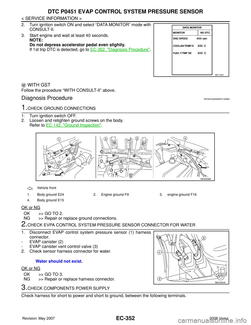
1. Disconnect EVAP control system pressure sensor (1) harness
connector.
- EVAP canister (2)
- EVAP canister vent control valve (3)
2. Check sensor harness connector for water.
OK or NG
OK >> GO TO 3.
NG >> Repair or replace harness connector.
3.CHECK COMPONENTS POWER SUPPLY
Check harness for short to power and short to ground, between the following terminals.
SEF194Y
:Vehicle front
1. Body ground E24 2. Engine ground F9 3. engine ground F16
4. Body ground E15
BBIA0698E
Water should not exist.
BBIA0693E
Page 1523 of 2771
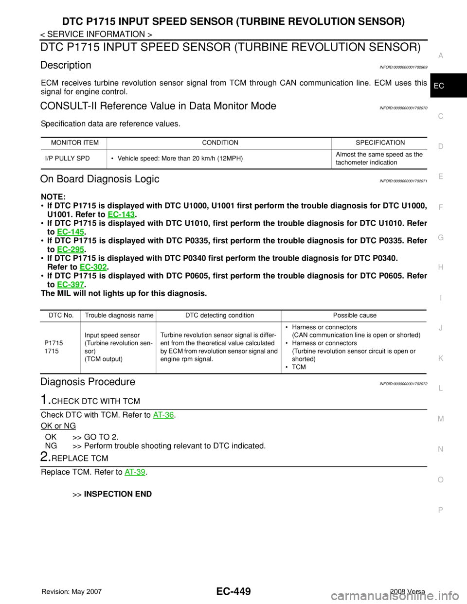
DTC P1715 INPUT SPEED SENSOR (TURBINE REVOLUTION SENSOR)
EC-449
< SERVICE INFORMATION >
C
D
E
F
G
H
I
J
K
L
MA
EC
N
P O
DTC P1715 INPUT SPEED SENSOR (TURBINE REVOLUTION SENSOR)
DescriptionINFOID:0000000001702969
ECM receives turbine revolution sensor signal from TCM through CAN communication line. ECM uses this
signal for engine control.
CONSULT-II Reference Value in Data Monitor ModeINFOID:0000000001702970
Specification data are reference values.
On Board Diagnosis LogicINFOID:0000000001702971
NOTE:
•If DTC P1715 is displayed with DTC U1000, U1001 first perform the trouble diagnosis for DTC U1000,
U1001. Refer to EC-143
.
•If DTC P1715 is displayed with DTC U1010, first perform the trouble diagnosis for DTC U1010. Refer
to EC-145
.
•If DTC P1715 is displayed with DTC P0335, first perform the trouble diagnosis for DTC P0335. Refer
to EC-295
.
•If DTC P1715 is displayed with DTC P0340 first perform the trouble diagnosis for DTC P0340.
Refer to EC-302
.
•If DTC P1715 is displayed with DTC P0605, first perform the trouble diagnosis for DTC P0605. Refer
to EC-397
.
The MIL will not lights up for this diagnosis.
Diagnosis ProcedureINFOID:0000000001702972
1.CHECK DTC WITH TCM
Check DTC with TCM. Refer to AT- 3 6
.
OK or NG
OK >> GO TO 2.
NG >> Perform trouble shooting relevant to DTC indicated.
2.REPLACE TCM
Replace TCM. Refer to AT- 3 9
.
>>INSPECTION END
MONITOR ITEM CONDITION SPECIFICATION
I/P PULLY SPD • Vehicle speed: More than 20 km/h (12MPH)Almost the same speed as the
tachometer indication
DTC No. Trouble diagnosis name DTC detecting condition Possible cause
P1715
1715Input speed sensor
(Turbine revolution sen-
sor)
(TCM output)Turbine revolution sensor signal is differ-
ent from the theoretical value calculated
by ECM from revolution sensor signal and
engine rpm signal.• Harness or connectors
(CAN communication line is open or shorted)
• Harness or connectors
(Turbine revolution sensor circuit is open or
shorted)
•TCM
Page 1629 of 2771

EI-6
< SYMPTOM DIAGNOSIS >
SQUEAK AND RATTLE TROUBLE DIAGNOSIS
If possible, drive the vehicle with the customer until the noise is duplicated. Note any additional information on
the Diagnostic Worksheet regarding the conditions or location of the noise. This information can be used to
duplicate the same conditions when you confirm the repair.
If the noise can be duplicated easily during the test drive, to help identify the source of the noise, try to dupli-
cate the noise with the vehicle stopped by doing one or all of the following:
• Close a door.
• Tap or push/pull around the area where the noise appears to be coming from.
• Rev the engine.
• Use a floor jack to recreate vehicle “twist”.
• At idle, apply engine load (electrical load, half-clutch on M/T model, drive position on A/T model).
• Raise the vehicle on a hoist and hit a tire with a rubber hammer.
• Drive the vehicle and attempt to duplicate the conditions the customer states exist when the noise occurs.
• If it is difficult to duplicate the noise, drive the vehicle slowly on an undulating or rough road to stress the
vehicle body.
CHECK RELATED SERVICE BULLETINS
After verifying the customer concern or symptom, check ASIST for Technical Service Bulletins (TSBs) related
to that concern or symptom.
If a TSB relates to the symptom, follow the procedure to repair the noise.
LOCATE THE NOISE AND IDENTIFY THE ROOT CAUSE
1. Narrow down the noise to a general area. To help pinpoint the source of the noise, use a listening tool
(Chassis Ear: J-39570, Engine Ear: J-39565 and mechanics stethoscope).
2. Narrow down the noise to a more specific area and identify the cause of the noise by:
• Removing the components in the area that you suspect the noise is coming from.
Do not use too much force when removing clips and fasteners, otherwise clips and fasteners
can be broken or lost during the repair, resulting in the creation of new noise.
• Tapping or pushing/pulling the component that you suspect is causing the noise.
Do not tap or push/pull the component with excessive force, otherwise the noise will be elimi-
nated only temporarily.
• Feeling for a vibration with your hand by touching the component(s) that you suspect is (are) causing
the noise.
• Placing a piece of paper between components that you suspect are causing the noise.
• Looking for loose components and contact marks.
Refer to EI-7, "
Generic Squeak and Rattle Troubleshooting".
REPAIR THE CAUSE
• If the cause is a loose component, tighten the component securely.
• If the cause is insufficient clearance between components:
- Separate components by repositioning or loosening and retightening the component, if possible.
- Insulate components with a suitable insulator such as urethane pads, foam blocks, felt cloth tape or ure-
thane tape. A NISSAN Squeak and Rattle Kit (J-43980) is available through your authorized NISSAN Parts
Department.
CAUTION:
Do not use excessive force as many components are constructed of plastic and may be damaged.
Always check with the Parts Department for the latest parts information.
The following materials are contained in the NISSAN Squeak and Rattle Kit (J-43980). Each item can be
ordered separately as needed.
URETHANE PADS [1.5 mm (0.059 in) thick]
Insulates connectors, harness, etc.
76268-9E005: 100 x 135 mm (3.94 x 5.31 in)/76884-71L01: 60 x 85 mm (2.36 x 3.35 in)/76884-71L02: 15 x 25
mm (0.59 x 0.98 in)
INSULATOR (Foam blocks)
Insulates components from contact. Can be used to fill space behind a panel.
73982-9E000: 45 mm (1.77 in) thick, 50 x 50 mm (1.97 x 1.97 in)/73982-50Y00: 10 mm (0.39 in) thick, 50 x 50
mm (1.97 x 1.97 in)
INSULATOR (Light foam block)
80845-71L00: 30 mm (1.18 in) thick, 30 x 50 mm (1.18 x 1.97 in)
FELT CLOTH TAPE
Used to insulate where movement does not occur. Ideal for instrument panel applications.
68370-4B000: 15 x 25 mm (0.59 x 0.98 in) pad/68239-13E00: 5 mm (0.20 in) wide tape roll
Page 1720 of 2771
TIMING CHAIN
EM-43
< SERVICE INFORMATION >
C
D
E
F
G
H
I
J
K
L
MA
EM
N
P O
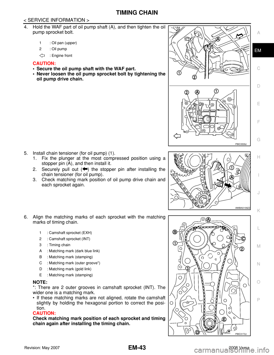
4. Hold the WAF part of oil pump shaft (A), and then tighten the oil
pump sprocket bolt.
CAUTION:
• Secure the oil pump shaft with the WAF part.
• Never loosen the oil pump sprocket bolt by tightening the
oil pump drive chain.
5. Install chain tensioner (for oil pump) (1).
1. Fix the plunger at the most compressed position using a
stopper pin (A), and then install it.
2. Securely pull out ( ) the stopper pin after installing the
chain tensioner (for oil pump).
3. Check matching mark position of oil pump drive chain and
each sprocket again.
6. Align the matching marks of each sprocket with the matching
marks of timing chain.
NOTE:
*: There are 2 outer grooves in camshaft sprocket (INT). The
wider one is a matching mark.
• If these matching marks are not aligned, rotate the camshaft
slightly by holding the hexagonal portion to correct the posi-
tion.
CAUTION:
Check matching mark position of each sprocket and timing
chain again after installing the timing chain.
1 : Oil pan (upper)
2 : Oil pump
: Engine front
PBIC3539J
AWBIA0139ZZ
1 : Camshaft sprocket (EXH)
2 : Camshaft sprocket (INT)
3: Timing chain
A : Matching mark (dark blue link)
B : Matching mark (stamping)
C : Matching mark (outer groove*)
D : Matching mark (gold link)
E : Matching mark (stamping)
PBIC3172J
Page 1752 of 2771
ENGINE ASSEMBLY
EM-75
< SERVICE INFORMATION >
C
D
E
F
G
H
I
J
K
L
MA
EM
N
P O
• When installation directions are specified, install parts according to the directions. Refer to EM-72, "Compo-
nent".
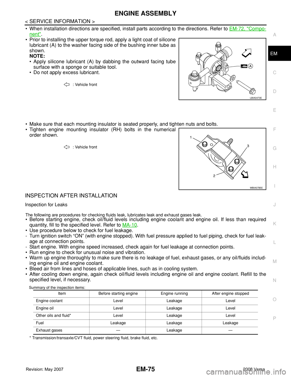
• Prior to installing the upper torque rod, apply a light coat of silicone
lubricant (A) to the washer facing side of the bushing inner tube as
shown.
NOTE:
• Apply silicone lubricant (A) by dabbing the outward facing tube
surface with a sponge or suitable tool.
• Do not apply excess lubricant.
• Make sure that each mounting insulator is seated properly, and tighten nuts and bolts.
• Tighten engine mounting insulator (RH) bolts in the numerical
order shown.
INSPECTION AFTER INSTALLATION
Inspection for Leaks
The following are procedures for checking fluids leak, lubricates leak and exhaust gases leak.
• Before starting engine, check oil/fluid levels including engine coolant and engine oil. If less than required
quantity, fill to the specified level. Refer to MA-10
.
• Use procedure below to check for fuel leakage.
- Turn ignition switch “ON” (with engine stopped). With fuel pressure applied to fuel piping, check for fuel leak-
age at connection points.
- Start engine. With engine speed increased, check again for fuel leakage at connection points.
• Run engine to check for unusual noise and vibration.
• Warm up engine thoroughly to make sure there is no leakage of fuel, exhaust gases, or any oil/fluids includ-
ing engine oil and engine coolant.
• Bleed air from lines and hoses of applicable lines, such as in cooling system.
• After cooling down engine, again check oil/fluid levels including engine oil and engine coolant. Refill to the
specified level, if necessary.
Summary of the inspection items:
* Transmission/transaxle/CVT fluid, power steering fluid, brake fluid, etc.: Vehicle front
LBIA0470E
: Vehicle front
WBIA0785E
Item Before starting engine Engine running After engine stopped
Engine coolant Level Leakage Level
Engine oil Level Leakage Level
Other oils and fluid* Level Leakage Level
Fuel Leakage Leakage Leakage
Exhaust gases — Leakage —