Page 2516 of 2771

PS-10
< SERVICE INFORMATION >
STEERING COLUMN
8. Remove bolt of intermediate shaft (upper side), and then remove intermediate shaft from steering column
assembly.
9. Remove steering column assembly mounting nuts, and then remove steering column assembly from vehi-
cle.
10. Remove bolt of intermediate shaft (lower side), and then remove intermediate shaft from vehicle.
11. Remove screws of bracket and EPS control unit, and then remove bracket and EPS control unit from
steering column assembly.
INSPECTION AFTER REMOVAL
• Check each part of steering column assembly, EPS control unit and intermediate shaft for damage and .
replace as necessary.
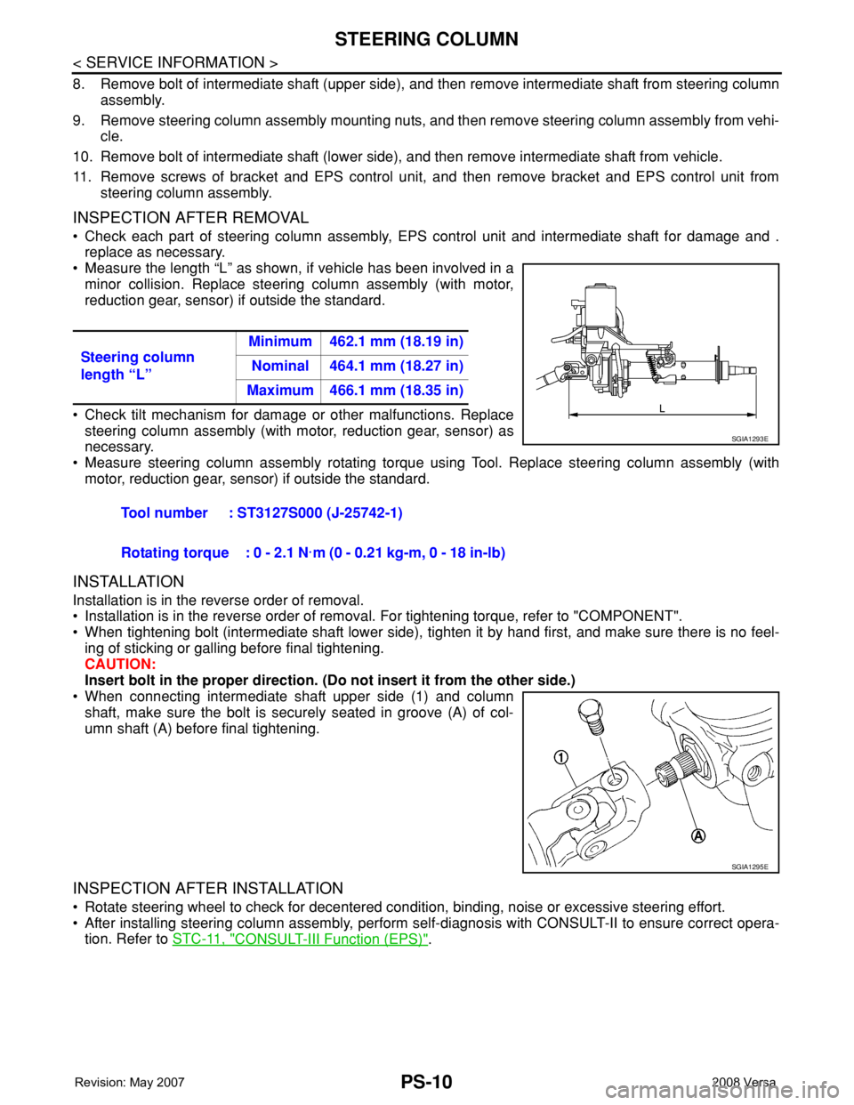
• Measure the length “L” as shown, if vehicle has been involved in a
minor collision. Replace steering column assembly (with motor,
reduction gear, sensor) if outside the standard.
• Check tilt mechanism for damage or other malfunctions. Replace
steering column assembly (with motor, reduction gear, sensor) as
necessary.
• Measure steering column assembly rotating torque using Tool. Replace steering column assembly (with
motor, reduction gear, sensor) if outside the standard.
INSTALLATION
Installation is in the reverse order of removal.
• Installation is in the reverse order of removal. For tightening torque, refer to "COMPONENT".
• When tightening bolt (intermediate shaft lower side), tighten it by hand first, and make sure there is no feel-
ing of sticking or galling before final tightening.
CAUTION:
Insert bolt in the proper direction. (Do not insert it from the other side.)
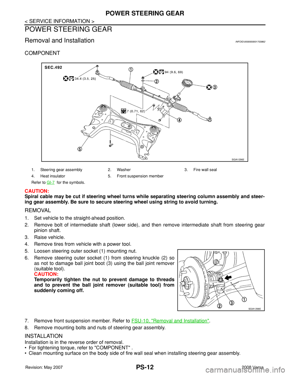
• When connecting intermediate shaft upper side (1) and column
shaft, make sure the bolt is securely seated in groove (A) of col-
umn shaft (A) before final tightening.
INSPECTION AFTER INSTALLATION
• Rotate steering wheel to check for decentered condition, binding, noise or excessive steering effort.
• After installing steering column assembly, perform self-diagnosis with CONSULT-II to ensure correct opera-
tion. Refer to STC-11, "
CONSULT-III Function (EPS)". Steering column
length “L”Minimum 462.1 mm (18.19 in)
Nominal 464.1 mm (18.27 in)
Maximum 466.1 mm (18.35 in)
Tool number : ST3127S000 (J-25742-1)
Rotating torque : 0 - 2.1 N·m (0 - 0.21 kg-m, 0 - 18 in-lb)
SGIA1293E
SGIA1295E
Page 2518 of 2771

PS-12
< SERVICE INFORMATION >
POWER STEERING GEAR
POWER STEERING GEAR
Removal and InstallationINFOID:0000000001703862
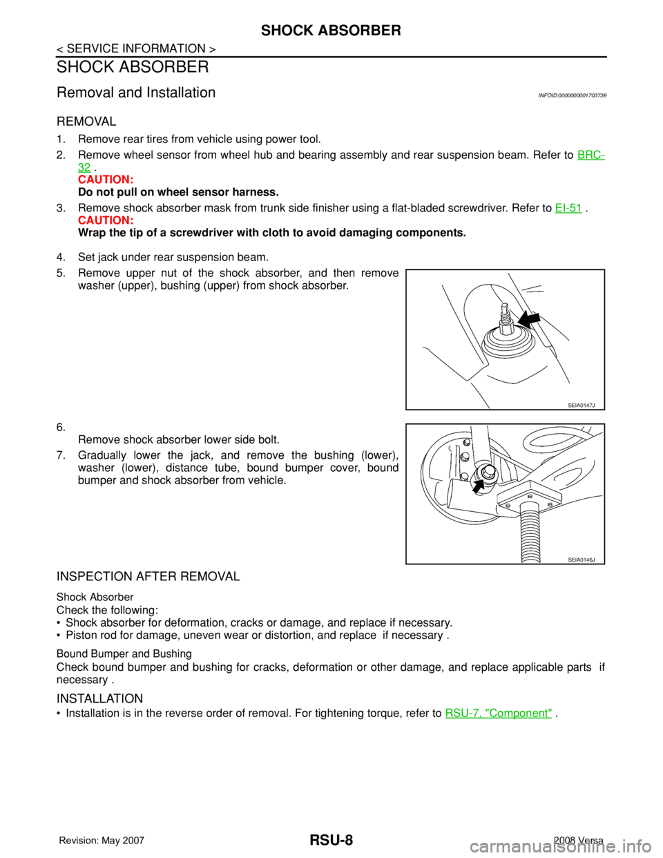
COMPONENT
CAUTION:
Spiral cable may be cut if steering wheel turns while separating steering column assembly and steer-
ing gear assembly. Be sure to secure steering wheel using string to avoid turning.
REMOVAL
1. Set vehicle to the straight-ahead position.
2. Remove bolt of intermediate shaft (lower side), and then remove intermediate shaft from steering gear
pinion shaft.
3. Raise vehicle.
4. Remove tires from vehicle with a power tool.
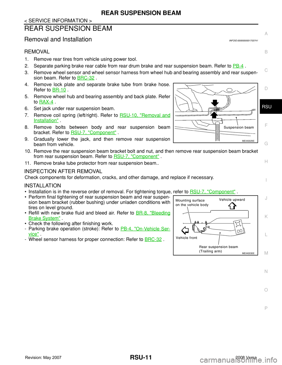
5. Loosen steering outer socket (1) mounting nut.
6. Remove steering outer socket (1) from steering knuckle (2) so
as not to damage ball joint boot (3) using the ball joint remover
(suitable tool).
CAUTION:
Temporarily tighten the nut to prevent damage to threads
and to prevent the ball joint remover (suitable tool) from
suddenly coming off.
7. Remove front suspension member. Refer to FSU-10, "
Removal and Installation".
8. Remove mounting bolts and nuts of steering gear assembly.
INSTALLATION
Installation is in the reverse order of removal.
• For tightening torque, refer to "COMPONENT" .
• Clean mounting surface on the body side of fire wall seal when installing steering gear assembly.
1. Steering gear assembly 2. Washer 3. Fire wall seal
4. Heat insulator 5. Front suspension member
Refer to GI-7
for the symbols.
SGIA1296E
SGIA1298E
Page 2567 of 2771

RSU-8
< SERVICE INFORMATION >
SHOCK ABSORBER
SHOCK ABSORBER
Removal and InstallationINFOID:0000000001703739
REMOVAL
1. Remove rear tires from vehicle using power tool.
2. Remove wheel sensor from wheel hub and bearing assembly and rear suspension beam. Refer to BRC-
32 .
CAUTION:
Do not pull on wheel sensor harness.
3. Remove shock absorber mask from trunk side finisher using a flat-bladed screwdriver. Refer to EI-51
.
CAUTION:
Wrap the tip of a screwdriver with cloth to avoid damaging components.
4. Set jack under rear suspension beam.
5. Remove upper nut of the shock absorber, and then remove
washer (upper), bushing (upper) from shock absorber.
6.
Remove shock absorber lower side bolt.
7. Gradually lower the jack, and remove the bushing (lower),
washer (lower), distance tube, bound bumper cover, bound
bumper and shock absorber from vehicle.
INSPECTION AFTER REMOVAL
Shock Absorber
Check the following:
• Shock absorber for deformation, cracks or damage, and replace if necessary.
• Piston rod for damage, uneven wear or distortion, and replace if necessary .
Bound Bumper and Bushing
Check bound bumper and bushing for cracks, deformation or other damage, and replace applicable parts if
necessary .
INSTALLATION
• Installation is in the reverse order of removal. For tightening torque, refer to RSU-7, "Component" .
SEIA0147J
SEIA0146J
Page 2569 of 2771
RSU-10
< SERVICE INFORMATION >
COIL SPRING
COIL SPRING
Removal and InstallationINFOID:0000000001703740
REMOVAL
1. Remove rear tires from vehicle using power tool.
2. Remove wheel sensor from wheel hub and bearing assembly. Refer to BRC-32
.
CAUTION:
Do not pull on wheel sensor harness.
3. Separate brake tube from wheel cylinder. Refer to BR-10
.
4. Set jack under rear suspension beam.
5. Remove shock absorber lower side bolt. Refer to RSU-8
.
6. Gradually lower the jack, and then remove coil spring and rear
spring rubber seat (upper and lower).
INSPECTION AFTER REMOVAL
Check coil spring and spring rubber seat for deformation, cracks, and damage, and replace it if a malfunction
is detected.
INSTALLATION
• Installation is in the reverse order of removal. For tightening torque, refer to RSU-7, "Component" .
• When installing spring, be sure to securely install the spring end
position aligned to flush of rear spring rubber seat (lower) as
shown.
SEIA0146J
SEIA0149J
Page 2570 of 2771

REAR SUSPENSION BEAM
RSU-11
< SERVICE INFORMATION >
C
D
F
G
H
I
J
K
L
MA
B
RSU
N
O
P
REAR SUSPENSION BEAM
Removal and InstallationINFOID:0000000001703741
REMOVAL
1. Remove rear tires from vehicle using power tool.
2. Separate parking brake rear cable from rear drum brake and rear suspension beam. Refer to PB-4
.
3. Remove wheel sensor and wheel sensor harness from wheel hub and bearing assembly and rear suspen-
sion beam. Refer to BRC-32
.
4. Remove lock plate and separate brake tube from brake hose.
Refer to BR-10
.
5. Remove wheel hub and bearing assembly and back plate. Refer
to RAX-4
.
6. Set jack under rear suspension beam.
7. Remove coil spring (left/right). Refer to RSU-10, "
Removal and
Installation" .
8. Remove bolts between body and rear suspension beam
bracket. Refer to RSU-7, "
Component" .
9. Gradually lower the jack, and then remove rear suspension
beam from vehicle.
10. Remove the rear suspension beam bracket bolt and nut, and then remove rear suspension beam bracket
from rear suspension beam. Refer to RSU-7, "
Component" .
11. Remove brake tube protector from rear suspension beam..
INSPECTION AFTER REMOVAL
Check components for deformation, cracks, and other damage, and replace if necessary.
INSTALLATION
• Installation is in the reverse order of removal. For tightening torque, refer to RSU-7, "Component" .
• Perform final tightening of rear suspension beam and rear suspen-
sion beam bracket (rubber bushing) under unladen conditions with
tires on level ground.
• Refill with new brake fluid and bleed air. Refer to BR-8, "
Bleeding
Brake System" .
• Check the following after finishing work.
- Parking brake operation (stroke): Refer to PB-4, "
On-Vehicle Ser-
vice" .
- Wheel sensor harness for proper connection: Refer to BRC-32
.
MEIA0029E
MEIA0030E
Page:
< prev 1-8 9-16 17-24