2008 NISSAN LATIO mirror
[x] Cancel search: mirrorPage 1965 of 2771
GW-64
< SERVICE INFORMATION >
DOOR MIRROR
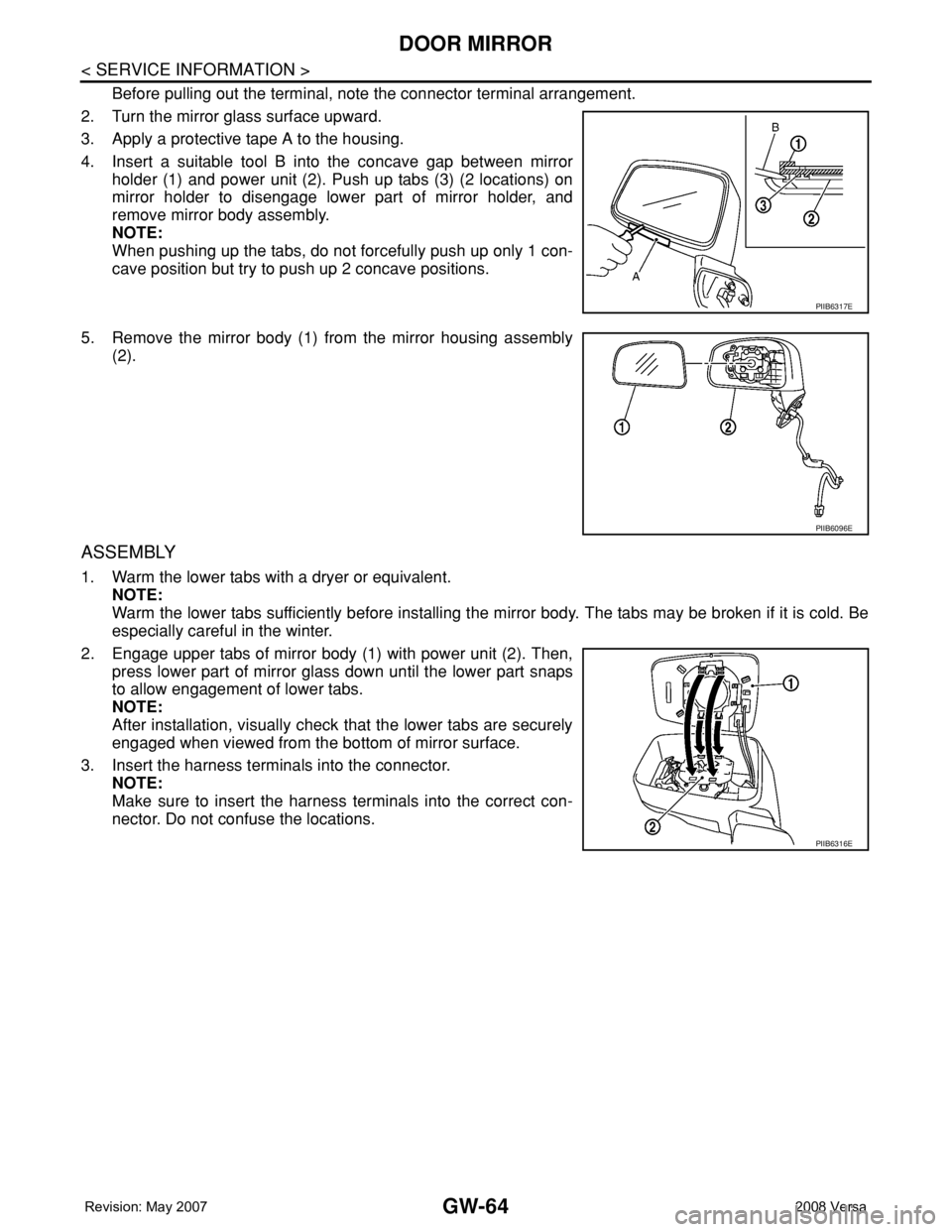
Before pulling out the terminal, note the connector terminal arrangement.
2. Turn the mirror glass surface upward.
3. Apply a protective tape A to the housing.
4. Insert a suitable tool B into the concave gap between mirror
holder (1) and power unit (2). Push up tabs (3) (2 locations) on
mirror holder to disengage lower part of mirror holder, and
remove mirror body assembly.
NOTE:
When pushing up the tabs, do not forcefully push up only 1 con-
cave position but try to push up 2 concave positions.
5. Remove the mirror body (1) from the mirror housing assembly
(2).
ASSEMBLY
1. Warm the lower tabs with a dryer or equivalent.
NOTE:
Warm the lower tabs sufficiently before installing the mirror body. The tabs may be broken if it is cold. Be
especially careful in the winter.
2. Engage upper tabs of mirror body (1) with power unit (2). Then,
press lower part of mirror glass down until the lower part snaps
to allow engagement of lower tabs.
NOTE:
After installation, visually check that the lower tabs are securely
engaged when viewed from the bottom of mirror surface.
3. Insert the harness terminals into the connector.
NOTE:
Make sure to insert the harness terminals into the correct con-
nector. Do not confuse the locations.
PIIB6317E
PIIB6096E
PIIB6316E
Page 1966 of 2771
INSIDE MIRROR
GW-65
< SERVICE INFORMATION >
C
D
E
F
G
H
J
K
L
MA
B
GW
N
O
P
INSIDE MIRROR
Removal and InstallationINFOID:0000000001704184
REMOVAL
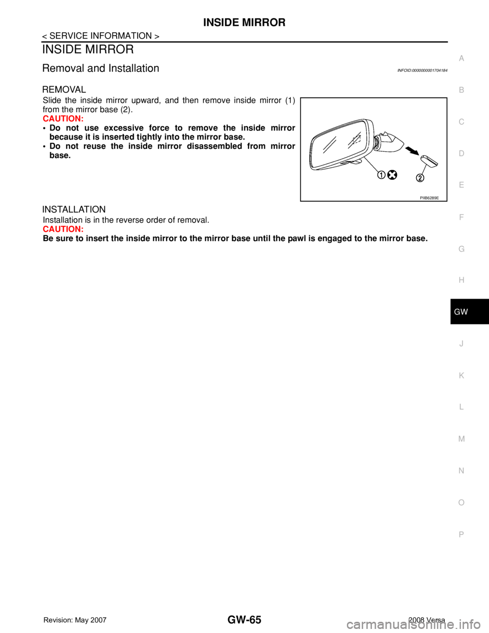
Slide the inside mirror upward, and then remove inside mirror (1)
from the mirror base (2).
CAUTION:
• Do not use excessive force to remove the inside mirror
because it is inserted tightly into the mirror base.
• Do not reuse the inside mirror disassembled from mirror
base.
INSTALLATION
Installation is in the reverse order of removal.
CAUTION:
Be sure to insert the inside mirror to the mirror base until the pawl is engaged to the mirror base.
PIIB6289E
Page 2242 of 2771

ILLUMINATION
LT-105
< SERVICE INFORMATION >
C
D
E
F
G
H
I
J
L
MA
B
LT
N
O
P
ILLUMINATION
System DescriptionINFOID:0000000001704480
The control of the illumination lamps operation is dependent upon the position of the lighting switch. When the
lighting switch is placed in the 1ST or 2ND position, the BCM (body control module) receives input signal
requesting the illumination lamps to illuminate. This input signal is communicated to IPDM E/R (intelligent
power distribution module engine room) across CAN communication lines. CPU (central processing unit)
located in the IPDM E/R controls the tail lamp relay coil. This relay, when energized, directs power to the illu-
mination lamps, which then illuminate.
Power is supplied at all times
• to ignition relay, located in IPDM E/R,
• to tail lamp relay, located in IPDM E/R,
• through 15A fuse (No. 52, located in IPDM E/R) and
• through 20A fuse (No. 53, located in IPDM E/R)
• to CPU located in IPDM E/R,
• through 40A fusible link (letter g , located in fuse and fusible link box)
• to BCM terminal 70, and
• through 10A fuse [No. 8, located in fuse block (J/B)]
• to BCM terminal 57.
With the ignition switch in the ON or START position, power is supplied
• to ignition relay, located in IPDM E/R, and
• through 10A fuse [No. 6, located in fuse block (J/B)]
• to BCM terminal 38.
With the ignition switch in the ACC or ON position, power is supplied
• through 10A fuse [No. 20, located in fuse block (J/B)]
• to BCM terminal 11.
Ground is supplied
• to BCM terminal 67
• through grounds M57 and M61, and
• to IPDM E/R terminals 39 and 59
• through grounds E15 and E24.
ILLUMINATION OPERATION BY LIGHTING SWITCH
With the lighting switch in the 1ST or 2ND position, BCM receives input signal requesting the illumination
lamps to illuminate. This input signal is communicated to IPDM E/R across CAN communication lines. CPU
located in the IPDM E/R controls the tail lamp relay coil, which, when energized, directs power
• through 10A fuse (No. 37, located in IPDM E/R)
• through IPDM E/R terminal 29
• to microphone terminal 3 (with Bluetooth)
• to illumination control switch terminal 1
• to glove box lamp terminal 1 (with glovebox lamp)
• to audio unit terminal 9
• to front air control terminal 5
• to A/T device terminal 3 (with 4-speed A/T)
• to CVT device terminal 3 (with CVT)
• to hazard switch terminal 3
• to combination meter terminal 12
• to door mirror remote control switch terminal 16, and
Ground is supplied
• to microphone terminal 2 (with Bluetooth)
• to glove box lamp terminal 2 (with glove box lamp), and
• to illumination control switch terminal 3
• through grounds M57 and M61.
The illumination control switch controls illumination intensity by varying the ground to the following
• through illumination control switch terminal 2
• to audio unit terminal 8
• to front air control terminal 6
• to A/T device terminal 4 (with 4-speed A/T)
• to CVT device terminal 3 (with CVT)
• to hazard switch terminal 4
Page 2243 of 2771

LT-106
< SERVICE INFORMATION >
ILLUMINATION
• to combination meter terminal 13,
• to door mirror remote control switch terminal 15,
With power and ground supplied, illumination lamps illuminate.
EXTERIOR LAMP BATTERY SAVER CONTROL
Refer to LT-72, "System Description" .
CAN Communication System DescriptionINFOID:0000000001704481
Refer to LAN-6, "System Description" .
Page 2423 of 2771
REFRIGERANT LINES
MTC-85
< SERVICE INFORMATION >
C
D
E
F
G
H
I
K
L
MA
B
MTC
N
O
P
Checking System for Leaks Using the Fluorescent Leak DetectorINFOID:0000000001704334
1. Check A/C system for leaks using the UV lamp and safety goggles J-42220 in a low sunlight area (area
without windows preferable). Illuminate all components, fittings and lines. The dye will appear as a bright
green/yellow area at the point of leakage. Fluorescent dye observed at the evaporator drain opening indi-
cates an evaporator core assembly (tubes, core or expansion valve) leak.
2. If the suspected area is difficult to see, use an adjustable mirror or wipe the area with a clean shop rag or
cloth, with the UV lamp for dye residue.
3. After the leak is repaired, remove any residual dye using dye cleaner J-43872 to prevent future misdiag-
nosis.
4. Perform a system performance check and verify the leak repair with an approved electronic refrigerant
leak detector.
NOTE:
Other gases in the work area or substances on the A/C components, for example, anti-freeze, windshield
washer fluid, solvents and oils, may falsely trigger the leak detector. Make sure the surfaces to be checked are
clean.
Clean with a dry cloth or blow off with shop air.
Do not allow the sensor tip of the detector to contact with any substance. This can also cause false readings
and may damage the detector.
Dye InjectionINFOID:0000000001704335
(This procedure is only necessary when recharging the system or when the compressor has seized and was
replaced.)
1. Check A/C system static (at rest) pressure. Pressure must be at least 345 kPa (3.45 bar, 3.52 kg/cm
2, 50
psi).
2. Pour one bottle (1/4 ounce / 7.4 cc) of the A/C refrigerant dye into the injector tool J-41459.
3. Connect the injector tool to the A/C low-pressure side service fitting.
4. Start engine and switch A/C ON.
5. When the A/C operating (compressor running), inject one bottle (1/4 ounce / 7.4 cc) of fluorescent dye
through the low-pressure service valve using dye injector tool J-41459 (refer to the manufacture’s operat-
ing instructions).
6. With the engine still running, disconnect the injector tool from the service fitting.
CAUTION:
Be careful the A/C system or replacing a component, pour the dye directly into the open system
connection and proceed with the service procedures.
7. Operate the A/C system for a minimum of 20 minutes to mix the dye with the system oil. Depending on the
leak size, operating conditions and location of the leak, it may take from minutes to days for the dye to
penetrate a leak and become visible.
Electronic Refrigerant Leak DetectorINFOID:0000000001704336
PRECAUTIONS FOR HANDLING LEAK DETECTOR
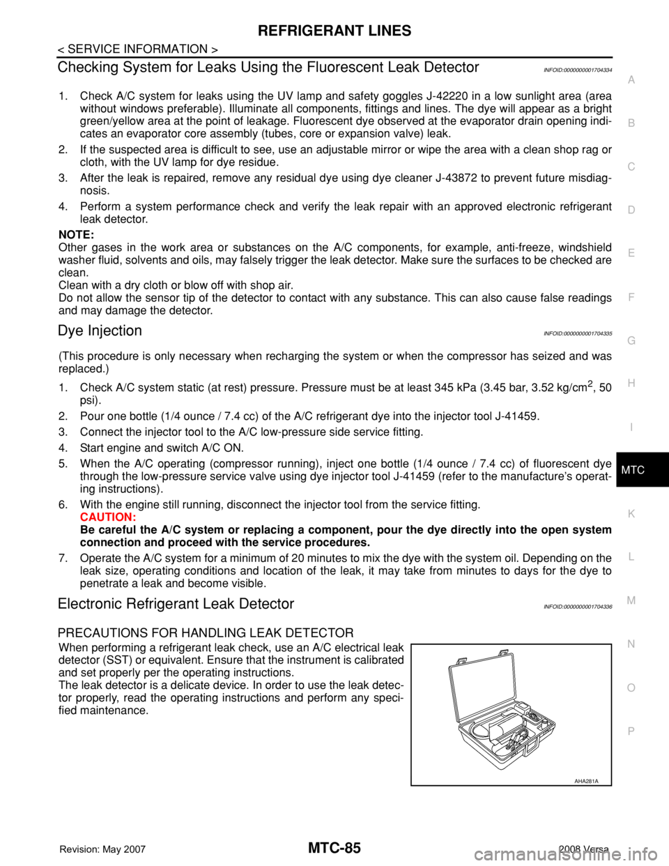
When performing a refrigerant leak check, use an A/C electrical leak
detector (SST) or equivalent. Ensure that the instrument is calibrated
and set properly per the operating instructions.
The leak detector is a delicate device. In order to use the leak detec-
tor properly, read the operating instructions and perform any speci-
fied maintenance.
AHA281A
Page 2471 of 2771
PG-38
< SERVICE INFORMATION >
HARNESS
MAIN HARNESS
AWMIA0122GB
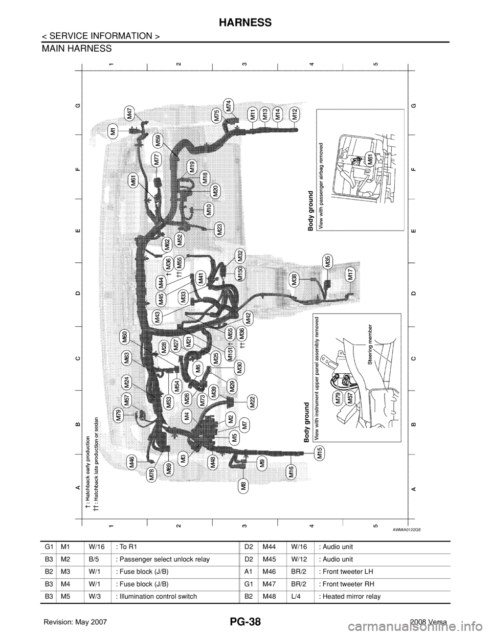
G1 M1 W/16 : To R1 D2 M44 W/16 : Audio unit
B3 M2 B/5 : Passenger select unlock relay D2 M45 W/12 : Audio unit
B2 M3 W/1 : Fuse block (J/B) A1 M46 BR/2 : Front tweeter LH
B3 M4 W/1 : Fuse block (J/B) G1 M47 BR/2 : Front tweeter RH
B3 M5 W/3 : Illumination control switch B2 M48 L/4 : Heated mirror relay
Page 2472 of 2771

HARNESS
PG-39
< SERVICE INFORMATION >
C
D
E
F
G
H
I
J
L
MA
B
PG
N
O
P
C2 M6 W/4 : Steering lock solenoid E2 M52 W/40 : Intelligent key unit
B3 M7 W/16 : Door mirror remote control switch B2 M53 W/16 : EPS control unit
A3 M8 W/16 : To D2 B3 M54 B/2 : EPS control unit
A3 M9 W/16 : To D1 C3 M55† W/4: Hazard switch (hatchback early
production)
E2 M10 GR/2 : Instrument panel antenna D2 M55†† W/4: Hazard switch (hatchback late production
or sedan)
G3 M11 W/4 : To B106 B2 M57 — : Body ground
G4 M12 W/16 : To B101 F2 M59 W/2 : Glove box lamp
G3 M13 W/24 : To B102 C1 M60 L/2 : EPS control unit
G3 M14 W/24 : To B120 F1 M61 — : Body ground
B4 M15 W/16 : To B23 E2 M62 W/2 : Front blower motor
B4 M16 W/24 : To B24 C1 M63 W/4 : Torque sensor
D5 M17 B/1 : Parking brake switch A2 M69 SMJ : To E7
F2 M18 W/40 : BCM (body control module) B2 M73 GR/6: Key switch and ignition knob switch (With
intelligent key)
F2 M19 W/15 : BCM (body control module) G3 M74 W/12 : To D102
F3 M20 B/15 : BCM (body control module) G3 M75 W/12 : To D101
C2 M21 W/4 : NATS antenna amp. F2 M77 Y/4 : Front passenger air bag module
B3 M22 W/16 : Data link connector A2 M78 B/2 : To E11
E3 M23 W/4 : Remote keyless entry receiver B1 M79 — : Body ground
C1 M24 W/40 : Combination meter D3 M150 W/4 : To M32
C3 M25 /2 : Diode-1 C3 M151 W/4 : Front blower motor resistor
B2 M26 W/6 : Ignition switch
C2 M27 GR/6 : Key switch and key lock solenoid
C2 M28 W/16 : Combination switch
C3 M29 Y/6 : Combination switch (spiral cable)
C3 M30 GR/8 : Combination switch (spiral cable)
E3 M32 W/4 : To M150
D2 M33 B/15 : Front air control
D4 M35 Y/28 : Air bag diagnosis sensor unit
D2 M36† W/3: Front passenger air bag OFF indicator
(hatchback early production)
C3 M36†† W/3: Front passenger air bag OFF indicator
(hatchback late production or sedan)
D4 M38 W/6 : A/T device
D4 M38 W/6 : CVT device (without intelligent key)
D4 M38 W/8 : CVT device (with intelligent key)
B3 M39 W/2 : Tire pressure warning check connector
D2 M41 W/2 : Defrost A/C switch
D3 M42 W/3 : Thermo control amp. (without CVT)
D2 M43 W/20 : Audio unit
Page 2486 of 2771
HARNESS
PG-53
< SERVICE INFORMATION >
C
D
E
F
G
H
I
J
L
MA
B
PG
N
O
P
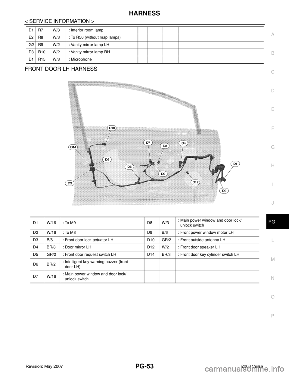
FRONT DOOR LH HARNESS
D1 R7 W/3 : Interior room lamp
E2 R8 W/3 : To R50 (without map lamps)
G2 R9 W/2 : Vanity mirror lamp LH
D3 R10 W/2 : Vanity mirror lamp RH
D1 R15 W/8 : Microphone
D1 W/16 : To M9 D8 W/3: Main power window and door lock/
unlock switch
D2 W/16 : To M8 D9 B/6 : Front power window motor LH
D3 B/6 : Front door lock actuator LH D10 GR/2 : Front outside antenna LH
D4 BR/8 : Door mirror LH D12 W/2 : Front door speaker LH
D5 GR/2 : Front door request switch LH D14 BR/3 : Front door key cylinder switch LH
D6 BR/2: Intelligent key warning buzzer (front
door LH)
D7 W/16: Main power window and door lock/
unlock switch