2008 NISSAN LATIO warning
[x] Cancel search: warningPage 2580 of 2771
SEAT BELTS
SB-9
< ON-VEHICLE REPAIR >
C
D
E
F
G
I
J
K
L
MA
B
SB
N
O
P ALR Function Stationary Check
1. Pull out entire length of seat belt from retractor until a click is heard.
2. Retract the webbing partially. A clicking noise should be heard as the webbing retracts, indicating that the
retractor is in the Automatic Locking Retractors (ALR) mode.
3. Grasp the seat belt and try to pull out the retractor. The webbing must lock and not extend any further. If
NG, replace the retractor assembly.
4. Allow the entire length of the webbing to retract to cancel the automatic locking mode.
ELR Function Moving Check
WARNING:
Perform the following test in a safe, open area clear of other vehicles and obstructions (for example, a
large, empty parking lot). Road surface must be paved and dry. DO NOT perform the following test on
wet or gravel roads or on public streets and highways. This could result in an accident and serious
personal injury. The driver and passenger must be prepared to brace themselves in the event the
retractor does not lock.
1. Fasten driver's seat belt. Buckle a passenger into the seat for the belt that is to be tested.
2. Proceed to the designated safe area.
3. Drive the vehicle at approximately 16 km/h (10 MPH). Notify any passengers of a pending sudden stop
and the driver and passenger must be prepared to brace themselves in the event the retractor does not
lock, apply brakes firmly and make a very hard stop.
During the stop, seat belts should lock and not be extended. If the seat belt retractor assembly does not lock,
perform the retractor off-vehicle check.
SEAT BELT RETRACTOR OFF-VEHICLE CHECK
1. Remove the seat belt retractor. Refer to SB-3.
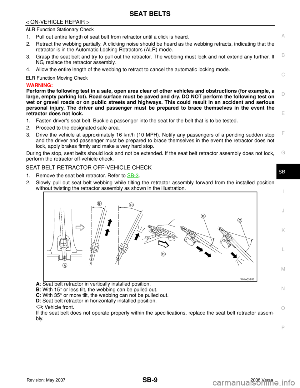
2. Slowly pull out seat belt webbing while tilting the retractor assembly forward from the installed position
without twisting the retractor assembly as shown in the illustration.
A: Seat belt retractor in vertically installed position.
B: With 15° or less tilt, the webbing can be pulled out.
C: With 35° or more tilt, the webbing can not be pulled out.
D: Seat belt retractor in horizontally installed position.
: Vehicle front.
If the seat belt does not operate properly within the specifications, replace the seat belt retractor assem-
bly.
WHIA0351E
Page 2584 of 2771
SC-2
< SERVICE INFORMATION >
PRECAUTIONS
SERVICE INFORMATION
PRECAUTIONS
Precaution for Supplemental Restraint System (SRS) "AIR BAG" and "SEAT BELT
PRE-TENSIONER"
INFOID:0000000001704342
The Supplemental Restraint System such as “AIR BAG” and “SEAT BELT PRE-TENSIONER”, used along
with a front seat belt, helps to reduce the risk or severity of injury to the driver and front passenger for certain
types of collision. This system includes seat belt switch inputs and dual stage front air bag modules. The SRS
system uses the seat belt switches to determine the front air bag deployment, and may only deploy one front
air bag, depending on the severity of a collision and whether the front occupants are belted or unbelted.
Information necessary to service the system safely is included in the SRS and SB section of this Service Man-
ual.
WARNING:
• To avoid rendering the SRS inoperative, which could increase the risk of personal injury or death in
the event of a collision which would result in air bag inflation, all maintenance must be performed by
an authorized NISSAN/INFINITI dealer.
• Improper maintenance, including incorrect removal and installation of the SRS, can lead to personal
injury caused by unintentional activation of the system. For removal of Spiral Cable and Air Bag
Module, see the SRS section.
• Do not use electrical test equipment on any circuit related to the SRS unless instructed to in this
Service Manual. SRS wiring harnesses can be identified by yellow and/or orange harnesses or har-
ness connectors.
Page 2586 of 2771
SC-4
< SERVICE INFORMATION >
BATTERY
BATTERY
How to Handle BatteryINFOID:0000000001704345
CAUTION:
• If it becomes necessary to start the engine with a booster battery and jumper cables, use a 12-volt
booster battery.
• After connecting battery cables, ensure that they are tightly clamped to battery terminals for good
contact.
• Never add distilled water through the hole used to check specific gravity.
METHODS OF PREVENTING OVER-DISCHARGE
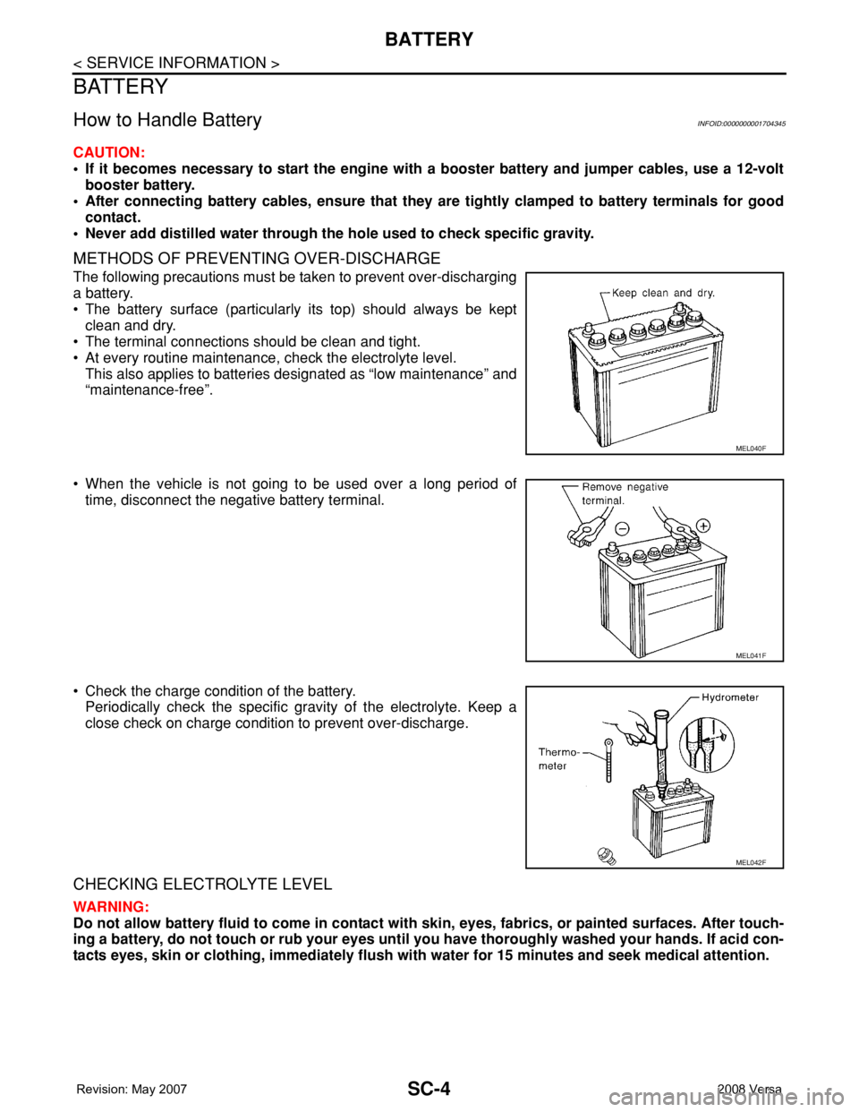
The following precautions must be taken to prevent over-discharging
a battery.
• The battery surface (particularly its top) should always be kept
clean and dry.
• The terminal connections should be clean and tight.
• At every routine maintenance, check the electrolyte level.
This also applies to batteries designated as “low maintenance” and
“maintenance-free”.
• When the vehicle is not going to be used over a long period of
time, disconnect the negative battery terminal.
• Check the charge condition of the battery.
Periodically check the specific gravity of the electrolyte. Keep a
close check on charge condition to prevent over-discharge.
CHECKING ELECTROLYTE LEVEL
WARNING:
Do not allow battery fluid to come in contact with skin, eyes, fabrics, or painted surfaces. After touch-
ing a battery, do not touch or rub your eyes until you have thoroughly washed your hands. If acid con-
tacts eyes, skin or clothing, immediately flush with water for 15 minutes and seek medical attention.
MEL040F
MEL041F
MEL042F
Page 2602 of 2771

SC-20
< SERVICE INFORMATION >
CHARGING SYSTEM
CHARGING SYSTEM
System DescriptionINFOID:0000000001704352
The generator provides DC voltage to operate the vehicle's electrical system and to keep the battery charged.
The voltage output is controlled by the IC regulator.
Power is supplied at all times to generator terminal 3 through
• 10A fuse (No. 29, located in the fuse and fusible link box).
Power is supplied through terminal 1 to charge the battery and operate the vehicle's electrical system. Output
voltage is monitored at terminal 3 by the IC regulator. The charging circuit is protected by the 120A fusible link
[letter a , located in the fusible link box (battery)].
Ground is supplied
• to generator terminal 5
• through body ground F5, and
• through the generator case to the cylinder block
With the ignition switch in the ON or START position, power is supplied
• through 10A fuse [No. 3, located in the fuse block (J/B)]
• to combination meter terminal 28 for the charge warning lamp.
The IC regulator controls ground to terminal 38 of the combination meter through terminal 2 of the generator.
When the ignition is turned on and power becomes available at terminal 2, this "wakes up" the regulator. The
regulator monitors charge output and grounds terminal 2 or leaves it open depending on charge output. With
power and ground supplied, the charge warning lamp will illuminate. When the generator is providing sufficient
voltage, the ground is opened and the charge warning lamp will go off.
If the charge warning lamp illuminates with the engine running, a malfunction is indicated.
Page 2604 of 2771
SC-22
< SERVICE INFORMATION >
CHARGING SYSTEM
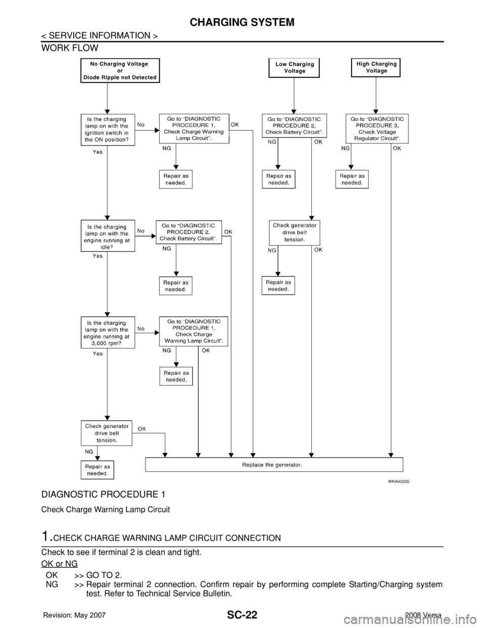
WORK FLOW
DIAGNOSTIC PROCEDURE 1
Check Charge Warning Lamp Circuit
1.CHECK CHARGE WARNING LAMP CIRCUIT CONNECTION
Check to see if terminal 2 is clean and tight.
OK or NG
OK >> GO TO 2.
NG >> Repair terminal 2 connection. Confirm repair by performing complete Starting/Charging system
test. Refer to Technical Service Bulletin.
WKIA4022E
Page 2605 of 2771
CHARGING SYSTEM
SC-23
< SERVICE INFORMATION >
C
D
E
F
G
H
I
J
L
MA
B
SC
N
O
P
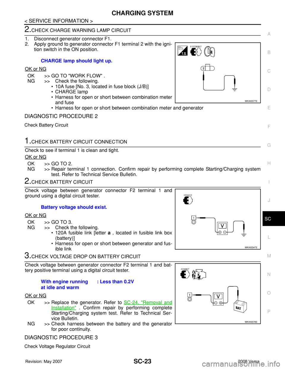
2.CHECK CHARGE WARNING LAMP CIRCUIT
1. Disconnect generator connector F1.
2. Apply ground to generator connector F1 terminal 2 with the igni-
tion switch in the ON position.
OK or NG
OK >> GO TO "WORK FLOW" .
NG >> Check the following.
• 10A fuse [No. 3, located in fuse block (J/B)]
• CHARGE lamp
• Harness for open or short between combination meter
and fuse
• Harness for open or short between combination meter and generator
DIAGNOSTIC PROCEDURE 2
Check Battery Circuit
1.CHECK BATTERY CIRCUIT CONNECTION
Check to see if terminal 1 is clean and tight.
OK or NG
OK >> GO TO 2.
NG >> Repair terminal 1 connection. Confirm repair by performing complete Starting/Charging system
test. Refer to Technical Service Bulletin.
2.CHECK BATTERY CIRCUIT
Check voltage between generator connector F2 terminal 1 and
ground using a digital circuit tester.
OK or NG
OK >> GO TO 3.
NG >> Check the following.
• 120A fusible link [letter a , located in fusible link box
(battery)]
• Harness for open or short between generator and fus-
ible link
3.CHECK VOLTAGE DROP ON BATTERY CIRCUIT
Check voltage between generator connector F2 terminal 1 and bat-
tery positive terminal using a digital circuit tester.
OK or NG
OK >> Replace the generator. Refer to SC-24, "Removal and
Installation" . Confirm repair by performing complete
Starting/Charging system test. Refer to Technical Ser-
vice Bulletin.
NG >> Check harness between the battery and the generator
for poor continuity.
DIAGNOSTIC PROCEDURE 3
Check Voltage Regulator Circuit
CHARGE lamp should light up.
WKIA5577E
Battery voltage should exist.
WKIA5547E
With engine running
at idle and warm: Less than 0.2V
WKIA5578E
Page 2610 of 2771
SE-2
< SERVICE INFORMATION >
PRECAUTIONS
SERVICE INFORMATION
PRECAUTIONS
Precaution for Supplemental Restraint System (SRS) "AIR BAG" and "SEAT BELT
PRE-TENSIONER"
INFOID:0000000001704254
The Supplemental Restraint System such as “AIR BAG” and “SEAT BELT PRE-TENSIONER”, used along
with a front seat belt, helps to reduce the risk or severity of injury to the driver and front passenger for certain
types of collision. Information necessary to service the system safely is included in the SR and SB section of
this Service Manual.
WARNING:
• To avoid rendering the SRS inoperative, which could increase the risk of personal injury or death in
the event of a collision which would result in air bag inflation, all maintenance must be performed by
an authorized NISSAN/INFINITI dealer.
• Improper maintenance, including incorrect removal and installation of the SRS, can lead to personal
injury caused by unintentional activation of the system. For removal of Spiral Cable and Air Bag
Module, see the SR section.
• Do not use electrical test equipment on any circuit related to the SRS unless instructed to in this
Service Manual. SRS wiring harnesses can be identified by yellow and/or orange harnesses or har-
ness connectors.
Service NoticeINFOID:0000000001704255
• When removing or installing various parts, place a cloth or padding onto the vehicle body to prevent
scratches.
• Handle trim, molding instruments, grille, etc. carefully during removing or installing. Be careful not to oil or
damage them.
• Apply sealing compound where necessary when installing parts.
• When applying sealing compound, be careful that the sealing compound does not protrude from parts.
• When replacing any metal parts (for example body outer panel, member, etc.), be sure to take rust preven-
tion measures.
PrecautionINFOID:0000000001704256
• When removing or disassembling any part, be careful not to damage or deform it. Protect parts which may
get in the way with cloth.
• When removing parts with a screwdriver or other tool, protect parts by wrapping tools with vinyl or tape.
• Keep removed parts protected with cloth.
• If a clip is deformed or damaged, replace it.
• If an unreusable part is removed, replace it with a new one.
• Tighten bolts and nuts firmly to the specified torque.
• After re-assembly has been completed, make sure each part functions correctly.
• Remove stains in the following way.
Water-soluble stains:
Dip a soft cloth in warm water, and then squeeze it tightly. After wiping the stain, wipe with a soft dry cloth.
Oil stain:
Dissolve a synthetic detergent in warm water (density of 2 to 3% or less), dip the cloth, then clean off the stain
with the cloth. Next, dip the cloth in fresh water and squeeze it tightly. Then clean off the detergent completely.
Then wipe the area with a soft dry cloth.
• Do not use any organic solvent, such as thinner or benzine.
Page 2635 of 2771

SRS-1
RESTRAINTS
C
D
E
F
G
I
J
K
L
M
SECTION SRS
A
B
SRS
N
O
P
CONTENTS
SUPPLEMENTAL RESTRAINT SYSTEM (SRS)
PRECAUTION ...............................................2
PRECAUTIONS ...................................................2
Precaution for Supplemental Restraint System
(SRS) "AIR BAG" and "SEAT BELT PRE-TEN-
SIONER" ...................................................................
2
Precaution for SRS "AIR BAG" and "SEAT BELT
PRE-TENSIONER" Service ......................................
2
Occupant Classification System Precaution .............2
SYMPTOM DIAGNOSIS ...............................3
SUPPLEMENTAL RESTRAINT SYSTEM
(SRS) ...................................................................
3
SRS Configuration ....................................................3
Driver Air Bag Module ...............................................4
Front Passenger Air Bag Module ..............................4
Front Side Air Bag .....................................................4
Side Curtain Air Bag ..................................................4
Front Seat Belt Pre-tensioner with Load Limiter .......5
Occupant Classification System (OCS) ....................5
Direct-connect SRS Component Connectors ............6
TROUBLE DIAGNOSIS ......................................7
Trouble Diagnosis Introduction .................................7
SRS Component Parts Location ...............................9
Schematic ...............................................................10
Wiring Diagram - SRS- ............................................11
CONSULT-III Function (AIR BAG) ..........................16
Self-Diagnosis Function (Without CONSULT-III) ....17
SRS Operation Check .............................................18
Trouble Diagnosis with CONSULT-III .....................19
Trouble Diagnosis without CONSULT-III ................27
Trouble Diagnosis: "AIR BAG" Warning Lamp
Does Not Turn Off ...................................................
30
Trouble Diagnosis: "AIR BAG" Warning Lamp
Does Not Turn On ...................................................
31
ON-VEHICLE REPAIR .................................33
DRIVER AIR BAG MODULE ............................33
Removal and Installation .........................................33
SPIRAL CABLE ................................................36
Removal and Installation .........................................36
FRONT PASSENGER AIR BAG MODULE ......38
Removal and Installation .........................................38
SIDE CURTAIN AIR BAG MODULE ................39
Component ..............................................................39
Removal and Installation .........................................39
CRASH ZONE SENSOR ...................................41
Removal and Installation .........................................41
SIDE AIR BAG (SATELLITE) SENSOR ...........42
Removal and Installation .........................................42
FRONT SEAT BELT PRE-TENSIONER ...........43
Removal and Installation .........................................43
DIAGNOSIS SENSOR UNIT .............................44
Removal and Installation .........................................44
OCCUPANT CLASSIFICATION SYSTEM
CONTROL UNIT ................................................
45
Removal and Installation .........................................45
COLLISION DIAGNOSIS ..................................46
For Frontal Collision ................................................46
For Side and Rollover Collision ...............................47