2008 NISSAN LATIO light
[x] Cancel search: lightPage 2202 of 2771
COMBINATION SWITCH
LT-65
< SERVICE INFORMATION >
C
D
E
F
G
H
I
J
L
MA
B
LT
N
O
P
OK or NG
OK >> Open circuit in combination switch, GO TO 5.
NG >> Replace BCM. Refer to BCS-18, "
Removal and Installation of BCM" .
5.COMBINATION SWITCH INSPECTION
Referring to table below, perform combination switch inspection.
>> INSPECTION END
Removal and InstallationINFOID:0000000001704437
Refer to LT- 6 0 .
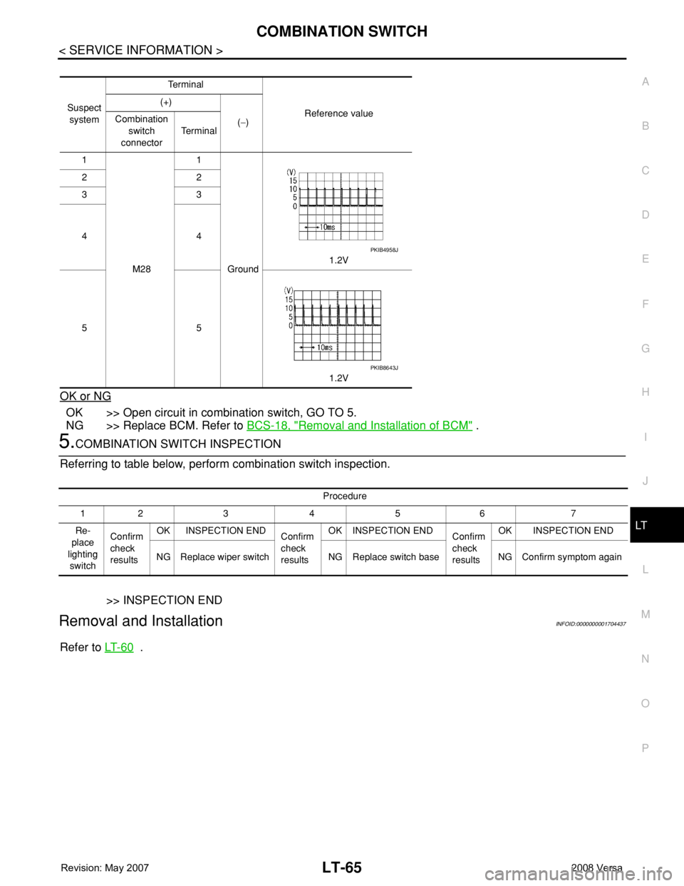
Suspect
systemTe r m i n a l
Reference value (+)
(−) Combination
switch
connectorTe r m i n a l
1
M281
Ground1.2V 22
33
44
55
1.2V
PKIB4958J
PKIB8643J
Procedure
12 3 4 5 6 7
Re-
place
lighting
switchConfirm
check
resultsOK INSPECTION END
Confirm
check
resultsOK INSPECTION END
Confirm
check
resultsOK INSPECTION END
NG Replace wiper switch NG Replace switch base NG Confirm symptom again
Page 2209 of 2771
LT-72
< SERVICE INFORMATION >
PARKING, LICENSE PLATE AND TAIL LAMPS
PARKING, LICENSE PLATE AND TAIL LAMPS
Component Parts and Harness Connector LocationINFOID:0000000001704447
System DescriptionINFOID:0000000001704448
The control of the parking, license plate and tail lamp operation is dependent upon the position of lighting
switch. When the lighting switch is placed in the 1ST position, the BCM (body control module) receives input
signal requesting the parking, license plate and tail lamps to illuminate. This input signal is communicated to
the IPDM E/R (intelligent power distribution module engine room) via the CAN communication lines. The CPU
(central processing unit) located in the IPDM E/R controls the tail lamp relay coil. This relay, when energized,
directs power to parking, license plate and tail lamps, which then illuminate.
Power is supplied at all times
• to ignition relay located in IPDM E/R,
• to tail lamp relay located in IPDM E/R,
• through 15A fuse (No. 52, located in IPDM E/R) and
• through 20A fuse (No. 53, located in IPDM E/R)
• to the CPU located in the IPDM E/R,
• through 40A fusible link (letter g , located in fuse and fusible link block)
• to BCM terminal 70,
• through 10A fuse [No. 8, located in fuse block (J/B)],
• to BCM terminal 57.
With the ignition switch in the ON or START position, power is supplied
• through 10A fuse [No. 6, located in fuse block (J/B)]
• to BCM terminal 38,
• to ignition relay located in IPDM E/R and
• through the ignition relay
• to the CPU of the IPDM E/R.
With the ignition switch in the ACC or ON position, power is supplied
• through 10A fuse [No. 20, located in fuse block (J/B)]
• to BCM terminal 11.
Ground is supplied
• to BCM terminal 67
• through grounds M20 and M61,
• to IPDM E/R terminals 59 and 39
• through grounds E15 and E24.
OPERATION BY LIGHTING SWITCH
With the lighting switch in the 1ST or 2ND position, the BCM receives an input signal requesting parking,
license plate and tail lamps to illuminate. This input signal is communicated to the IPDM E/R via the CAN com-
munication lines. The CPU, located in the IPDM E/R, controls the tail lamp relay coil. When energized, the tail
lamp relay directs power
• through 10A fuse (No. 37, located in IPDM E/R),
• through IPDM E/R terminal 26
• to front combination lamp LH terminal 6, and
• through IPDM E/R terminal 27
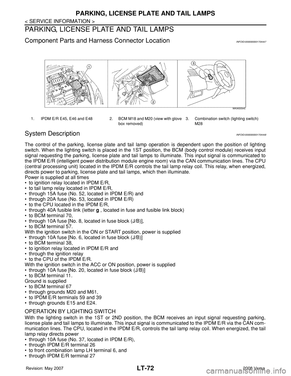
1. IPDM E/R E45, E46 and E48 2. BCM M18 and M20 (view with glove
box removed)3. Combination switch (lighting switch)
M28
WKIA5554E
Page 2210 of 2771
PARKING, LICENSE PLATE AND TAIL LAMPS
LT-73
< SERVICE INFORMATION >
C
D
E
F
G
H
I
J
L
MA
B
LT
N
O
P
• to front combination lamp RH terminal 6,
• through IPDM E/R terminal 28
• to rear combination lamp LH terminal 4 and
• to license plate lamp LH and RH terminal 1,
• through IPDM E/R terminal 29
• to rear combination lamp RH terminal 4.
Ground is supplied
• to front combination lamp LH and RH terminal 7
• through grounds E15 and E24,
• to rear combination lamp LH terminal 1 and
• to license plate lamp LH and RH terminal 2
• through grounds B7 and B19, and
• to rear combination lamp RH terminal 1
• through grounds B117, B132 (all models) and D402 (with hatchback).
With power and ground supplied, parking, license plate and tail lamps illuminate.
COMBINATION SWITCH READING FUNCTION
Refer to BCS-3, "System Description" .
EXTERIOR LAMP BATTERY SAVER CONTROL
When the combination switch (lighting switch) is in the 1ST (or 2ND) position and the ignition switch is turned
from ON or ACC to OFF, the battery saver control feature is activated.
Under this condition, the parking, license and tail lamps remain illuminated for 5 minutes, then the parking,
license plate and tail lamps are turned off.
Exterior lamp battery saver control mode can be changed by the function setting of CONSULT-III.
CAN Communication System DescriptionINFOID:0000000001704449
Refer to LAN-6, "System Description" .
Page 2216 of 2771
PARKING, LICENSE PLATE AND TAIL LAMPS
LT-79
< SERVICE INFORMATION >
C
D
E
F
G
H
I
J
L
MA
B
LT
N
O
P
How to Proceed with Trouble DiagnosisINFOID:0000000001704454
1. Confirm the symptom or customer complaint.
2. Understand operation description and function description. Refer to LT-72, "
System Description" .
3. Perform the preliminary check. Refer to LT-79, "
Preliminary Check" .
4. Check symptom and repair or replace the cause of the malfunction.
5. Do the parking, license plate and tail lamps operate normally? If YES, GO TO 6. If NO, GO TO 4.
6. Inspection End.
Preliminary CheckINFOID:0000000001704455
CHECK POWER SUPPLY AND GROUND CIRCUIT FOR BCM
Refer to BCS-15, "BCM Power Supply and Ground Circuit Inspection" .
CHECK POWER SUPPLY AND GROUND CIRCUIT FOR IPDM E/R
Refer to PG-25, "IPDM E/R Power/Ground Circuit Inspection" .
CONSULT-III Function (BCM)INFOID:0000000001704456
Refer to LT- 11 , "CONSULT-III Function (BCM)" .
CONSULT-III Function (IPDM E/R)INFOID:0000000001704457
Refer to LT-12, "CONSULT-III Function (IPDM E/R)" .
Parking, License Plate and Tail Lamps Do Not IlluminateINFOID:0000000001704458
1.CHECK TAIL LAMP FUSE
Inspect tail lamp 10A fuse (No. 37, located in IPDM E/R).
OK or NG
OK >> GO TO 2.
NG >> Repair harness.
2.CHECK COMBINATION SWITCH INPUT SIGNAL
With CONSULT-III
1. Select “BCM” on CONSULT-III. Select “HEAD LAMP” on “SELECT TEST ITEM” screen.
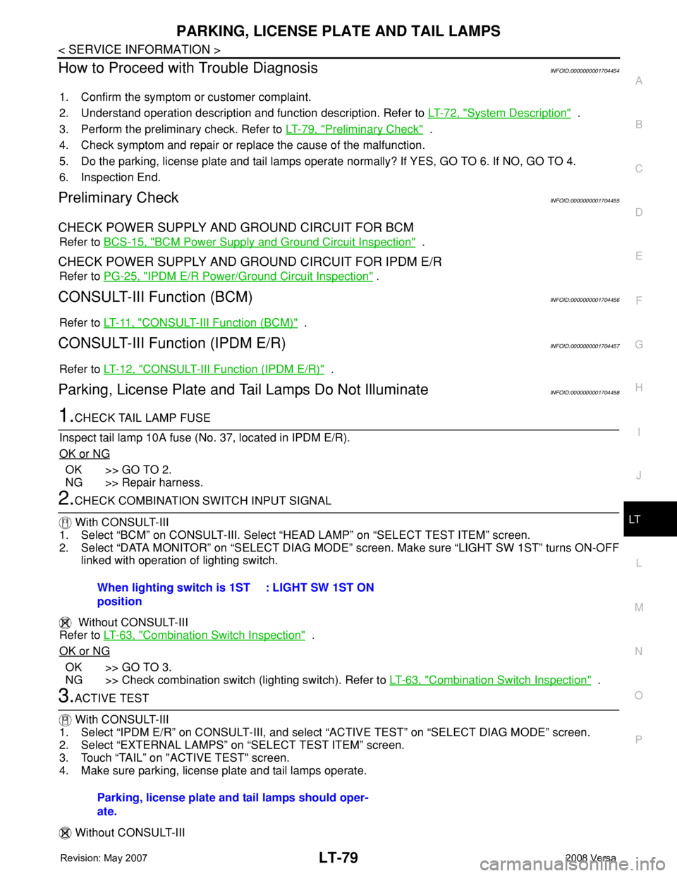
2. Select “DATA MONITOR” on “SELECT DIAG MODE” screen. Make sure “LIGHT SW 1ST” turns ON-OFF
linked with operation of lighting switch.
Without CONSULT-III
Refer to LT-63, "
Combination Switch Inspection" .
OK or NG
OK >> GO TO 3.
NG >> Check combination switch (lighting switch). Refer to LT-63, "
Combination Switch Inspection" .
3.ACTIVE TEST
With CONSULT-III
1. Select “IPDM E/R” on CONSULT-III, and select “ACTIVE TEST” on “SELECT DIAG MODE” screen.
2. Select “EXTERNAL LAMPS” on “SELECT TEST ITEM” screen.
3. Touch “TAIL” on "ACTIVE TEST" screen.
4. Make sure parking, license plate and tail lamps operate.
Without CONSULT-IIIWhen lighting switch is 1ST
position: LIGHT SW 1ST ON
Parking, license plate and tail lamps should oper-
ate.
Page 2217 of 2771
LT-80
< SERVICE INFORMATION >
PARKING, LICENSE PLATE AND TAIL LAMPS
1. Start auto active test. Refer to PG-19, "Auto Active Test" .
2. Make sure parking, license plate and tail lamps operate.
OK or NG
OK >> GO TO 4.
NG >> GO TO 5.
4.CHECK IPDM E/R
1. Select “IPDM E/R” on CONSULT-III, and select “DATA MONITOR” on “SELECT DIAG MODE” screen.
2. Make sure “TAIL&CLR REQ” turns ON when lighting switch is in 1ST position.
OK or NG
OK >> Replace IPDM E/R. Refer to PG-26, "Removal and Installation of IPDM E/R" .
NG >> Replace BCM. Refer to BCS-18, "
Removal and Installation of BCM" .
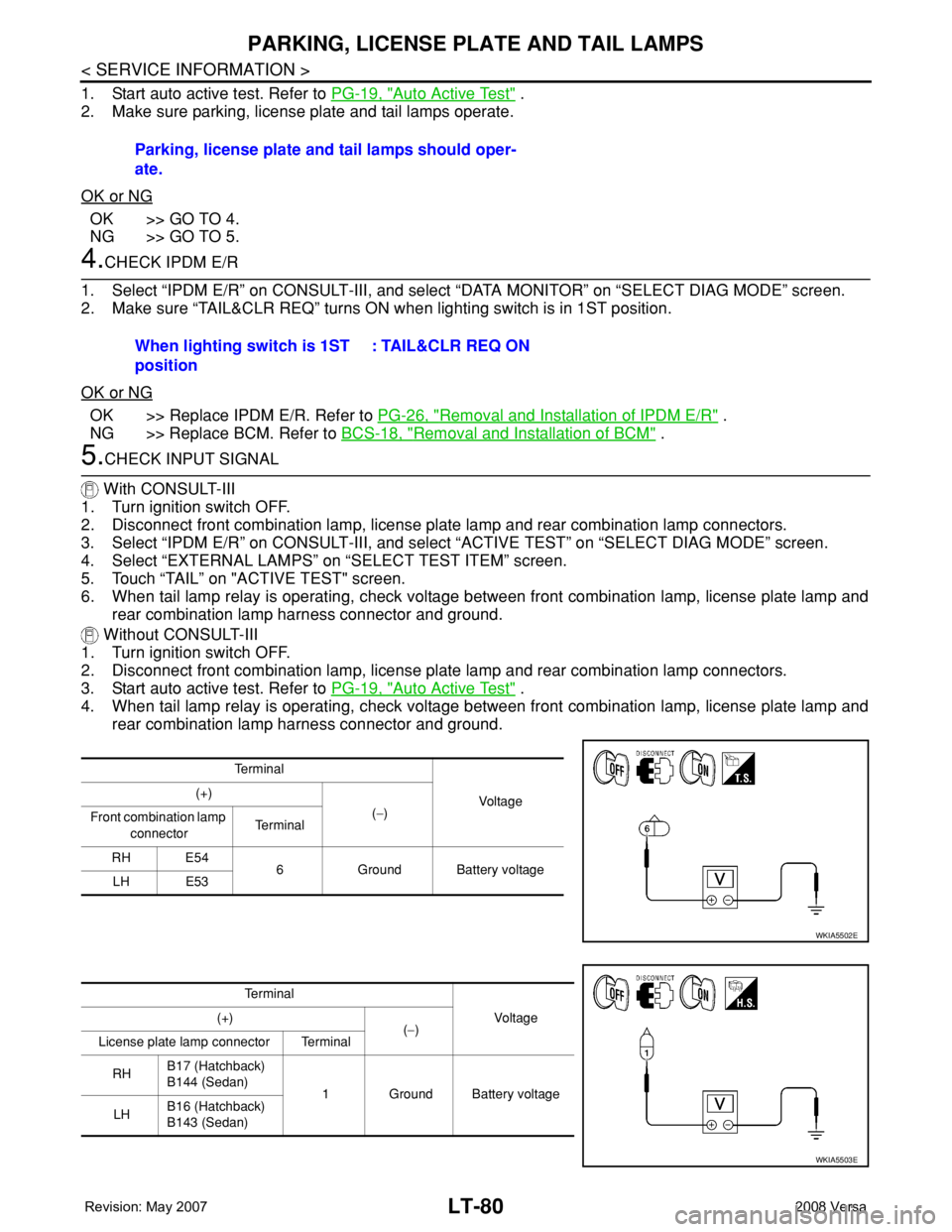
5.CHECK INPUT SIGNAL
With CONSULT-III
1. Turn ignition switch OFF.
2. Disconnect front combination lamp, license plate lamp and rear combination lamp connectors.
3. Select “IPDM E/R” on CONSULT-III, and select “ACTIVE TEST” on “SELECT DIAG MODE” screen.
4. Select “EXTERNAL LAMPS” on “SELECT TEST ITEM” screen.
5. Touch “TAIL” on "ACTIVE TEST" screen.
6. When tail lamp relay is operating, check voltage between front combination lamp, license plate lamp and
rear combination lamp harness connector and ground.
Without CONSULT-III
1. Turn ignition switch OFF.
2. Disconnect front combination lamp, license plate lamp and rear combination lamp connectors.
3. Start auto active test. Refer to PG-19, "
Auto Active Test" .
4. When tail lamp relay is operating, check voltage between front combination lamp, license plate lamp and
rear combination lamp harness connector and ground.Parking, license plate and tail lamps should oper-
ate.
When lighting switch is 1ST
position: TAIL&CLR REQ ON
Te r m i n a l
Voltag e (+)
(−)
Front combination lamp
connectorTe r m i n a l
RH E54
6 Ground Battery voltage
LH E53
WKIA5502E
Te r m i n a l
Vo l ta g e (+)
(−)
License plate lamp connector Terminal
RHB17 (Hatchback)
B144 (Sedan)
1 Ground Battery voltage
LHB16 (Hatchback)
B143 (Sedan)
WKIA5503E
Page 2219 of 2771
LT-82
< SERVICE INFORMATION >
PARKING, LICENSE PLATE AND TAIL LAMPS
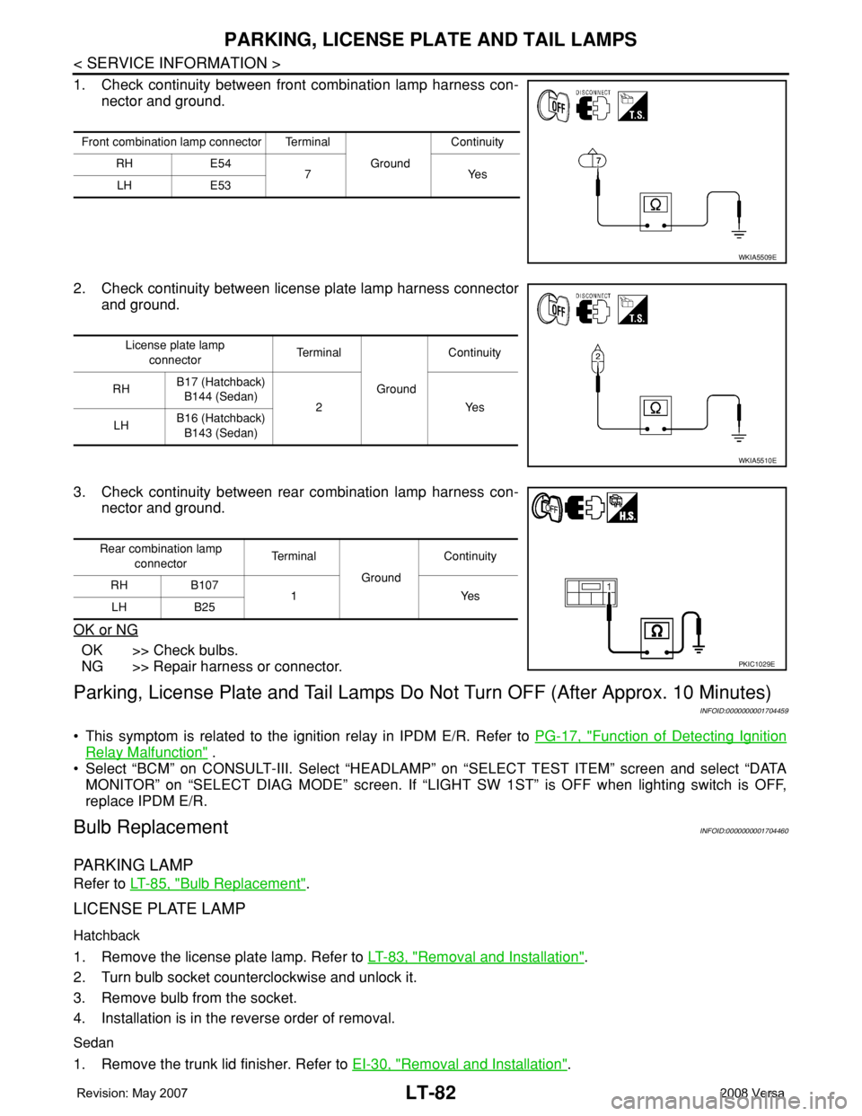
1. Check continuity between front combination lamp harness con-
nector and ground.
2. Check continuity between license plate lamp harness connector
and ground.
3. Check continuity between rear combination lamp harness con-
nector and ground.
OK or NG
OK >> Check bulbs.
NG >> Repair harness or connector.
Parking, License Plate and Tail Lamps Do Not Turn OFF (After Approx. 10 Minutes)
INFOID:0000000001704459
• This symptom is related to the ignition relay in IPDM E/R. Refer to PG-17, "Function of Detecting Ignition
Relay Malfunction" .
• Select “BCM” on CONSULT-III. Select “HEADLAMP” on “SELECT TEST ITEM” screen and select “DATA
MONITOR” on “SELECT DIAG MODE” screen. If “LIGHT SW 1ST” is OFF when lighting switch is OFF,
replace IPDM E/R.
Bulb ReplacementINFOID:0000000001704460
PARKING LAMP
Refer to LT-85, "Bulb Replacement".
LICENSE PLATE LAMP
Hatchback
1. Remove the license plate lamp. Refer to LT-83, "Removal and Installation".
2. Turn bulb socket counterclockwise and unlock it.
3. Remove bulb from the socket.
4. Installation is in the reverse order of removal.
Sedan
1. Remove the trunk lid finisher. Refer to EI-30, "Removal and Installation".
Front combination lamp connector Terminal
GroundContinuity
RH E54
7Yes
LH E53
WKIA5509E
License plate lamp
connectorTe r m i n a l
GroundContinuity
RHB17 (Hatchback)
B144 (Sedan)
2 Yes
LHB16 (Hatchback)
B143 (Sedan)
WKIA5510E
Rear combination lamp
connectorTe r m i n a l
GroundContinuity
RH B107
1Yes
LH B25
PKIC1029E
Page 2242 of 2771

ILLUMINATION
LT-105
< SERVICE INFORMATION >
C
D
E
F
G
H
I
J
L
MA
B
LT
N
O
P
ILLUMINATION
System DescriptionINFOID:0000000001704480
The control of the illumination lamps operation is dependent upon the position of the lighting switch. When the
lighting switch is placed in the 1ST or 2ND position, the BCM (body control module) receives input signal
requesting the illumination lamps to illuminate. This input signal is communicated to IPDM E/R (intelligent
power distribution module engine room) across CAN communication lines. CPU (central processing unit)
located in the IPDM E/R controls the tail lamp relay coil. This relay, when energized, directs power to the illu-
mination lamps, which then illuminate.
Power is supplied at all times
• to ignition relay, located in IPDM E/R,
• to tail lamp relay, located in IPDM E/R,
• through 15A fuse (No. 52, located in IPDM E/R) and
• through 20A fuse (No. 53, located in IPDM E/R)
• to CPU located in IPDM E/R,
• through 40A fusible link (letter g , located in fuse and fusible link box)
• to BCM terminal 70, and
• through 10A fuse [No. 8, located in fuse block (J/B)]
• to BCM terminal 57.
With the ignition switch in the ON or START position, power is supplied
• to ignition relay, located in IPDM E/R, and
• through 10A fuse [No. 6, located in fuse block (J/B)]
• to BCM terminal 38.
With the ignition switch in the ACC or ON position, power is supplied
• through 10A fuse [No. 20, located in fuse block (J/B)]
• to BCM terminal 11.
Ground is supplied
• to BCM terminal 67
• through grounds M57 and M61, and
• to IPDM E/R terminals 39 and 59
• through grounds E15 and E24.
ILLUMINATION OPERATION BY LIGHTING SWITCH
With the lighting switch in the 1ST or 2ND position, BCM receives input signal requesting the illumination
lamps to illuminate. This input signal is communicated to IPDM E/R across CAN communication lines. CPU
located in the IPDM E/R controls the tail lamp relay coil, which, when energized, directs power
• through 10A fuse (No. 37, located in IPDM E/R)
• through IPDM E/R terminal 29
• to microphone terminal 3 (with Bluetooth)
• to illumination control switch terminal 1
• to glove box lamp terminal 1 (with glovebox lamp)
• to audio unit terminal 9
• to front air control terminal 5
• to A/T device terminal 3 (with 4-speed A/T)
• to CVT device terminal 3 (with CVT)
• to hazard switch terminal 3
• to combination meter terminal 12
• to door mirror remote control switch terminal 16, and
Ground is supplied
• to microphone terminal 2 (with Bluetooth)
• to glove box lamp terminal 2 (with glove box lamp), and
• to illumination control switch terminal 3
• through grounds M57 and M61.
The illumination control switch controls illumination intensity by varying the ground to the following
• through illumination control switch terminal 2
• to audio unit terminal 8
• to front air control terminal 6
• to A/T device terminal 4 (with 4-speed A/T)
• to CVT device terminal 3 (with CVT)
• to hazard switch terminal 4
Page 2252 of 2771
LU-2
< SERVICE INFORMATION >
PRECAUTIONS
SERVICE INFORMATION
PRECAUTIONS
Precaution for Supplemental Restraint System (SRS) "AIR BAG" and "SEAT BELT
PRE-TENSIONER"
INFOID:0000000001790697
The Supplemental Restraint System such as “AIR BAG” and “SEAT BELT PRE-TENSIONER”, used along
with a front seat belt, helps to reduce the risk or severity of injury to the driver and front passenger for certain
types of collision. This system includes seat belt switch inputs and dual stage front air bag modules. The SRS
system uses the seat belt switches to determine the front air bag deployment, and may only deploy one front
air bag, depending on the severity of a collision and whether the front occupants are belted or unbelted.
Information necessary to service the system safely is included in the SRS and SB section of this Service Man-
ual.
WARNING:
• To avoid rendering the SRS inoperative, which could increase the risk of personal injury or death in
the event of a collision which would result in air bag inflation, all maintenance must be performed by
an authorized NISSAN/INFINITI dealer.
• Improper maintenance, including incorrect removal and installation of the SRS, can lead to personal
injury caused by unintentional activation of the system. For removal of Spiral Cable and Air Bag
Module, see the SRS section.
• Do not use electrical test equipment on any circuit related to the SRS unless instructed to in this
Service Manual. SRS wiring harnesses can be identified by yellow and/or orange harnesses or har-
ness connectors.
Precaution for Liquid GasketINFOID:0000000001702514
LIQUID GASKET APPLICATION PROCEDURE
1. Remove old liquid gasket adhering to the liquid gasket application surface and the mating surface.
• Remove liquid gasket completely from the liquid gasket application surface, bolts, and bolt holes.
2. Wipe the liquid gasket application surface and the mating surface with white gasoline (lighting and heating
use) to remove adhering moisture, grease and foreign materials.
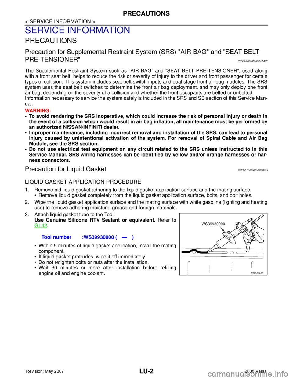
3. Attach liquid gasket tube to the Tool.
Use Genuine Silicone RTV Sealant or equivalent. Refer to
GI-42
.
• Within 5 minutes of liquid gasket application, install the mating
component.
• If liquid gasket protrudes, wipe it off immediately.
• Do not retighten bolts or nuts after the installation.
• Wait 30 minutes or more after installation before refilling
engine oil and engine coolant.Tool number :WS39930000 ( — )
PBIC2160E