2008 NISSAN LATIO key
[x] Cancel search: keyPage 1063 of 2771
![NISSAN LATIO 2008 Service Repair Manual DI-42
< SERVICE INFORMATION >
WARNING CHIME
• through 10A fuse [No. 8, located in the fuse block (J/B)]
• to BCM terminal 57,
• through 10A fuse [No. 13, located in the fuse block (J/B)]
• to NISSAN LATIO 2008 Service Repair Manual DI-42
< SERVICE INFORMATION >
WARNING CHIME
• through 10A fuse [No. 8, located in the fuse block (J/B)]
• to BCM terminal 57,
• through 10A fuse [No. 13, located in the fuse block (J/B)]
• to](/manual-img/5/57360/w960_57360-1062.png)
DI-42
< SERVICE INFORMATION >
WARNING CHIME
• through 10A fuse [No. 8, located in the fuse block (J/B)]
• to BCM terminal 57,
• through 10A fuse [No. 13, located in the fuse block (J/B)]
• to combination meter terminal 27.
With ignition switch in the ON or START position, power is supplied
• through 10A fuse [No. 6, located in the fuse block (J/B)]
• to BCM terminal 38,
• through 10A fuse [No. 3, located in the fuse block (J/B)]
• to combination meter terminal 28.
Ground is supplied
• to BCM terminal 67 and
• to combination meter terminals 21, 22 and 23
• through grounds M57 and M61.
IGNITION KEY WARNING CHIME (WITHOUT INTELLIGENT KEY)
With the key inserted into the key switch, and the ignition switch in the OFF or ACC position, when driver's
door is opened, the warning chime will sound.
• BCM detects key inserted into the ignition switch, and sends key warning signal to combination meter with
CAN communication line.
• When combination meter receives key warning signal, it sounds warning chime.
IGNITION KEY WARNING CHIME (WITH INTELLIGENT KEY)
When Mechanical Key Is Used
With the key inserted into the key switch, and the ignition switch in the LOCK or ACC position, when driver's
door is opened, the warning chime will sound.
• BCM detects key inserted into the ignition switch, and sends key warning signal to combination meter with
CAN communication line.
• When combination meter receives key warning signal, it sounds warning chime.
When Intelligent Key Is Carried With The Driver
Refer to BL-76, "System Description".
LIGHT WARNING CHIME
The warning chime sounds, when driver's door is opened (door switch ON) with lighting switch ON and the
ignition switch is in any position other than ON or START.
NOTE:
BCM detected lighting switch in the 1st or 2nd position, refer to LT-62, "
Combination Switch Reading Func-
tion".
• BCM detects headlamps are illuminated, and sends light warning signal to combination meter with CAN
communication lines.
WKIA5463E
WKIA5464E
Page 1067 of 2771
![NISSAN LATIO 2008 Service Repair Manual DI-46
< SERVICE INFORMATION >
WARNING CHIME
DATA MONITOR
Display Item List
ACTIVE TEST
Display Item List
SELF-DIAG RESULTS
Display Item List
NOTE:
If “CAN communication [U1000]” is indicated, afte NISSAN LATIO 2008 Service Repair Manual DI-46
< SERVICE INFORMATION >
WARNING CHIME
DATA MONITOR
Display Item List
ACTIVE TEST
Display Item List
SELF-DIAG RESULTS
Display Item List
NOTE:
If “CAN communication [U1000]” is indicated, afte](/manual-img/5/57360/w960_57360-1066.png)
DI-46
< SERVICE INFORMATION >
WARNING CHIME
DATA MONITOR
Display Item List
ACTIVE TEST
Display Item List
SELF-DIAG RESULTS
Display Item List
NOTE:
If “CAN communication [U1000]” is indicated, after printing the monitor item, go to “LAN system”. Refer to
LAN-15, "
Trouble Diagnosis Flow Chart".
Trouble DiagnosisINFOID:0000000001704526
HOW TO PERFORM TROUBLE DIAGNOSIS
1. Confirm the symptom and customer complaint.
2. Understand the outline of system. Refer to DI-41, "
System Description".
3. Perform the preliminary inspection. Refer to "PRELIMINARY INSPECTION".
4. According to symptom chart, repair or replace the cause of the malfunction. Refer to "SYMPTOM
CHART".
5. Does warning chime system operate normally? If it operates normally, GO TO 6. If not, GO TO 4.
6. Inspection End.
PRELIMINARY INSPECTION
BCM diagnostic
test itemDiagnostic mode Description
Inspection by partWORK SUPPORTSupports inspections and adjustments. Commands are transmitted to the BCM for
setting the status suitable for required operation, input/output signals are received
from the BCM and received data is displayed.
DATA MONITOR Displays BCM input/output data in real time.
ACTIVE TEST Operation of electrical loads can be checked by sending drive signal to them.
SELF-DIAG RESULTS Displays BCM self-diagnosis results.
CAN DIAG SUPPORT MNTR The result of transmit/receive diagnosis of CAN communication can be read.
ECU PART NUMBER BCM part number can be read.
CONFIGURATION Performs BCM configuration read/write functions.
Monitored item ALL SIGNALSSELECTION
FROM MENUContents
IGN ON SW X X Indicates [ON/OFF] condition of ignition switch.
KEY ON SW X X Indicates [ON/OFF] condition of key switch.
DOOR SW-DR X X Indicates [ON/OFF] condition of front door switch LH.
LIGHT SW 1ST X X Indicates [ON/OFF] condition of lighting switch.
BUCKLE SW X X Indicates [ON/OFF] condition of seat belt buckle switch LH.
Test item Malfunction is detected when···
IGN KEY WARN ALM This test is able to check key warning chime operation.
LIGHT WARN ALM This test is able to check light warning chime operation.
SEAT BELT WARN TEST This test is able to check seat belt warning chime operation.
Display item [Code] Malfunction is detected when...
CAN communication [U1000] Malfunction is detected in CAN communication.
Page 1068 of 2771
WARNING CHIME
DI-47
< SERVICE INFORMATION >
C
D
E
F
G
H
I
J
L
MA
B
DI
N
O
P
1.CHECK BCM
Perform self-diagnosis of BCM. Refer to DI-45, "
CONSULT-III Function (BCM)".
Self
-diagnostic results content
No malfunction detected>>GO TO 2.
Malfunction detected>> Check applicable parts, and repair or replace corresponding parts.
2.CHECK COMBINATION METER
Perform self-diagnosis of combination meter. Refer to DI-13, "
CONSULT-III Function (METER/M&A)".
Self
-diagnostic results content
No malfunction detected>> Inspection End.
Malfunction detected>> Check applicable parts, and repair or replace corresponding parts.
SYMPTOM CHART
Combination Meter Buzzer Circuit InspectionINFOID:0000000001704527
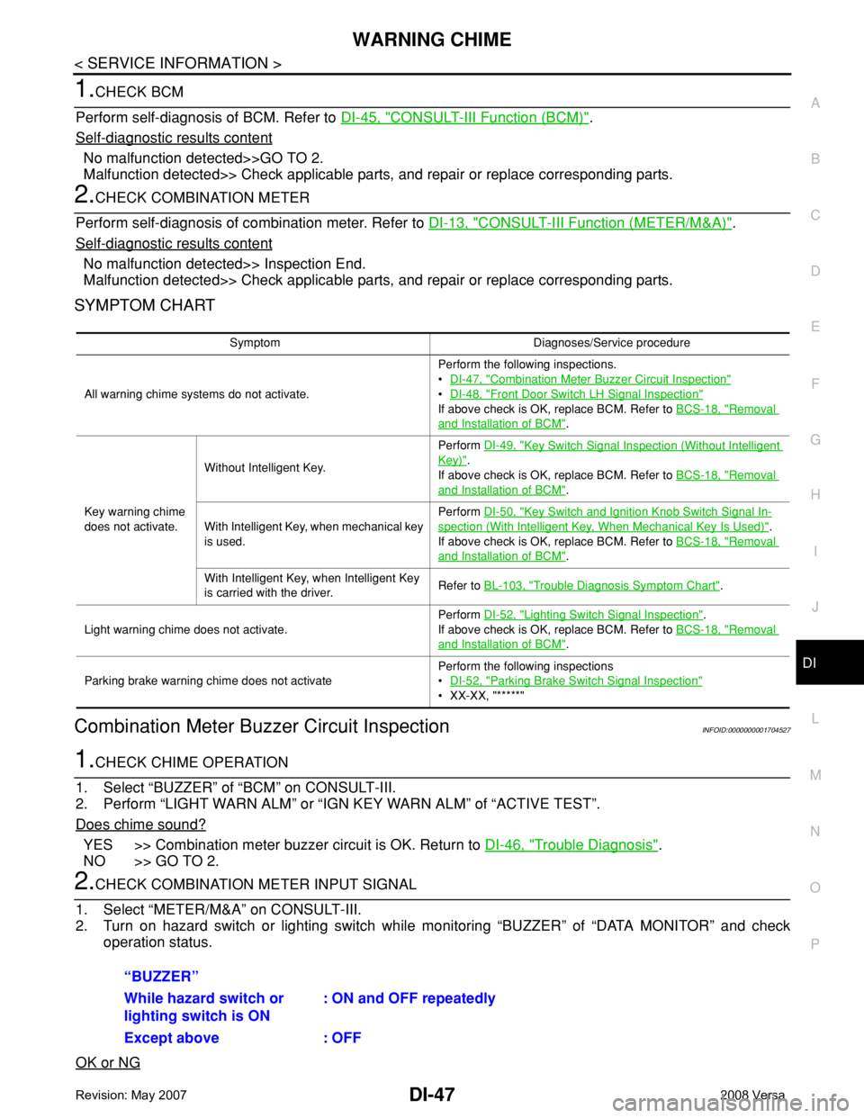
1.CHECK CHIME OPERATION
1. Select “BUZZER” of “BCM” on CONSULT-III.
2. Perform “LIGHT WARN ALM” or “IGN KEY WARN ALM” of “ACTIVE TEST”.
Does chime sound?
YES >> Combination meter buzzer circuit is OK. Return to DI-46, "Trouble Diagnosis".
NO >> GO TO 2.
2.CHECK COMBINATION METER INPUT SIGNAL
1. Select “METER/M&A” on CONSULT-III.
2. Turn on hazard switch or lighting switch while monitoring “BUZZER” of “DATA MONITOR” and check
operation status.
OK or NG
Symptom Diagnoses/Service procedure
All warning chime systems do not activate.Perform the following inspections.
•DI-47, "
Combination Meter Buzzer Circuit Inspection"
•DI-48, "Front Door Switch LH Signal Inspection"
If above check is OK, replace BCM. Refer to BCS-18, "Removal
and Installation of BCM".
Key warning chime
does not activate.Without Intelligent Key.Perform DI-49, "
Key Switch Signal Inspection (Without Intelligent
Key)".
If above check is OK, replace BCM. Refer to BCS-18, "
Removal
and Installation of BCM".
With Intelligent Key, when mechanical key
is used.Perform DI-50, "
Key Switch and Ignition Knob Switch Signal In-
spection (With Intelligent Key, When Mechanical Key Is Used)".
If above check is OK, replace BCM. Refer to BCS-18, "
Removal
and Installation of BCM".
With Intelligent Key, when Intelligent Key
is carried with the driver.Refer to BL-103, "
Trouble Diagnosis Symptom Chart".
Light warning chime does not activate.Perform DI-52, "
Lighting Switch Signal Inspection".
If above check is OK, replace BCM. Refer to BCS-18, "
Removal
and Installation of BCM".
Parking brake warning chime does not activatePerform the following inspections
•DI-52, "
Parking Brake Switch Signal Inspection"
• XX-XX, "*****"
“BUZZER”
While hazard switch or
lighting switch is ON : ON and OFF repeatedly
Except above : OFF
Page 1070 of 2771
WARNING CHIME
DI-49
< SERVICE INFORMATION >
C
D
E
F
G
H
I
J
L
MA
B
DI
N
O
P
OK >> Replace BCM. Refer to BCS-18, "Removal and Installation of BCM".
NG >> Replace front door switch LH.
Key Switch Signal Inspection (Without Intelligent Key)INFOID:0000000001704529
1.CHECK FUSE
Check if the key switch and key lock solenoid 10A fuse [No. 14, located in the fuse block (J/B)] is blown.
OK or NG
OK >> GO TO 2.
NG >> Be sure to repair the cause of malfunction before installing new fuse. Refer to PG-3
.
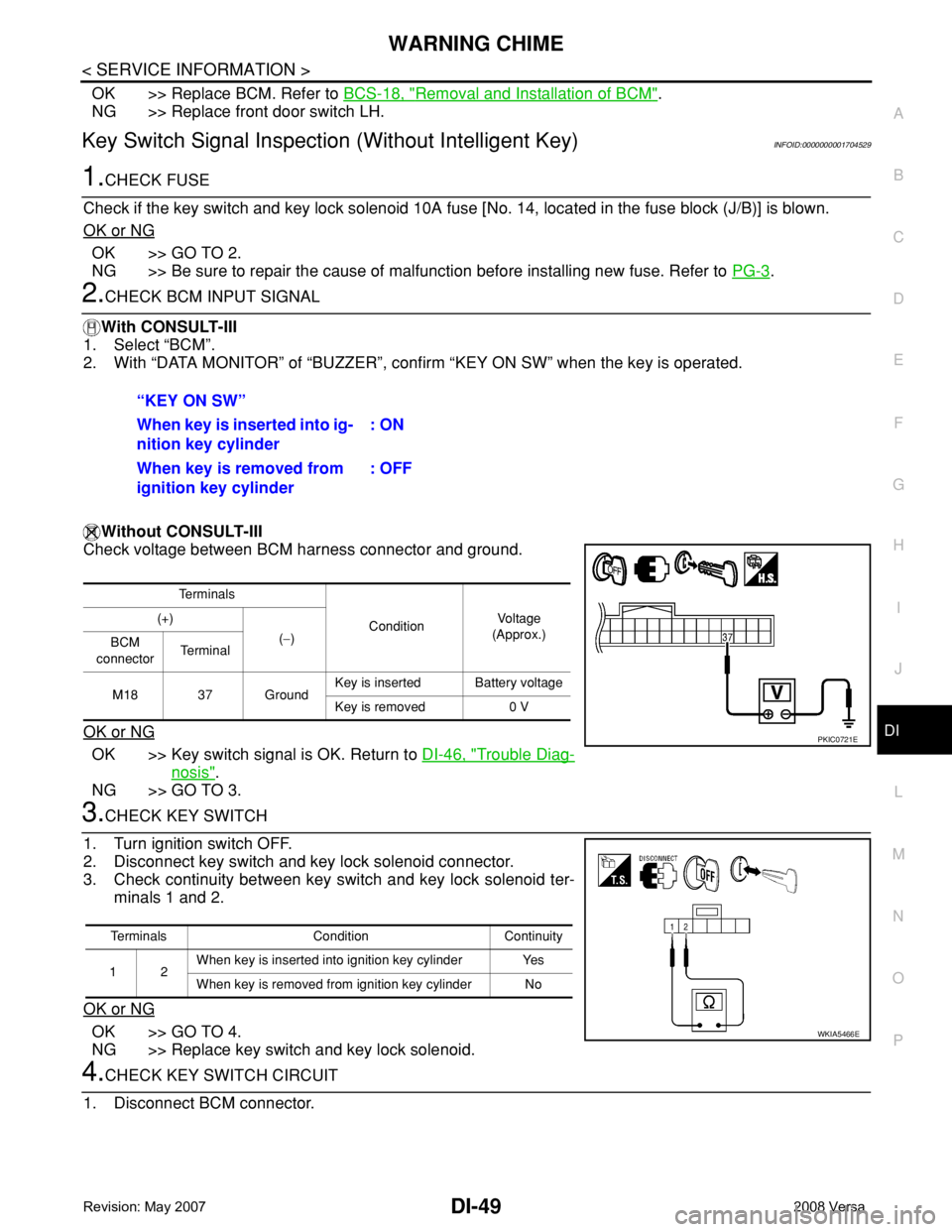
2.CHECK BCM INPUT SIGNAL
With CONSULT-III
1. Select “BCM”.
2. With “DATA MONITOR” of “BUZZER”, confirm “KEY ON SW” when the key is operated.
Without CONSULT-III
Check voltage between BCM harness connector and ground.
OK or NG
OK >> Key switch signal is OK. Return to DI-46, "Trouble Diag-
nosis".
NG >> GO TO 3.
3.CHECK KEY SWITCH
1. Turn ignition switch OFF.
2. Disconnect key switch and key lock solenoid connector.
3. Check continuity between key switch and key lock solenoid ter-
minals 1 and 2.
OK or NG
OK >> GO TO 4.
NG >> Replace key switch and key lock solenoid.
4.CHECK KEY SWITCH CIRCUIT
1. Disconnect BCM connector.“KEY ON SW”
When key is inserted into ig-
nition key cylinder: ON
When key is removed from
ignition key cylinder: OFF
Te r m i n a l s
ConditionVoltag e
(Approx.) (+)
(−)
BCM
connectorTe r m i n a l
M18 37 GroundKey is inserted Battery voltage
Key is removed 0 V
PKIC0721E
Terminals Condition Continuity
12When key is inserted into ignition key cylinder Yes
When key is removed from ignition key cylinder No
WKIA5466E
Page 1071 of 2771
DI-50
< SERVICE INFORMATION >
WARNING CHIME
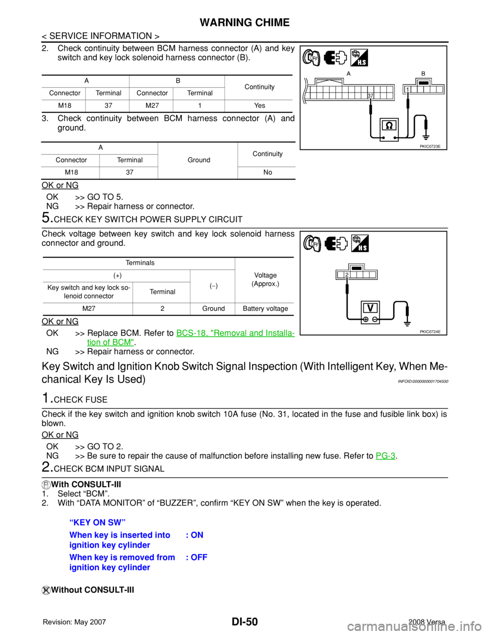
2. Check continuity between BCM harness connector (A) and key
switch and key lock solenoid harness connector (B).
3. Check continuity between BCM harness connector (A) and
ground.
OK or NG
OK >> GO TO 5.
NG >> Repair harness or connector.
5.CHECK KEY SWITCH POWER SUPPLY CIRCUIT
Check voltage between key switch and key lock solenoid harness
connector and ground.
OK or NG
OK >> Replace BCM. Refer to BCS-18, "Removal and Installa-
tion of BCM".
NG >> Repair harness or connector.
Key Switch and Ignition Knob Switch Signal Inspection (With Intelligent Key, When Me-
chanical Key Is Used)
INFOID:0000000001704530
1.CHECK FUSE
Check if the key switch and ignition knob switch 10A fuse (No. 31, located in the fuse and fusible link box) is
blown.
OK or NG
OK >> GO TO 2.
NG >> Be sure to repair the cause of malfunction before installing new fuse. Refer to PG-3
.
2.CHECK BCM INPUT SIGNAL
With CONSULT-III
1. Select “BCM”.
2. With “DATA MONITOR” of “BUZZER”, confirm “KEY ON SW” when the key is operated.
Without CONSULT-III
AB
Continuity
Connector Terminal Connector Terminal
M18 37 M27 1 Yes
A
GroundContinuity
Connector Terminal
M18 37 No
PKIC0723E
Te r m i n a l s
Voltage
(Approx.) (+)
(−)
Key switch and key lock so-
lenoid connectorTe r m i n a l
M27 2 Ground Battery voltage
PKIC0724E
“KEY ON SW”
When key is inserted into
ignition key cylinder: ON
When key is removed from
ignition key cylinder: OFF
Page 1072 of 2771
WARNING CHIME
DI-51
< SERVICE INFORMATION >
C
D
E
F
G
H
I
J
L
MA
B
DI
N
O
P
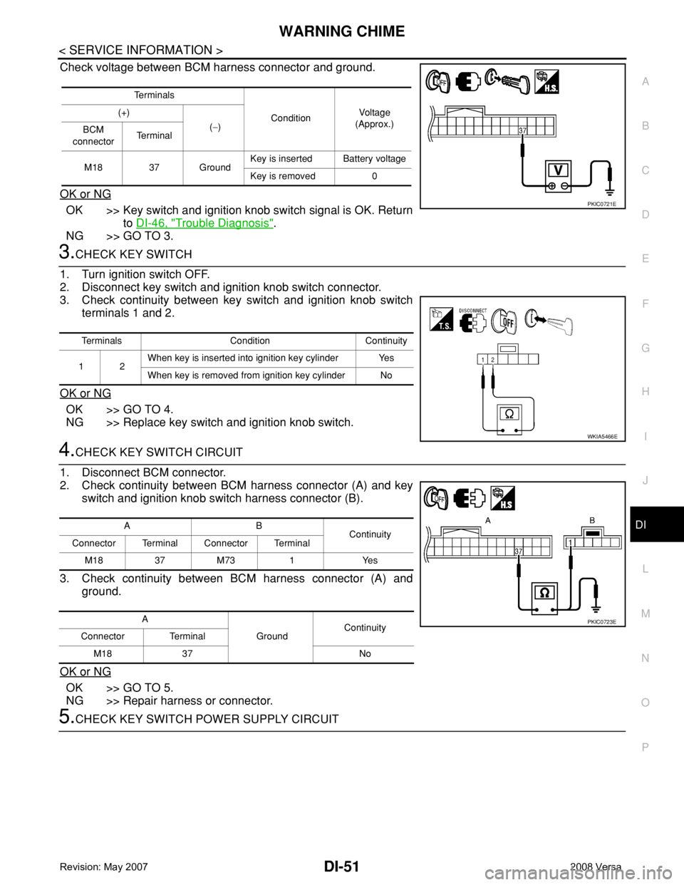
Check voltage between BCM harness connector and ground.
OK or NG
OK >> Key switch and ignition knob switch signal is OK. Return
to DI-46, "
Trouble Diagnosis".
NG >> GO TO 3.
3.CHECK KEY SWITCH
1. Turn ignition switch OFF.
2. Disconnect key switch and ignition knob switch connector.
3. Check continuity between key switch and ignition knob switch
terminals 1 and 2.
OK or NG
OK >> GO TO 4.
NG >> Replace key switch and ignition knob switch.
4.CHECK KEY SWITCH CIRCUIT
1. Disconnect BCM connector.
2. Check continuity between BCM harness connector (A) and key
switch and ignition knob switch harness connector (B).
3. Check continuity between BCM harness connector (A) and
ground.
OK or NG
OK >> GO TO 5.
NG >> Repair harness or connector.
5.CHECK KEY SWITCH POWER SUPPLY CIRCUIT
Te r m i n a l s
ConditionVol tag e
(Approx.) (+)
(−)
BCM
connectorTe r m i n a l
M18 37 GroundKey is inserted Battery voltage
Key is removed 0
PKIC0721E
Terminals Condition Continuity
12When key is inserted into ignition key cylinder Yes
When key is removed from ignition key cylinder No
WKIA5466E
AB
Continuity
Connector Terminal Connector Terminal
M1837M73 1 Yes
A
GroundContinuity
Connector Terminal
M18 37 No
PKIC0723E
Page 1073 of 2771
DI-52
< SERVICE INFORMATION >
WARNING CHIME
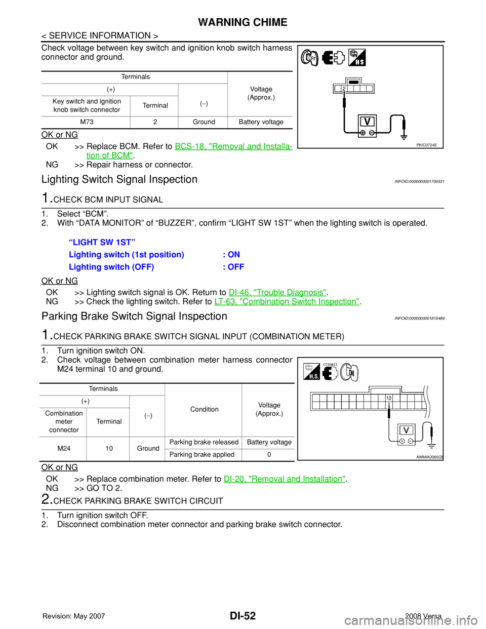
Check voltage between key switch and ignition knob switch harness
connector and ground.
OK or NG
OK >> Replace BCM. Refer to BCS-18, "Removal and Installa-
tion of BCM".
NG >> Repair harness or connector.
Lighting Switch Signal InspectionINFOID:0000000001704531
1.CHECK BCM INPUT SIGNAL
1. Select “BCM”.
2. With “DATA MONITOR” of “BUZZER”, confirm “LIGHT SW 1ST” when the lighting switch is operated.
OK or NG
OK >> Lighting switch signal is OK. Return to DI-46, "Trouble Diagnosis".
NG >> Check the lighting switch. Refer to LT-63, "
Combination Switch Inspection".
Parking Brake Switch Signal InspectionINFOID:0000000001815489
1.CHECK PARKING BRAKE SWITCH SIGNAL INPUT (COMBINATION METER)
1. Turn ignition switch ON.
2. Check voltage between combination meter harness connector
M24 terminal 10 and ground.
OK or NG
OK >> Replace combination meter. Refer to DI-20, "Removal and Installation".
NG >> GO TO 2.
2.CHECK PARKING BRAKE SWITCH CIRCUIT
1. Turn ignition switch OFF.
2. Disconnect combination meter connector and parking brake switch connector.
Te r m i n a l s
Vo l ta g e
(Approx.) (+)
(−) Key switch and ignition
knob switch connector Te r m i n a l
M73 2 Ground Battery voltage
PKIC0724E
“LIGHT SW 1ST”
Lighting switch (1st position) : ON
Lighting switch (OFF) : OFF
Te r m i n a l s
ConditionVoltag e
(Approx.) (+)
(−) Combination
meter
connectorTe r m i n a l
M24 10 GroundParking brake released Battery voltage
Parking brake applied 0
AWMIA0066GB
Page 1119 of 2771
NVIS (NISSAN VEHICLE IMMOBILIZER SYSTEM-NATS)
EC-45
< SERVICE INFORMATION >
C
D
E
F
G
H
I
J
K
L
MA
EC
N
P O
NVIS (NISSAN VEHICLE IMMOBILIZER SYSTEM-NATS)
DescriptionINFOID:0000000001702572
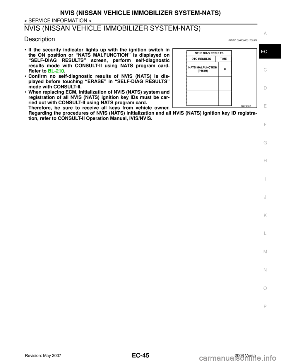
•If the security indicator lights up with the ignition switch in
the ON position or “NATS MALFUNCTION” is displayed on
“SELF-DIAG RESULTS” screen, perform self-diagnostic
results mode with CONSULT-II using NATS program card.
Refer to BL-210
.
•Confirm no self-diagnostic results of NVIS (NATS) is dis-
played before touching “ERASE” in “SELF-DIAG RESULTS”
mode with CONSULT-II.
•When replacing ECM, initialization of NVIS (NATS) system and
registration of all NVIS (NATS) ignition key IDs must be car-
ried out with CONSULT-II using NATS program card.
Therefore, be sure to receive all keys from vehicle owner.
Regarding the procedures of NVIS (NATS) initialization and all NVIS (NATS) ignition key ID registra-
tion, refer to CONSULT-II Operation Manual, IVIS/NVIS.
SEF543X