Page 2199 of 2771
LT-62
< SERVICE INFORMATION >
COMBINATION SWITCH
COMBINATION SWITCH
Wiring Diagram - COMBSW -INFOID:0000000001704432
Combination Switch Reading FunctionINFOID:0000000001704433
For details, refer to BCS-3, "System Description" .
LKWA0333E
Page 2200 of 2771

COMBINATION SWITCH
LT-63
< SERVICE INFORMATION >
C
D
E
F
G
H
I
J
L
MA
B
LT
N
O
P
Terminal and Reference Value for BCMINFOID:0000000001704434
Refer to BCS-11, "Terminal and Reference Value for BCM" .
CONSULT-III Function (BCM)INFOID:0000000001704435
Refer to LT- 11 , "CONSULT-III Function (BCM)" .
Combination Switch InspectionINFOID:0000000001704436
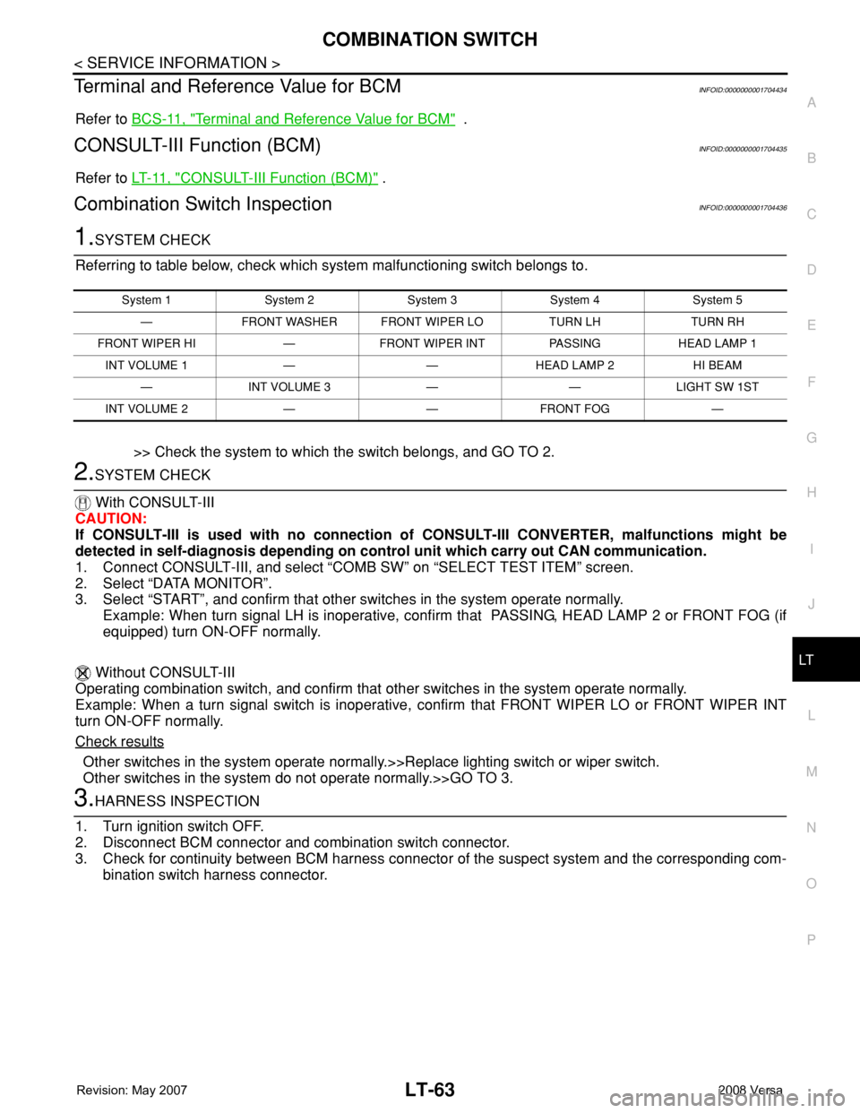
1.SYSTEM CHECK
Referring to table below, check which system malfunctioning switch belongs to.
>> Check the system to which the switch belongs, and GO TO 2.
2.SYSTEM CHECK
With CONSULT-III
CAUTION:
If CONSULT-III is used with no connection of CONSULT-III CONVERTER, malfunctions might be
detected in self-diagnosis depending on control unit which carry out CAN communication.
1. Connect CONSULT-III, and select “COMB SW” on “SELECT TEST ITEM” screen.
2. Select “DATA MONITOR”.
3. Select “START”, and confirm that other switches in the system operate normally.
Example: When turn signal LH is inoperative, confirm that PASSING, HEAD LAMP 2 or FRONT FOG (if
equipped) turn ON-OFF normally.
Without CONSULT-III
Operating combination switch, and confirm that other switches in the system operate normally.
Example: When a turn signal switch is inoperative, confirm that FRONT WIPER LO or FRONT WIPER INT
turn ON-OFF normally.
Check results
Other switches in the system operate normally.>>Replace lighting switch or wiper switch.
Other switches in the system do not operate normally.>>GO TO 3.
3.HARNESS INSPECTION
1. Turn ignition switch OFF.
2. Disconnect BCM connector and combination switch connector.
3. Check for continuity between BCM harness connector of the suspect system and the corresponding com-
bination switch harness connector.
System 1 System 2 System 3 System 4 System 5
— FRONT WASHER FRONT WIPER LO TURN LH TURN RH
FRONT WIPER HI — FRONT WIPER INT PASSING HEAD LAMP 1
INT VOLUME 1 — — HEAD LAMP 2 HI BEAM
— INT VOLUME 3 — — LIGHT SW 1ST
INT VOLUME 2 — — FRONT FOG —
Page 2201 of 2771
LT-64
< SERVICE INFORMATION >
COMBINATION SWITCH
4. Check for continuity between of BCM harness connector in suspect system and ground.
OK or NG
OK >> GO TO 4.
NG >> Check harness between BCM and combination switch for open or short circuit.
4.CHECK BCM OUTPUT TERMINAL
1. Connect BCM and combination switch connectors.
2. Turn ignition switch ON.
3. Turn lighting switch and wiper switch to OFF position.
4. Set wiper dial position 4.
5. Check BCM output terminal voltage waveform of suspect sys-
tem.
Suspect
systemAB
Continuity
Connector Terminal Connector Terminal
1
M18Input 1 6
M286
Ye s Output 1 36 1
2Input 2 5 7
Output 2 35 2
3Input 3 4 10
Output 3 34 3
4Input 4 3 9
Output 4 33 4
5Input 5 2 8
Output 5 32 5
Suspect
systemBCM
Continuity
Connector Terminal
1
M18Input 1 6
Ground No Output 1 36
2Input 2 5
Output 2 35
3Input 3 4
Output 3 34
4Input 4 3
Output 4 33
5Input 5 2
Output 5 32
WKIA5497E
WKIA5500E
PKIC1020E
Page 2202 of 2771
COMBINATION SWITCH
LT-65
< SERVICE INFORMATION >
C
D
E
F
G
H
I
J
L
MA
B
LT
N
O
P
OK or NG
OK >> Open circuit in combination switch, GO TO 5.
NG >> Replace BCM. Refer to BCS-18, "
Removal and Installation of BCM" .
5.COMBINATION SWITCH INSPECTION
Referring to table below, perform combination switch inspection.
>> INSPECTION END
Removal and InstallationINFOID:0000000001704437
Refer to LT- 6 0 .
Suspect
systemTe r m i n a l
Reference value (+)
(−) Combination
switch
connectorTe r m i n a l
1
M281
Ground1.2V 22
33
44
55
1.2V
PKIB4958J
PKIB8643J
Procedure
12 3 4 5 6 7
Re-
place
lighting
switchConfirm
check
resultsOK INSPECTION END
Confirm
check
resultsOK INSPECTION END
Confirm
check
resultsOK INSPECTION END
NG Replace wiper switch NG Replace switch base NG Confirm symptom again
Page 2203 of 2771
LT-66
< SERVICE INFORMATION >
STOP LAMP
STOP LAMP
Wiring Diagram - STOP/LINFOID:0000000001704438
HATCHBACK
WKWA5833E
Page 2204 of 2771
STOP LAMP
LT-67
< SERVICE INFORMATION >
C
D
E
F
G
H
I
J
L
MA
B
LT
N
O
P
Wiring Diagram - STOP/LINFOID:0000000001704439
SEDAN
Bulb Replacement for High-Mounted Stop LampINFOID:0000000001704440
HATCHBACK
The LED element is not serviced separately, the high-mounted stop lamp must be replaced as an assembly.
Refer to LT-68, "
Removal and Installation of High-Mounted Stop Lamp".
ALLWA0128GB
Page 2205 of 2771
LT-68
< SERVICE INFORMATION >
STOP LAMP
SEDAN
1. Remove the high-mounted stop lamp bulb socket (1) and
remove the high-mounted stop lamp (2).
2. Installation is in the reverse order of removal.
Bulb Replacement for Rear Combination Lamp for Stop LampINFOID:0000000001704441
Refer to LT-85, "Bulb Replacement".
Removal and Installation of High-Mounted Stop LampINFOID:0000000001704442
HATCHBACK
Removal
1. Remove the rear hatch finish panel. Refer to EI-51.
2. Disconnect the high-mounted stop lamp connector.
3. Remove the nuts and remove the high-mounted stop lamp from
rear hatch.
Installation
Installation is in the reverse order of removal.
CAUTION:
Properly seal the high-mounted stop lamp base to the rear hatch to prevent water leaks.
SEDAN
Removal
1. Remove the rear parcel shelf. Refer to EI-42, "Removal and Installation".
2. Remove the high-mounted stop lamp screws (A) and remove
the high-mounted stop lamp (1).
PKIC1021E
SKIB7594E
PKIC1022E
Page 2206 of 2771
STOP LAMP
LT-69
< SERVICE INFORMATION >
C
D
E
F
G
H
I
J
L
MA
B
LT
N
O
P
3. Remove the high-mounted stop lamp finisher screws (A) and
remove the high-mounted stop lamp finisher (1).
Installation
Installation is in the reverse order of removal.
Removal and Installation of Rear Combination Lamp for Stop LampINFOID:0000000001704443
Refer to LT-86, "Removal and Installation".
PKIC1023E