2008 NISSAN LATIO engine
[x] Cancel search: enginePage 835 of 2771
CO-18
< SERVICE INFORMATION >
THERMOSTAT
• If out of the specification, replace thermostat.
INSTALLATION
Installation is in the reverse order of removal.
Thermostat
CAUTION:
Replace the rubber ring with a new one.
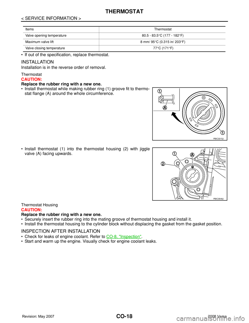
• Install thermostat while making rubber ring (1) groove fit to thermo-
stat flange (A) around the whole circumference.
• Install thermostat (1) into the thermostat housing (2) with jiggle
valve (A) facing upwards.
Thermostat Housing
CAUTION:
Replace the rubber ring with a new one.
• Securely insert the rubber ring into the mating groove of thermostat housing and install it.
• Install the thermostat housing to the cylinder block without displacing the gasket from the gasket position.
INSPECTION AFTER INSTALLATION
• Check for leaks of engine coolant. Refer to CO-8, "Inspection".
• Start and warm up the engine. Visually check for engine coolant leaks.
ItemsThermostat
Valve opening temperature 80.5 - 83.5°C (177 - 182°F)
Maximum valve lift 8 mm/ 95°C (0.315 in/ 203°F)
Valve closing temperature 77°C (171°F)
PBIC3315J
PBIC3548J
Page 836 of 2771
WATER OUTLET AND WATER CONTROL VALVE
CO-19
< SERVICE INFORMATION >
C
D
E
F
G
H
I
J
K
L
MA
CO
N
P O
WATER OUTLET AND WATER CONTROL VALVE
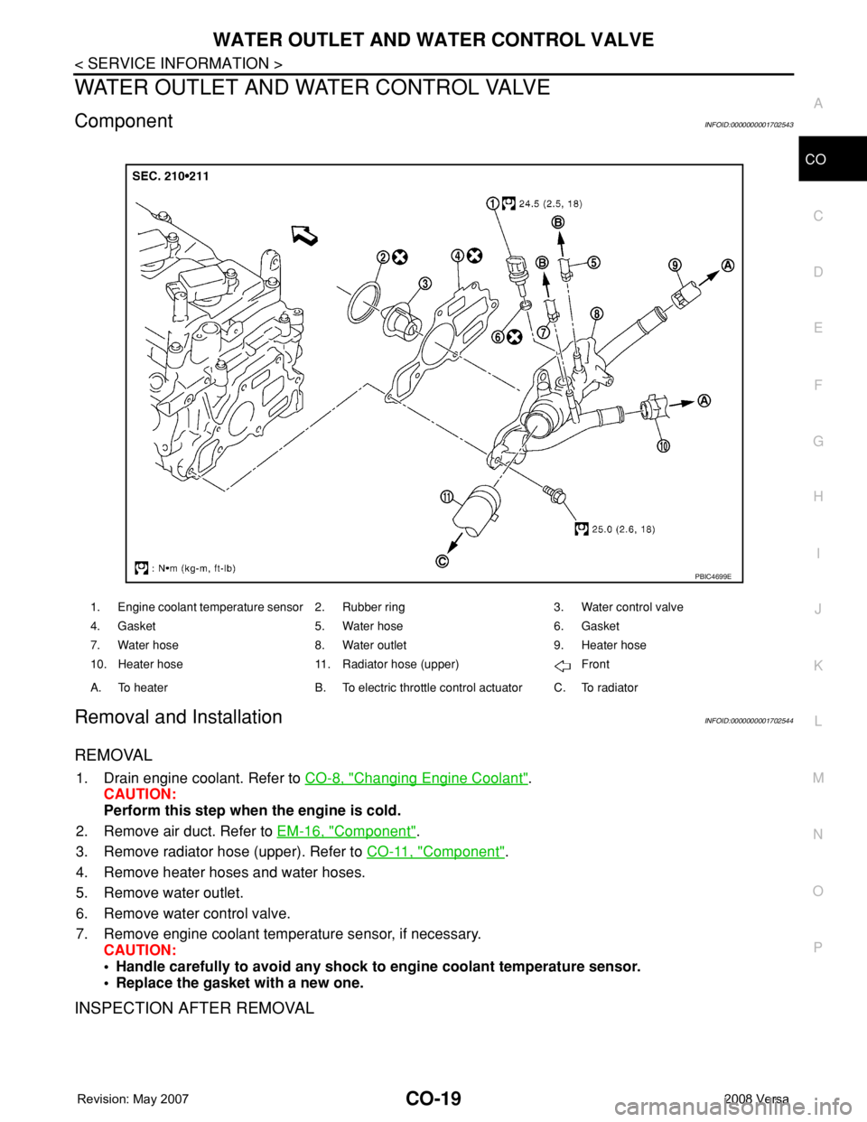
ComponentINFOID:0000000001702543
Removal and InstallationINFOID:0000000001702544
REMOVAL
1. Drain engine coolant. Refer to CO-8, "Changing Engine Coolant".
CAUTION:
Perform this step when the engine is cold.
2. Remove air duct. Refer to EM-16, "
Component".
3. Remove radiator hose (upper). Refer to CO-11, "
Component".
4. Remove heater hoses and water hoses.
5. Remove water outlet.
6. Remove water control valve.
7. Remove engine coolant temperature sensor, if necessary.
CAUTION:
• Handle carefully to avoid any shock to engine coolant temperature sensor.
• Replace the gasket with a new one.
INSPECTION AFTER REMOVAL
1. Engine coolant temperature sensor 2. Rubber ring 3. Water control valve
4. Gasket 5. Water hose 6. Gasket
7. Water hose 8. Water outlet 9. Heater hose
10. Heater hose 11. Radiator hose (upper) Front
A. To heater B. To electric throttle control actuator C. To radiator
PBIC4699E
Page 838 of 2771
WATER OUTLET AND WATER CONTROL VALVE
CO-21
< SERVICE INFORMATION >
C
D
E
F
G
H
I
J
K
L
MA
CO
N
P O
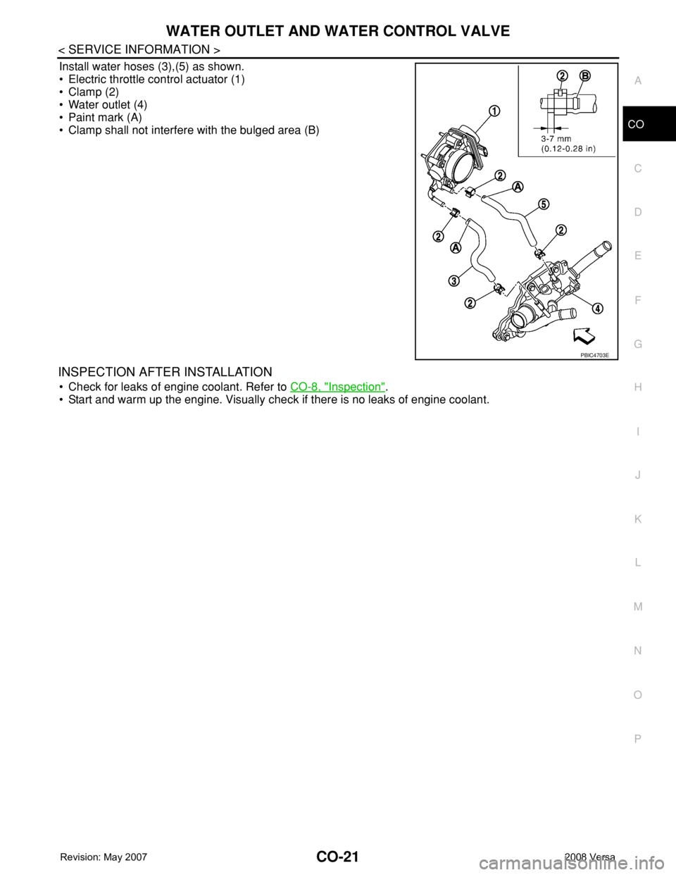
Install water hoses (3),(5) as shown.
• Electric throttle control actuator (1)
• Clamp (2)
• Water outlet (4)
• Paint mark (A)
• Clamp shall not interfere with the bulged area (B)
INSPECTION AFTER INSTALLATION
• Check for leaks of engine coolant. Refer to CO-8, "Inspection".
• Start and warm up the engine. Visually check if there is no leaks of engine coolant.
PBIC4703E
Page 839 of 2771

CO-22
< SERVICE INFORMATION >
SERVICE DATA AND SPECIFICATIONS (SDS)
SERVICE DATA AND SPECIFICATIONS (SDS)
Standard and LimitINFOID:0000000001702545
CAPACITY
Unit: (US qt, lmp qt)
THERMOSTAT
WATER CONTROL VALVE
RADIATOR
Unit: kPa (bar, kg/cm2, psi)
Engine coolant capacity (with reservoir tank at “MAX” level) Approx. 6.8 (7 1/4, 6.0)
Valve opening temperature 80.5 - 83.5°C (177 - 182°F)
Maximum valve lift 8 mm/ 95°C (0.315 in/ 203°F)
Valve closing temperature 77°C (171°F)
Valve opening temperature 93.5 - 96.5°C (200 - 206°F)
Maximum valve lift 8 mm/ 108°C (0.315 in/ 226°F)
Valve closing temperature 90°C (194°F)
Cap relief pressureStandard 78 - 98 (0.78 - 0.98, 0.8 - 1.0, 11- 14)
Limit 59 (0.59, 0.6, 9)
Leakage test pressure 157 (1.57, 1.6, 23)
Page 840 of 2771
CVT-1
TRANSMISSION/TRANSAXLE
D
E
F
G
H
I
J
K
L
M
SECTION CVT
A
B
CVT
N
O
P
CONTENTS
CVT
SERVICE INFORMATION ............................5
INDEX FOR DTC .................................................5
Alphabetical Index .....................................................5
DTC No. Index ..........................................................5
PRECAUTIONS ...................................................7
Precaution for Supplemental Restraint System
(SRS) "AIR BAG" and "SEAT BELT PRE-TEN-
SIONER" ...................................................................
7
Precaution Necessary for Steering Wheel Rota-
tion After Battery Disconnect .....................................
7
Precaution for On Board Diagnosis (OBD) System
of CVT and Engine ....................................................
7
Service After Replacing TCM and Transaxle As-
sembly .......................................................................
8
Removal and Installation Procedure for CVT Unit
Connector ..................................................................
9
Precaution ...............................................................10
Service Notice or Precaution ...................................11
PREPARATION ..................................................12
Special Service Tool ...............................................12
Commercial Service Tool ........................................12
CVT FLUID .........................................................13
Checking CVT Fluid ................................................13
Changing CVT Fluid ................................................14
CVT Fluid Cooler Cleaning .....................................14
CVT SYSTEM .....................................................18
Cross-Sectional View - RE0F08A ...........................18
Control System ........................................................19
Hydraulic Control System ........................................20
TCM Function ..........................................................20
CAN Communication ...............................................21
Input/Output Signal of TCM .....................................22
Line Pressure and Secondary Pressure Control .....22
Shift Control ............................................................23
Lock-up and Select Control .....................................24
Control Valve ...........................................................25
ON BOARD DIAGNOSTIC (OBD) SYSTEM ....26
Introduction ..............................................................26
OBD-II Function for CVT System ............................26
One or Two Trip Detection Logic of OBD-II .............26
OBD-II Diagnostic Trouble Code (DTC) ..................26
Malfunction Indicator Lamp (MIL) ............................27
TROUBLE DIAGNOSIS ....................................29
DTC Inspection Priority Chart ..................................29
Fail-Safe ..................................................................29
How to Perform Trouble Diagnosis for Quick and
Accurate Repair .......................................................
30
CVT Electrical Parts Location ..................................35
Circuit Diagram ........................................................36
Inspections before Trouble Diagnosis .....................36
Road Test ................................................................40
Check before Engine Is Started ...............................41
Check at Idle ............................................................41
Cruise Test ..............................................................43
Vehicle Speed When Shifting Gears .......................45
TCM Terminal and Reference Value .......................45
CONSULT-III Function (TRANSMISSION) ..............47
Diagnosis Procedure without CONSULT-III ............55
DTC U1000 CAN COMMUNICATION LINE .....56
Description ...............................................................56
On Board Diagnosis Logic .......................................56
Possible Cause ........................................................56
DTC Confirmation Procedure ..................................56
Wiring Diagram - CVT - CAN ...................................57
Diagnosis Procedure ...............................................58
DTC U1010 TRANSMISSION CONTROL
MODULE (CAN) ................................................
59
Description ...............................................................59
On Board Diagnosis Logic .......................................59
Possible Cause ........................................................59
DTC Confirmation Procedure ..................................59
Diagnosis Procedure ...............................................59
DTC P0615 START SIGNAL CIRCUIT .............60
Page 841 of 2771

CVT-2
Description ..............................................................60
CONSULT-III Reference Value in Data Monitor
Mode .......................................................................
60
On Board Diagnosis Logic ......................................60
Possible Cause .......................................................60
DTC Confirmation Procedure .................................60
Wiring Diagram - CVT - STSIG ...............................61
Diagnosis Procedure ..............................................62
DTC P0703 STOP LAMP SWITCH CIRCUIT ....63
Description ..............................................................63
CONSULT-III Reference Value in Data Monitor
Mode .......................................................................
63
On Board Diagnosis Logic ......................................63
Possible Cause .......................................................63
DTC Confirmation Procedure .................................63
Diagnosis Procedure ..............................................63
DTC P0705 PARK/NEUTRAL POSITION
SWITCH .............................................................
65
Description ..............................................................65
CONSULT-III Reference Value in Data Monitor
Mode .......................................................................
65
On Board Diagnosis Logic ......................................65
Possible Cause .......................................................65
DTC Confirmation Procedure .................................65
Wiring Diagram - CVT - PNP/SW ...........................67
Diagnosis Procedure ..............................................68
Component Inspection ............................................70
DTC P0710 CVT FLUID TEMPERATURE
SENSOR CIRCUIT .............................................
71
Description ..............................................................71
CONSULT-III Reference Value in Data Monitor
Mode .......................................................................
71
On Board Diagnosis Logic ......................................71
Possible Cause .......................................................71
DTC Confirmation Procedure .................................71
Wiring Diagram - CVT - FTS ...................................72
Diagnosis Procedure ..............................................73
Component Inspection ............................................74
DTC P0715 INPUT SPEED SENSOR CIR-
CUIT (PRI SPEED SENSOR) ............................
76
Description ..............................................................76
CONSULT-III Reference Value in Data Monitor
Mode .......................................................................
76
On Board Diagnosis Logic ......................................76
Possible Cause .......................................................76
DTC Confirmation Procedure .................................76
Wiring Diagram - CVT - PRSCVT ...........................77
Diagnosis Procedure ..............................................78
DTC P0720 VEHICLE SPEED SENSOR CVT
(SECONDARY SPEED SENSOR) .....................
80
Description ..............................................................80
CONSULT-III Reference Value in Data Monitor
Mode .......................................................................
80
On Board Diagnosis Logic ......................................80
Possible Cause .......................................................80
DTC Confirmation Procedure ..................................80
Wiring Diagram - CVT - SESCVT ...........................81
Diagnosis Procedure ...............................................82
DTC P0725 ENGINE SPEED SIGNAL ..............85
Description ..............................................................85
CONSULT-III Reference Value in Data Monitor
Mode .......................................................................
85
On Board Diagnosis Logic ......................................85
Possible Cause .......................................................85
DTC Confirmation Procedure ..................................85
Diagnosis Procedure ...............................................85
DTC P0730 BELT DAMAGE .............................87
Description ..............................................................87
CONSULT-III Reference Value in Data Monitor
Mode .......................................................................
87
On Board Diagnosis Logic ......................................87
Possible Cause .......................................................87
DTC Confirmation Procedure ..................................87
Diagnosis Procedure ...............................................87
DTC P0740 TORQUE CONVERTER CLUTCH
SOLENOID VALVE ...........................................
88
Description ..............................................................88
CONSULT-III Reference Value in Data Monitor
Mode .......................................................................
88
On Board Diagnosis Logic ......................................88
Possible Cause .......................................................88
DTC Confirmation Procedure ..................................88
Wiring Diagram - CVT - TCV ..................................89
Diagnosis Procedure ...............................................90
Component Inspection ............................................91
DTC P0744 A/T TCC S/V FUNCTION (LOCK-
UP) .....................................................................
93
Description ..............................................................93
CONSULT-III Reference Value in Data Monitor
Mode .......................................................................
93
On Board Diagnosis Logic ......................................93
Possible Cause .......................................................93
DTC Confirmation Procedure ..................................93
Diagnosis Procedure ...............................................93
DTC P0745 LINE PRESSURE SOLENOID
VALVE ...............................................................
95
Description ..............................................................95
CONSULT-III Reference Value in Data Monitor
Mode .......................................................................
95
On Board Diagnosis Logic ......................................95
Possible Cause .......................................................95
DTC Confirmation Procedure ..................................95
Wiring Diagram - CVT - LPSV ................................96
Diagnosis Procedure ...............................................97
Component Inspection ............................................98
DTC P0746 PRESSURE CONTROL SOLE-
NOID A PERFORMANCE (LINE PRESSURE
SOLENOID VALVE) .........................................
100
Description ............................................................100
Page 843 of 2771

CVT-4
DTC P1740 LOCK-UP SELECT SOLENOID
VALVE CIRCUIT ..............................................
132
Description .............................................................132
CONSULT-III Reference Value in Data Monitor
Mode ......................................................................
132
On Board Diagnosis Logic .....................................132
Possible Cause ......................................................132
DTC Confirmation Procedure ................................132
Wiring Diagram - CVT - L/USSV ............................133
Diagnosis Procedure .............................................134
Component Inspection ...........................................135
DTC P1745 LINE PRESSURE CONTROL ......136
Description .............................................................136
On Board Diagnosis Logic .....................................136
Possible Cause ......................................................136
DTC Confirmation Procedure ................................136
Diagnosis Procedure .............................................136
DTC P1777 STEP MOTOR - CIRCUIT ............137
Description .............................................................137
CONSULT-III Reference Value in Data Monitor
Mode ......................................................................
137
On Board Diagnosis Logic .....................................137
Possible Cause ......................................................137
DTC Confirmation Procedure ................................137
Wiring Diagram - CVT - STM .................................138
Diagnosis Procedure .............................................139
Component Inspection ...........................................140
DTC P1778 STEP MOTOR - FUNCTION ........141
Description .............................................................141
CONSULT-III Reference Value in Data Monitor
Mode ......................................................................
141
On Board Diagnosis Logic .....................................141
Possible Cause ......................................................141
DTC Confirmation Procedure ................................141
Diagnosis Procedure .............................................142
OVERDRIVE CONTROL SWITCH ..................143
Description .............................................................143
CONSULT-III Reference Value in Data Monitor
Mode ......................................................................
143
Wiring Diagram - CVT - ODSW .............................144
Diagnosis Procedure .............................................144
Component Inspection ...........................................146
SHIFT POSITION INDICATOR CIRCUIT ........148
Description .............................................................148
CONSULT-III Reference Value in Data Monitor
Mode ......................................................................
148
Diagnosis Procedure .............................................148
TROUBLE DIAGNOSIS FOR SYMPTOMS .....149
Wiring Diagram - CVT - NONDTC .........................149
O/D OFF Indicator Lamp Does Not Come On ......151
Engine Cannot Be Started in "P" and "N" Position .153
In "P" Position, Vehicle Moves Forward or Back-
ward When Pushed ...............................................
153
In "N" Position, Vehicle Moves ..............................154
Large Shock "N" → "R" Position ...........................154
Vehicle Does Not Creep Backward in "R" Position .155
Vehicle Does Not Creep Forward in "D" or "L" Po-
sition ......................................................................
156
Vehicle Speed Does Not Change in "L" Position ..157
Vehicle Speed Does Not Change in overdrive-off
mode .....................................................................
158
Vehicle Speed Does Not Change in "D" Position .159
Vehicle Does Not Decelerate by Engine Brake ....159
TRANSMISSION CONTROL MODULE ...........161
Removal and Installation .......................................161
CVT SHIFT LOCK SYSTEM .............................162
Description ............................................................162
Shift Lock System Electrical Parts Location ..........162
Wiring Diagram - CVT - SHIFT .............................163
Diagnosis Procedure .............................................163
SHIFT CONTROL SYSTEM .............................167
Removal and Installation .......................................167
Control Device Disassembly and Assembly .........170
Selector Lever Knob Removal and Installation .....170
Adjustment of CVT Position ..................................171
Checking of CVT Position .....................................171
KEY INTERLOCK CABLE ...............................173
Removal and Installation .......................................173
AIR BREATHER HOSE ....................................176
Removal and Installation .......................................176
DIFFERENTIAL SIDE OIL SEAL .....................177
Removal and Installation .......................................177
TRANSAXLE ASSEMBLY ...............................178
Removal and Installation .......................................178
SERVICE DATA AND SPECIFICATIONS
(SDS) ................................................................
181
General Specification ............................................181
Vehicle Speed When Shifting Gears .....................181
Stall Speed ............................................................181
Line Pressure ........................................................181
Solenoid Valves ....................................................182
CVT Fluid Temperature Sensor ............................182
Primary Speed Sensor ..........................................182
Secondary Speed Sensor .....................................182
Removal and Installation .......................................182
Page 844 of 2771
INDEX FOR DTC
CVT-5
< SERVICE INFORMATION >
D
E
F
G
H
I
J
K
L
MA
B
CVT
N
O
P
SERVICE INFORMATION
INDEX FOR DTC
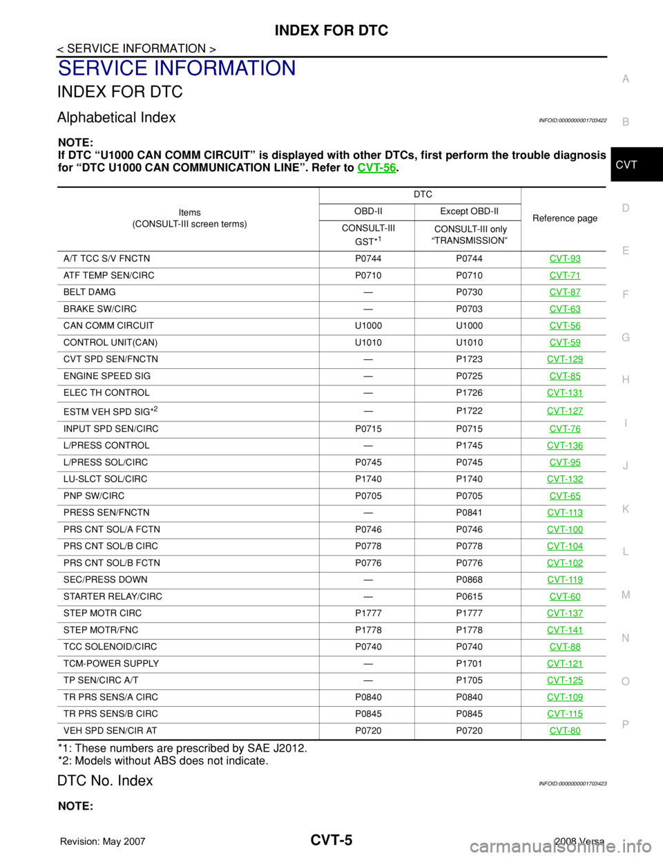
Alphabetical IndexINFOID:0000000001703422
NOTE:
If DTC “U1000 CAN COMM CIRCUIT” is displayed with other DTCs, first perform the trouble diagnosis
for “DTC U1000 CAN COMMUNICATION LINE”. Refer to CVT-56
.
*1: These numbers are prescribed by SAE J2012.
*2: Models without ABS does not indicate.
DTC No. IndexINFOID:0000000001703423
NOTE:
Items
(CONSULT-III screen terms) DTC
Reference page OBD-II Except OBD-II
CONSULT-III
GST*
1 CONSULT-III only
“TRANSMISSION”
A/T TCC S/V FNCTN P0744 P0744 CVT-93
ATF TEMP SEN/CIRC P0710 P0710CVT-71
BELT DAMG — P0730CVT-87
BRAKE SW/CIRC — P0703CVT-63
CAN COMM CIRCUIT U1000 U1000CVT-56
CONTROL UNIT(CAN) U1010 U1010CVT-59
CVT SPD SEN/FNCTN — P1723CVT-129
ENGINE SPEED SIG — P0725CVT-85
ELEC TH CONTROL — P1726CVT-131
ESTM VEH SPD SIG*2— P1722CVT-127
INPUT SPD SEN/CIRC P0715 P0715CVT-76
L/PRESS CONTROL — P1745CVT-136
L/PRESS SOL/CIRC P0745 P0745CVT-95
LU-SLCT SOL/CIRC P1740 P1740CVT-132
PNP SW/CIRC P0705 P0705CVT-65
PRESS SEN/FNCTN — P0841CVT-113
PRS CNT SOL/A FCTN P0746 P0746CVT-100
PRS CNT SOL/B CIRC P0778 P0778CVT-104
PRS CNT SOL/B FCTN P0776 P0776CVT-102
SEC/PRESS DOWN — P0868CVT-119
STARTER RELAY/CIRC — P0615CVT-60
STEP MOTR CIRC P1777 P1777CVT-137
STEP MOTR/FNC P1778 P1778CVT-141
TCC SOLENOID/CIRC P0740 P0740CVT-88
TCM-POWER SUPPLY — P1701CVT-121
TP SEN/CIRC A/T — P1705CVT-125
TR PRS SENS/A CIRC P0840 P0840CVT-109
TR PRS SENS/B CIRC P0845 P0845CVT-115
VEH SPD SEN/CIR AT P0720 P0720CVT-80