2008 NISSAN LATIO door lock
[x] Cancel search: door lockPage 2369 of 2771
TROUBLE DIAGNOSIS
MTC-31
< SERVICE INFORMATION >
C
D
E
F
G
H
I
K
L
MA
B
MTC
N
O
P
1. Turn blower control dial clockwise to "1" position. Blower should operate on low speed.
2. Turn blower control dial clockwise to "2" position, and continue checking blower speed until all speeds are
checked.
3. Leave blower on Maximum speed.
If NG, go to trouble diagnosis procedure for MTC-33, "
Front Blower Motor Circuit".
If OK, continue the check.
CHECKING DISCHARGE AIR
1. Turn mode door control dial to each position.
2. Confirm that discharge air comes out according to the air distribution table. Refer to MTC-20, "
Discharge
Air Flow".
If NG, go to trouble diagnosis procedure for MTC-31, "
Mode Door".
If OK, continue the check.
CHECKING RECIRCULATION
1. Set intake door lever to REC position.
2. Operate intake door lever to FRE position.
3. Listen for intake door position change (you should hear blower sound change slightly).
If NG, go to trouble diagnosis procedure for MTC-33, "
Intake Door".
If OK, continue the check.
CHECKING TEMPERATURE DECREASE
1. Turn temperature control dial counterclockwise to full cold position.
2. Check for cold air at discharge air outlets.
If NG, go to trouble diagnosis procedure for MTC-45, "
Insufficient Cooling".
If OK, continue the check.
CHECKING TEMPERATURE INCREASE
1. Turn temperature control dial clockwise to full hot position.
2. Check for hot air at discharge air outlets.
If NG, go to trouble diagnosis procedure for MTC-52, "
Insufficient Heating".
If OK, continue the check.
CHECKING A/C SWITCH (IF EQUIPPED)
1. Turn fan control dial to the desired (1 to 4 speed) position.
2. Press A/C switch.
3. A/C switch indicator will turn ON.
• Confirm that the compressor clutch engages (sound or visual inspection).
If NG, go to trouble diagnosis procedure for MTC-37, "
Magnet Clutch Circuit (If Equipped)".
If OK, continue the check.
CHECKING DEFROST A/C SWITCH (IF EQUIPPED)
1. Turn fan control dial to the desired (1 to 4 speed) position.
2. Turn mode dial to ( ) DEF.
3. Confirm that the compressor clutch engages (sound or visual inspection) and the A/C switch indicator illu-
minates.
If NG, go to trouble diagnosis procedure for MTC-37, "
Magnet Clutch Circuit (If Equipped)".
If all operational checks are OK (symptom cannot be duplicated), go to MTC-22, "
How to Perform Trouble
Diagnosis for Quick and Accurate Repair" and perform tests as outlined. If symptom appears, refer to MTC-22,
"How to Perform Trouble Diagnosis for Quick and Accurate Repair" and perform applicable trouble diagnosis
procedures.
Mode DoorINFOID:0000000001704301
SYMPTOM: Air outlet does not change.
INSPECTION FLOW
Page 2370 of 2771
MTC-32
< SERVICE INFORMATION >
TROUBLE DIAGNOSIS
1.CONFIRM SYMPTOM BY PERFORMING OPERATIONAL CHECK - DISCHARGE AIR
1. Rotate the mode door control dial to each position.
2. Confirm that discharge air comes out according to the air distribution table. Refer to MTC-20, "
Discharge
Air Flow".
NOTE:
Confirm that the compressor clutch (with A/C) is engaged (visual inspection) when DEF ( ) or D/F ( )
is selected.
Can a symptom be duplicated?
YES >> GO TO 3.
NO >> GO TO 2.
2.PERFORM COMPLETE OPERATIONAL CHECK
Perform a complete operational check and check for any symptoms. Refer to MTC-30, "
Operational Check".
Can a symptom be duplicated?
YES >> Refer to MTC-22, "How to Perform Trouble Diagnosis for Quick and Accurate Repair".
NO >> System OK.
3.CHECK FOR SERVICE BULLETINS
Check for any service bulletins.
>> GO TO 4.
4.CHECK MODE DOOR CONTROL CABLE
Check and verify mode door mechanism for smooth operation in each mode.
OK or NG
OK >> If the symptom still exists, perform a complete operational check and check for other symptoms.
Refer to MTC-30, "
Operational Check". If other symptoms exist, refer to MTC-22, "How to Perform
Trouble Diagnosis for Quick and Accurate Repair" .
NG >> Repair or adjust mode door control cable. Refer to MTC-65, "
Mode Door Cable Adjustment".
Air Mix DoorINFOID:0000000001704302
SYMPTOM: Air mix door does not change.
INSPECTION FLOW
1.CONFIRM SYMPTOM BY PERFORMING OPERATIONAL CHECK - TEMPERATURE INCREASE
1. Turn the temperature control dial clockwise until maximum heat.
2. Check for hot air at discharge air outlets.
>> GO TO 2.
2.CONFIRM SYMPTOM BY PERFORMING OPERATIONAL CHECK - TEMPERATURE DECREASE
1. Turn the temperature control dial counterclockwise until maximum cold.
2. Check for cold air at discharge air outlets.
Can a symptom be duplicated?
YES >> GO TO 4.
NO >> GO TO 3.
3.PERFORM COMPLETE OPERATIONAL CHECK
Perform a complete operational check and check for any symptoms. Refer to MTC-30, "
Operational Check".
Can a symptom be duplicated?
YES >> Refer to MTC-22, "How to Perform Trouble Diagnosis for Quick and Accurate Repair".
NO >> System OK.
4.CHECK FOR SERVICE BULLETINS
Check for any service bulletins.
Page 2383 of 2771
TROUBLE DIAGNOSIS
MTC-45
< SERVICE INFORMATION >
C
D
E
F
G
H
I
K
L
MA
B
MTC
N
O
P
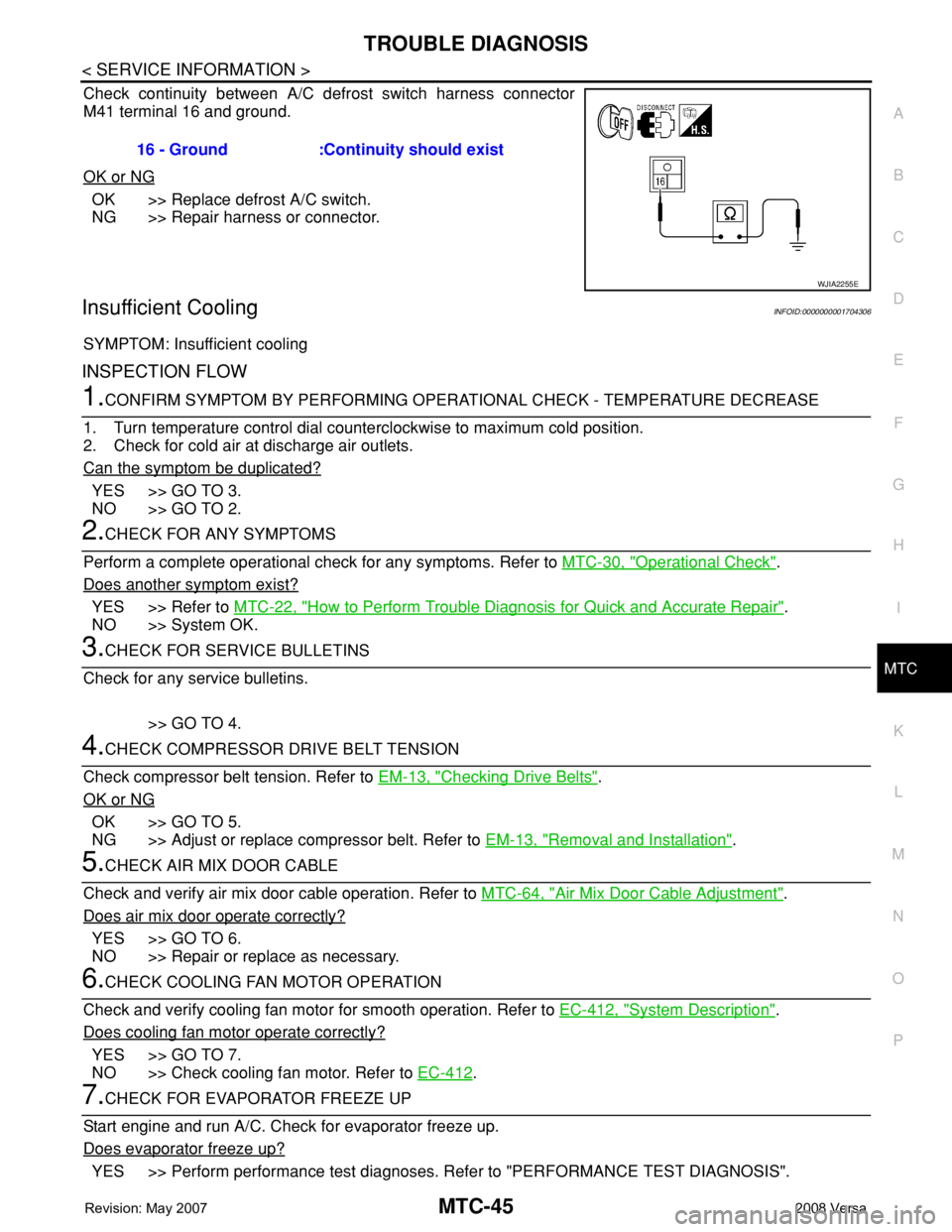
Check continuity between A/C defrost switch harness connector
M41 terminal 16 and ground.
OK or NG
OK >> Replace defrost A/C switch.
NG >> Repair harness or connector.
Insufficient CoolingINFOID:0000000001704306
SYMPTOM: Insufficient cooling
INSPECTION FLOW
1.CONFIRM SYMPTOM BY PERFORMING OPERATIONAL CHECK - TEMPERATURE DECREASE
1. Turn temperature control dial counterclockwise to maximum cold position.
2. Check for cold air at discharge air outlets.
Can the symptom be duplicated?
YES >> GO TO 3.
NO >> GO TO 2.
2.CHECK FOR ANY SYMPTOMS
Perform a complete operational check for any symptoms. Refer to MTC-30, "
Operational Check".
Does another symptom exist?
YES >> Refer to MTC-22, "How to Perform Trouble Diagnosis for Quick and Accurate Repair".
NO >> System OK.
3.CHECK FOR SERVICE BULLETINS
Check for any service bulletins.
>> GO TO 4.
4.CHECK COMPRESSOR DRIVE BELT TENSION
Check compressor belt tension. Refer to EM-13, "
Checking Drive Belts".
OK or NG
OK >> GO TO 5.
NG >> Adjust or replace compressor belt. Refer to EM-13, "
Removal and Installation".
5.CHECK AIR MIX DOOR CABLE
Check and verify air mix door cable operation. Refer to MTC-64, "
Air Mix Door Cable Adjustment".
Does air mix door operate correctly?
YES >> GO TO 6.
NO >> Repair or replace as necessary.
6.CHECK COOLING FAN MOTOR OPERATION
Check and verify cooling fan motor for smooth operation. Refer to EC-412, "
System Description".
Does cooling fan motor operate correctly?
YES >> GO TO 7.
NO >> Check cooling fan motor. Refer to EC-412
.
7.CHECK FOR EVAPORATOR FREEZE UP
Start engine and run A/C. Check for evaporator freeze up.
Does evaporator freeze up?
YES >> Perform performance test diagnoses. Refer to "PERFORMANCE TEST DIAGNOSIS". 16 - Ground :Continuity should exist
WJIA2255E
Page 2390 of 2771
MTC-52
< SERVICE INFORMATION >
TROUBLE DIAGNOSIS
Insufficient Heating
INFOID:0000000001704307
SYMPTOM: Insufficient heating
INSPECTION FLOW
1.CONFIRM SYMPTOM BY PERFORMING OPERATIONAL CHECK - TEMPERATURE DECREASE
1. Turn temperature control dial clockwise to maximum heat position.
2. Check for hot air at discharge air outlets.
Can the symptom be duplicated?
YES >> GO TO 3.
NO >> GO TO 2.
2.CHECK FOR ANY SYMPTOMS
Perform a complete operational check for any symptoms. Refer to MTC-30, "
Operational Check" .
Does another symptom exist?
YES >> Refer to MTC-22, "How to Perform Trouble Diagnosis for Quick and Accurate Repair" .
NO >> System OK.
3.CHECK FOR SERVICE BULLETINS
Check for any service bulletins.
>> GO TO 4.
4.CHECK COOLANT SYSTEM
1. Check engine coolant level. Refer to CO-8
.
2. Check hoses for leaks or kinks.
3. Check Radiator cap. Refer to CO-13, "
Checking Radiator Cap" .
OK or NG
OK >> GO TO 5.
NG >> Repair/replace as necessary.
5.CHECK AIR MIX DOOR CABLE
Check air mix door cable operation. Refer to MTC-64, "
Air Mix Door Cable Adjustment" .
OK or NG
YES >> GO TO 6.
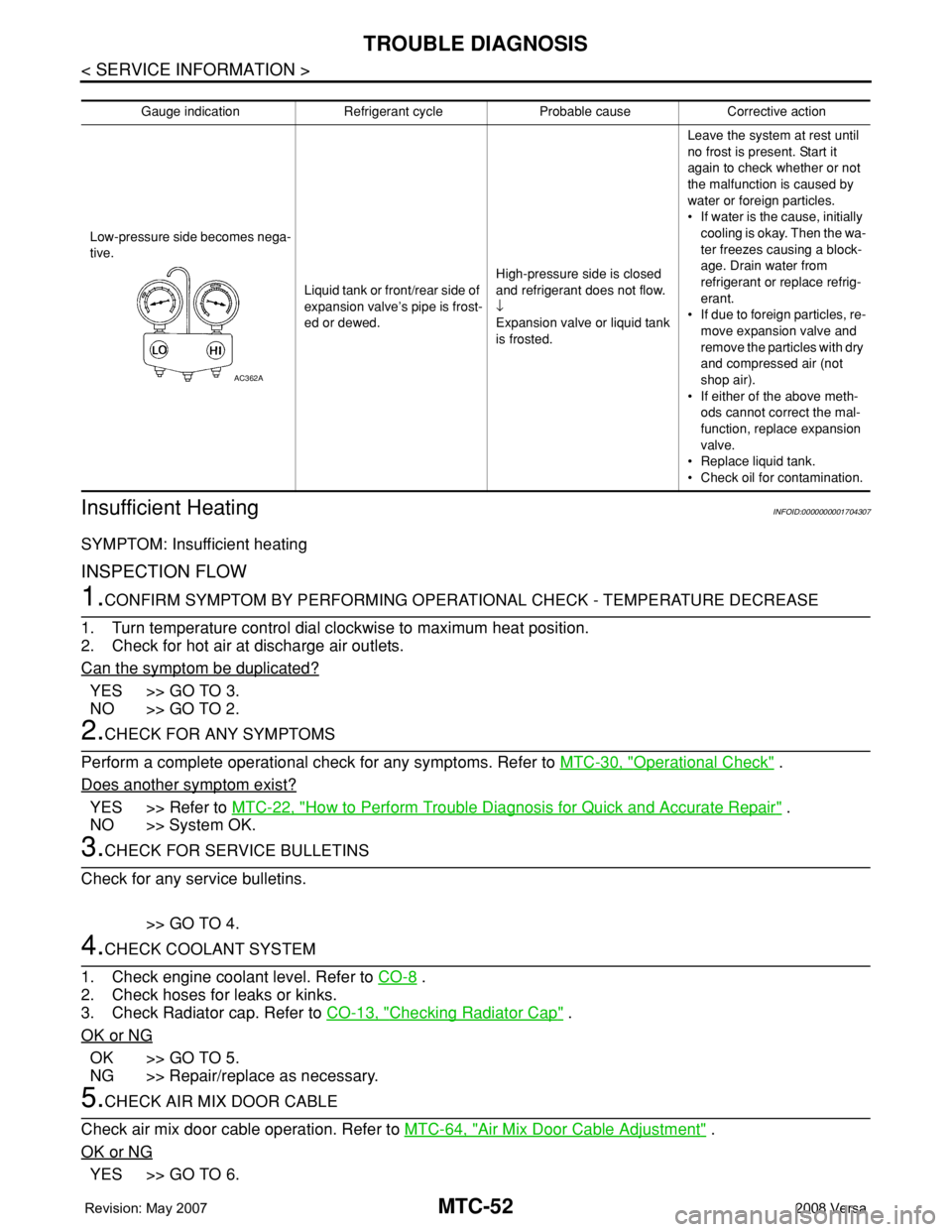
Gauge indication Refrigerant cycle Probable cause Corrective action
Low-pressure side becomes nega-
tive.
Liquid tank or front/rear side of
expansion valve’s pipe is frost-
ed or dewed.High-pressure side is closed
and refrigerant does not flow.
↓
Expansion valve or liquid tank
is frosted.Leave the system at rest until
no frost is present. Start it
again to check whether or not
the malfunction is caused by
water or foreign particles.
• If water is the cause, initially
cooling is okay. Then the wa-
ter freezes causing a block-
age. Drain water from
refrigerant or replace refrig-
erant.
• If due to foreign particles, re-
move expansion valve and
remove the particles with dry
and compressed air (not
shop air).
• If either of the above meth-
ods cannot correct the mal-
function, replace expansion
valve.
• Replace liquid tank.
• Check oil for contamination.
AC362A
Page 2406 of 2771
MTC-68
< SERVICE INFORMATION >
AIR CONDITIONER FILTER
AIR CONDITIONER FILTER
Removal and InstallationINFOID:0000000001704320
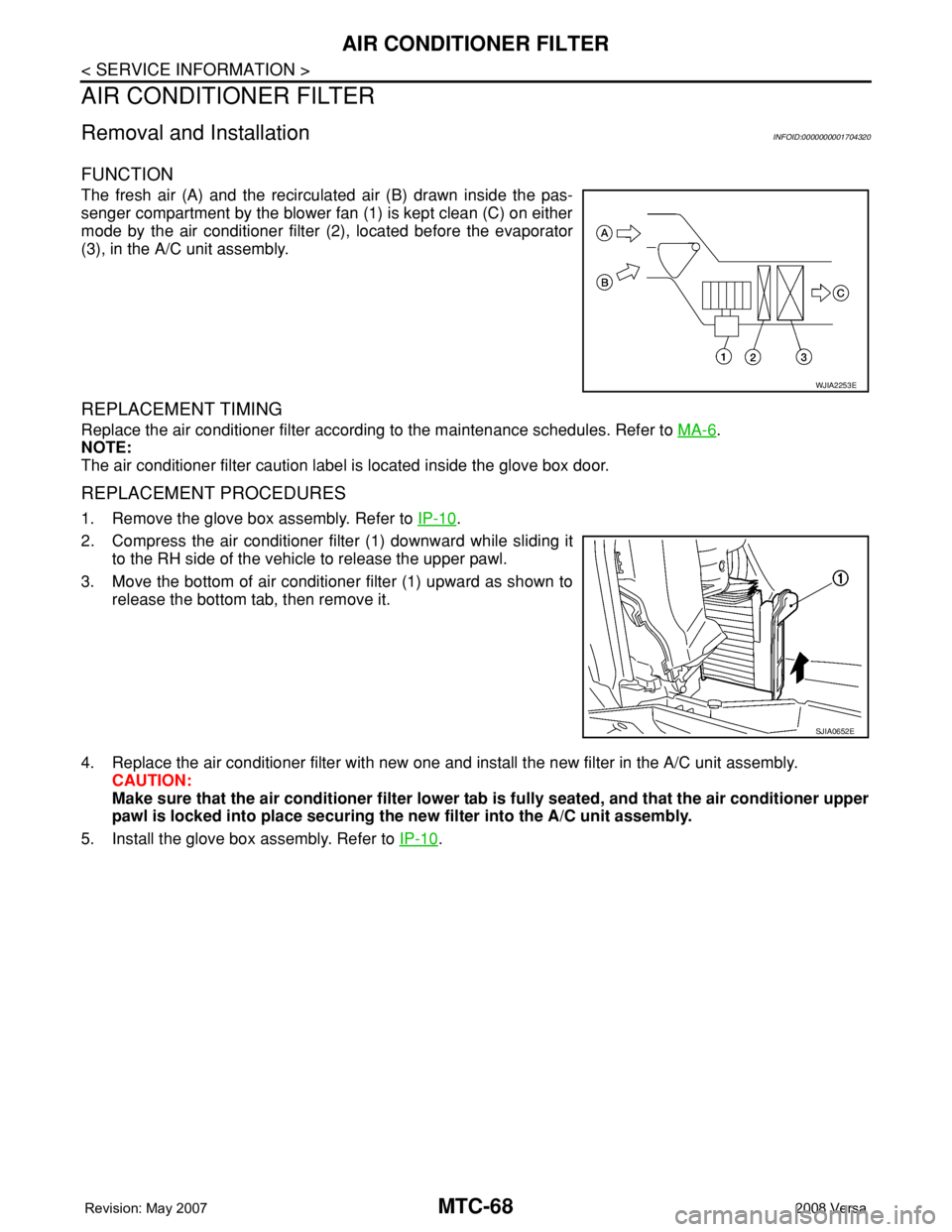
FUNCTION
The fresh air (A) and the recirculated air (B) drawn inside the pas-
senger compartment by the blower fan (1) is kept clean (C) on either
mode by the air conditioner filter (2), located before the evaporator
(3), in the A/C unit assembly.
REPLACEMENT TIMING
Replace the air conditioner filter according to the maintenance schedules. Refer to MA-6.
NOTE:
The air conditioner filter caution label is located inside the glove box door.
REPLACEMENT PROCEDURES
1. Remove the glove box assembly. Refer to IP-10.
2. Compress the air conditioner filter (1) downward while sliding it
to the RH side of the vehicle to release the upper pawl.
3. Move the bottom of air conditioner filter (1) upward as shown to
release the bottom tab, then remove it.
4. Replace the air conditioner filter with new one and install the new filter in the A/C unit assembly.
CAUTION:
Make sure that the air conditioner filter lower tab is fully seated, and that the air conditioner upper
pawl is locked into place securing the new filter into the A/C unit assembly.
5. Install the glove box assembly. Refer to IP-10
.
WJIA2253E
SJIA0652E
Page 2457 of 2771

PG-24
< SERVICE INFORMATION >
IPDM E/R (INTELLIGENT POWER DISTRIBUTION MODULE ENGINE ROOM)
24 Y Cooling fan relay-3 Output —Conditions correct for cooling
fan high operationBattery voltage
Conditions not correct for
cooling fan high operation0V
26 OTail lamp relay (park-
ing lamps)Output — Lighting switch in 2nd position Battery voltage
27 BRTail lamp relay (park-
ing lamps)Output — Lighting switch in 2nd position Battery voltage
28 GRTail lamp relay (park-
ing lamps)Output — Lighting switch in 2nd position Battery voltage
29 PTail lamp relay (park-
ing lamps)Output — Lighting switch in 2nd position Battery voltage
30
(A/T
only)R Fuse 54 Output —Ignition switch ON or START Battery voltage
Ignition switch OFF or ACC 0V
31 O Fuse 55 Output —Ignition switch ON or START Battery voltage
Ignition switch OFF or ACC 0V
32 LWiper high speed sig-
nalOutputON or
STARTWiper switchOFF, LO, INT 0V
HI Battery voltage
33 YWiper low speed sig-
nalOutputON or
STARTWiper switchOFF 0V
LO or INT Battery voltage
35 BRStarter relay (inhibit
switch)InputON or
STARTSelector lever in "P" or "N"
(CVT or A/T) or clutch pedal
depressed (M/T)Battery voltage
Selector lever any other posi-
tion (CVT or A/T) or clutch
pedal released (M/T)0V
36 BR Fuel pump relay Output —Ignition switch ON or START Battery voltage
Ignition switch OFF or ACC 0V
37 G Oil pressure switch InputON or
STARTEngine running and oil pres-
sure within specificationBattery voltage
Engine not running or oil pres-
sure below specification0V
38 R Wiper auto stop signal InputON or
STARTWipers not in park position Battery voltage
Wipers in park position 0V
39 B Ground Input — — 0V
40 P CAN-L — ON — —
41 L CAN-H — ON — —
45 R Horn relay control Input —Horn switch PUSHED, alarm
switch activated or door lock/
unlock is confirmed when op-
erating lock system via the
keyfob0V
Horn switch released, alarm
not active, keyfob not activeBattery voltage
46 YThrottle control motor
relay controlInput —Ignition switch ON or START 0V
Ignition switch OFF or ACC Battery voltage
47 GRFuel pump relay con-
trolInput —
Ignition switch ON or START 0V
Ignition switch OFF or ACC Battery voltage Te r m i n a lWire
colorSignal nameSignal
input/
outputMeasuring condition
Reference value
(Approx.) Ignition
switchOperation or condition
Page 2472 of 2771

HARNESS
PG-39
< SERVICE INFORMATION >
C
D
E
F
G
H
I
J
L
MA
B
PG
N
O
P
C2 M6 W/4 : Steering lock solenoid E2 M52 W/40 : Intelligent key unit
B3 M7 W/16 : Door mirror remote control switch B2 M53 W/16 : EPS control unit
A3 M8 W/16 : To D2 B3 M54 B/2 : EPS control unit
A3 M9 W/16 : To D1 C3 M55† W/4: Hazard switch (hatchback early
production)
E2 M10 GR/2 : Instrument panel antenna D2 M55†† W/4: Hazard switch (hatchback late production
or sedan)
G3 M11 W/4 : To B106 B2 M57 — : Body ground
G4 M12 W/16 : To B101 F2 M59 W/2 : Glove box lamp
G3 M13 W/24 : To B102 C1 M60 L/2 : EPS control unit
G3 M14 W/24 : To B120 F1 M61 — : Body ground
B4 M15 W/16 : To B23 E2 M62 W/2 : Front blower motor
B4 M16 W/24 : To B24 C1 M63 W/4 : Torque sensor
D5 M17 B/1 : Parking brake switch A2 M69 SMJ : To E7
F2 M18 W/40 : BCM (body control module) B2 M73 GR/6: Key switch and ignition knob switch (With
intelligent key)
F2 M19 W/15 : BCM (body control module) G3 M74 W/12 : To D102
F3 M20 B/15 : BCM (body control module) G3 M75 W/12 : To D101
C2 M21 W/4 : NATS antenna amp. F2 M77 Y/4 : Front passenger air bag module
B3 M22 W/16 : Data link connector A2 M78 B/2 : To E11
E3 M23 W/4 : Remote keyless entry receiver B1 M79 — : Body ground
C1 M24 W/40 : Combination meter D3 M150 W/4 : To M32
C3 M25 /2 : Diode-1 C3 M151 W/4 : Front blower motor resistor
B2 M26 W/6 : Ignition switch
C2 M27 GR/6 : Key switch and key lock solenoid
C2 M28 W/16 : Combination switch
C3 M29 Y/6 : Combination switch (spiral cable)
C3 M30 GR/8 : Combination switch (spiral cable)
E3 M32 W/4 : To M150
D2 M33 B/15 : Front air control
D4 M35 Y/28 : Air bag diagnosis sensor unit
D2 M36† W/3: Front passenger air bag OFF indicator
(hatchback early production)
C3 M36†† W/3: Front passenger air bag OFF indicator
(hatchback late production or sedan)
D4 M38 W/6 : A/T device
D4 M38 W/6 : CVT device (without intelligent key)
D4 M38 W/8 : CVT device (with intelligent key)
B3 M39 W/2 : Tire pressure warning check connector
D2 M41 W/2 : Defrost A/C switch
D3 M42 W/3 : Thermo control amp. (without CVT)
D2 M43 W/20 : Audio unit
Page 2486 of 2771
HARNESS
PG-53
< SERVICE INFORMATION >
C
D
E
F
G
H
I
J
L
MA
B
PG
N
O
P
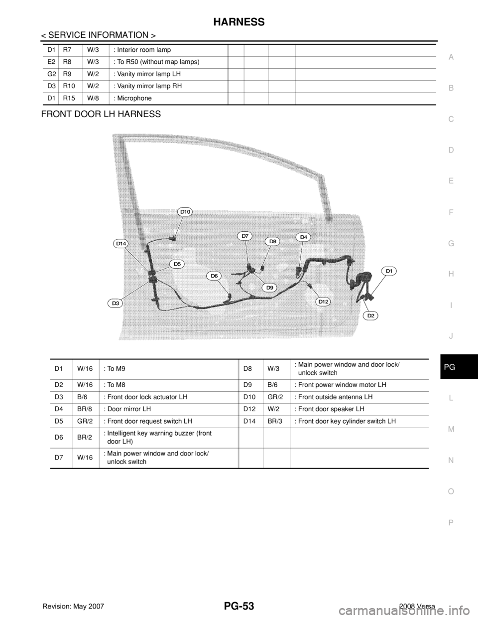
FRONT DOOR LH HARNESS
D1 R7 W/3 : Interior room lamp
E2 R8 W/3 : To R50 (without map lamps)
G2 R9 W/2 : Vanity mirror lamp LH
D3 R10 W/2 : Vanity mirror lamp RH
D1 R15 W/8 : Microphone
D1 W/16 : To M9 D8 W/3: Main power window and door lock/
unlock switch
D2 W/16 : To M8 D9 B/6 : Front power window motor LH
D3 B/6 : Front door lock actuator LH D10 GR/2 : Front outside antenna LH
D4 BR/8 : Door mirror LH D12 W/2 : Front door speaker LH
D5 GR/2 : Front door request switch LH D14 BR/3 : Front door key cylinder switch LH
D6 BR/2: Intelligent key warning buzzer (front
door LH)
D7 W/16: Main power window and door lock/
unlock switch