Page 2395 of 2771
THERMO CONTROL AMPLIFIER
MTC-57
< SERVICE INFORMATION >
C
D
E
F
G
H
I
K
L
MA
B
MTC
N
O
P
THERMO CONTROL AMPLIFIER
Removal and InstallationINFOID:0000000001704311
NOTE:
Only TYPE 1 systems are equipped with a thermo control amplifier.
REMOVAL
1. Remove evaporator. Refer to MTC-83, "Removal and Installation of Evaporator" .
CAUTION:
Cap or wrap the joint of the pipe with suitable material such as vinyl tape to avoid the entry of air.
2. Remove thermo control amp. (1) from evaporator (2).
INSTALLATION
Installation is in the reverse order of removal.
CAUTION:
• Replace O-rings for A/C piping with new ones, and apply compressor oil when installing.
• Mark the mounting position of thermo control amp.
• When recharging refrigerant, check for leaks.
ZJIA0798J
Page 2397 of 2771
A/C UNIT ASSEMBLY
MTC-59
< SERVICE INFORMATION >
C
D
E
F
G
H
I
K
L
MA
B
MTC
N
O
P
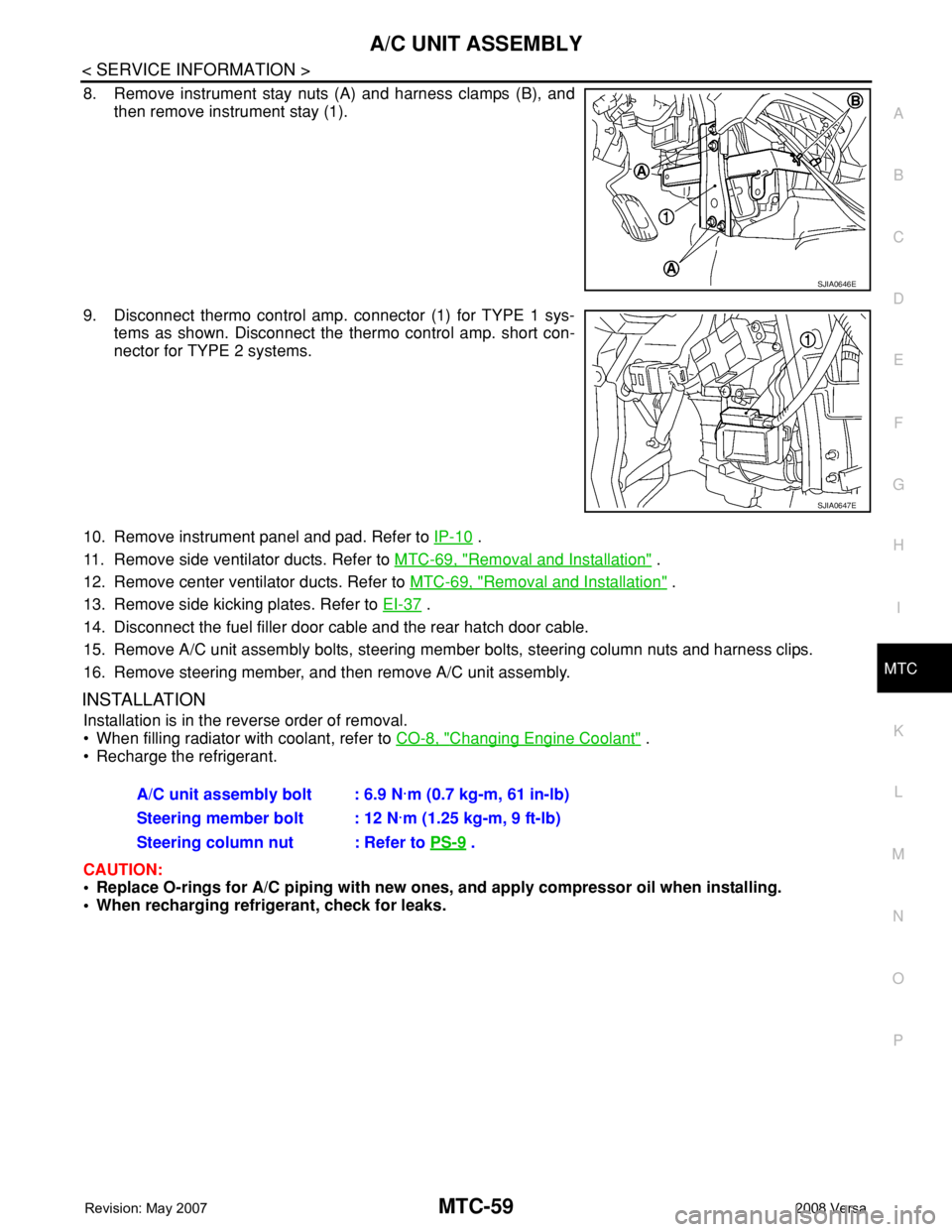
8. Remove instrument stay nuts (A) and harness clamps (B), and
then remove instrument stay (1).
9. Disconnect thermo control amp. connector (1) for TYPE 1 sys-
tems as shown. Disconnect the thermo control amp. short con-
nector for TYPE 2 systems.
10. Remove instrument panel and pad. Refer to IP-10
.
11. Remove side ventilator ducts. Refer to MTC-69, "
Removal and Installation" .
12. Remove center ventilator ducts. Refer to MTC-69, "
Removal and Installation" .
13. Remove side kicking plates. Refer to EI-37
.
14. Disconnect the fuel filler door cable and the rear hatch door cable.
15. Remove A/C unit assembly bolts, steering member bolts, steering column nuts and harness clips.
16. Remove steering member, and then remove A/C unit assembly.
INSTALLATION
Installation is in the reverse order of removal.
• When filling radiator with coolant, refer to CO-8, "
Changing Engine Coolant" .
• Recharge the refrigerant.
CAUTION:
• Replace O-rings for A/C piping with new ones, and apply compressor oil when installing.
• When recharging refrigerant, check for leaks.
SJIA0646E
SJIA0647E
A/C unit assembly bolt : 6.9 N·m (0.7 kg-m, 61 in-lb)
Steering member bolt : 12 N·m (1.25 kg-m, 9 ft-lb)
Steering column nut : Refer to PS-9
.
Page 2413 of 2771
REFRIGERANT LINES
MTC-75
< SERVICE INFORMATION >
C
D
E
F
G
H
I
K
L
MA
B
MTC
N
O
P
7. Manifold gauge set (J-39183) A. Preferred (best) method B. Alternative method
C. For charging
*1MTC-16, "
Maintenance of Oil Quanti-
ty in Compressor"
*2MTC-84, "Checking of Refrigerant
Leaks"
*3MTC-85, "Electronic Refrigerant
Leak Detector"
*4MTC-45, "Insufficient Cooling"
WJIA1923E
Page 2417 of 2771
REFRIGERANT LINES
MTC-79
< SERVICE INFORMATION >
C
D
E
F
G
H
I
K
L
MA
B
MTC
N
O
P
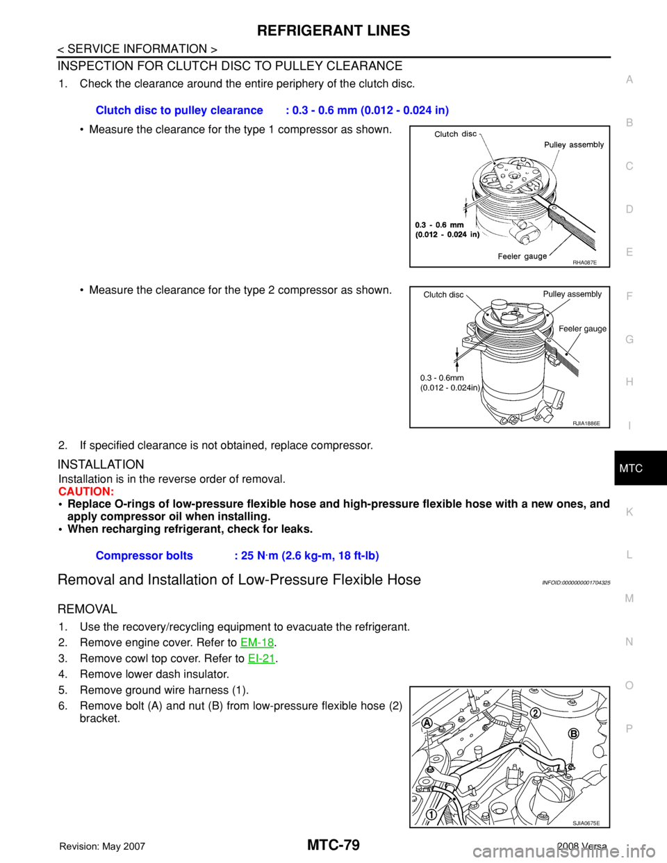
INSPECTION FOR CLUTCH DISC TO PULLEY CLEARANCE
1. Check the clearance around the entire periphery of the clutch disc.
• Measure the clearance for the type 1 compressor as shown.
• Measure the clearance for the type 2 compressor as shown.
2. If specified clearance is not obtained, replace compressor.
INSTALLATION
Installation is in the reverse order of removal.
CAUTION:
• Replace O-rings of low-pressure flexible hose and high-pressure flexible hose with a new ones, and
apply compressor oil when installing.
• When recharging refrigerant, check for leaks.
Removal and Installation of Low-Pressure Flexible HoseINFOID:0000000001704325
REMOVAL
1. Use the recovery/recycling equipment to evacuate the refrigerant.
2. Remove engine cover. Refer to EM-18
.
3. Remove cowl top cover. Refer to EI-21
.
4. Remove lower dash insulator.
5. Remove ground wire harness (1).
6. Remove bolt (A) and nut (B) from low-pressure flexible hose (2)
bracket.Clutch disc to pulley clearance : 0.3 - 0.6 mm (0.012 - 0.024 in)
RHA087E
RJIA1886E
Compressor bolts : 25 N·m (2.6 kg-m, 18 ft-lb)
SJIA0675E
Page 2418 of 2771
MTC-80
< SERVICE INFORMATION >
REFRIGERANT LINES
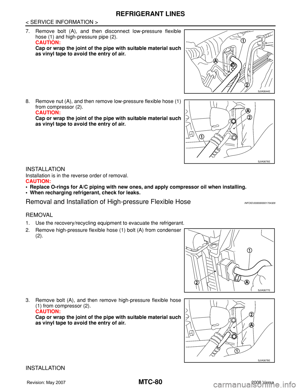
7. Remove bolt (A), and then disconnect low-pressure flexible
hose (1) and high-pressure pipe (2).
CAUTION:
Cap or wrap the joint of the pipe with suitable material such
as vinyl tape to avoid the entry of air.
8. Remove nut (A), and then remove low-pressure flexible hose (1)
from compressor (2).
CAUTION:
Cap or wrap the joint of the pipe with suitable material such
as vinyl tape to avoid the entry of air.
INSTALLATION
Installation is in the reverse order of removal.
CAUTION:
• Replace O-rings for A/C piping with new ones, and apply compressor oil when installing.
• When recharging refrigerant, check for leaks.
Removal and Installation of High-pressure Flexible HoseINFOID:0000000001704326
REMOVAL
1. Use the recovery/recycling equipment to evacuate the refrigerant.
2. Remove high-pressure flexible hose (1) bolt (A) from condenser
(2).
3. Remove bolt (A), and then remove high-pressure flexible hose
(1) from compressor (2).
CAUTION:
Cap or wrap the joint of the pipe with suitable material such
as vinyl tape to avoid the entry of air.
INSTALLATION
SJIA0644E
SJIA0676E
SJIA0677E
SJIA0678E
Page 2419 of 2771
REFRIGERANT LINES
MTC-81
< SERVICE INFORMATION >
C
D
E
F
G
H
I
K
L
MA
B
MTC
N
O
P
Installation is in the reverse order of removal.
CAUTION:
• Replace O-rings of high-pressure flexible hose with a new ones, and apply compressor oil when
installing.
• When recharging refrigerant, check for leaks.
Removal and Installation of High-pressure PipeINFOID:0000000001704327
REMOVAL
1. Remove low-pressure flexible hose. Refer to MTC-79, "Removal and Installation of Low-Pressure Flexible
Hose".
2. Remove high-pressure pipe from the clips.
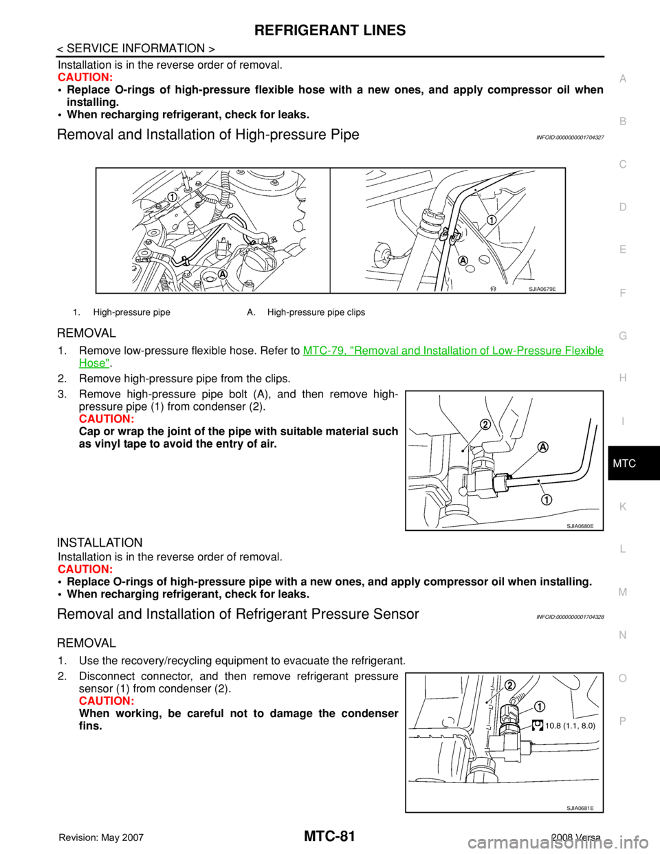
3. Remove high-pressure pipe bolt (A), and then remove high-
pressure pipe (1) from condenser (2).
CAUTION:
Cap or wrap the joint of the pipe with suitable material such
as vinyl tape to avoid the entry of air.
INSTALLATION
Installation is in the reverse order of removal.
CAUTION:
• Replace O-rings of high-pressure pipe with a new ones, and apply compressor oil when installing.
• When recharging refrigerant, check for leaks.
Removal and Installation of Refrigerant Pressure SensorINFOID:0000000001704328
REMOVAL
1. Use the recovery/recycling equipment to evacuate the refrigerant.
2. Disconnect connector, and then remove refrigerant pressure
sensor (1) from condenser (2).
CAUTION:
When working, be careful not to damage the condenser
fins.
1. High-pressure pipe A. High-pressure pipe clips
SJIA0679E
SJIA0680E
SJIA0681E
Page 2420 of 2771
MTC-82
< SERVICE INFORMATION >
REFRIGERANT LINES
INSTALLATION
Installation is in the reverse order of removal.
CAUTION:
• Replace O-rings of refrigerant pressure sensor with a new one, and apply compressor oil when
installing.
• When recharging refrigerant, check for leaks.
Removal and Installation of CondenserINFOID:0000000001704329
REMOVAL
1. Remove the three upper headlamp bolts to reposition the headlamps out of the way
2. Remove the radiator core support upper. Refer to BL-19
.
3. Remove high-pressure flexible hose and high-pressure pipe from condenser. Refer to MTC-80, "
Removal
and Installation of High-pressure Flexible Hose" and MTC-81, "Removal and Installation of High-pres-
sure Pipe" .
CAUTION:
Cap or wrap the joint of the pipe with suitable material such as vinyl tape to avoid the entry of air.
4. Disconnect refrigerant pressure sensor connector.
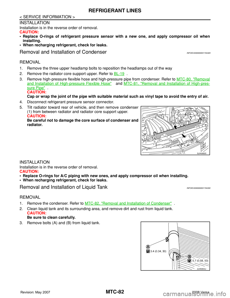
5. Tilt radiator toward rear of vehicle, and then remove condenser
(1) from between radiator and radiator core support upper.
CAUTION:
Be careful not to damage the core surface of condenser and
radiator.
INSTALLATION
Installation is in the reverse order of removal.
CAUTION:
• Replace O-rings for A/C piping with new ones, and apply compressor oil when installing.
• When recharging refrigerant, check for leaks.
Removal and Installation of Liquid TankINFOID:0000000001704330
REMOVAL
1. Remove the condenser. Refer to MTC-82, "Removal and Installation of Condenser" .
2. Clean liquid tank and its surrounding area, and remove dirt and rust from liquid tank.
CAUTION:
Be sure to clean carefully.
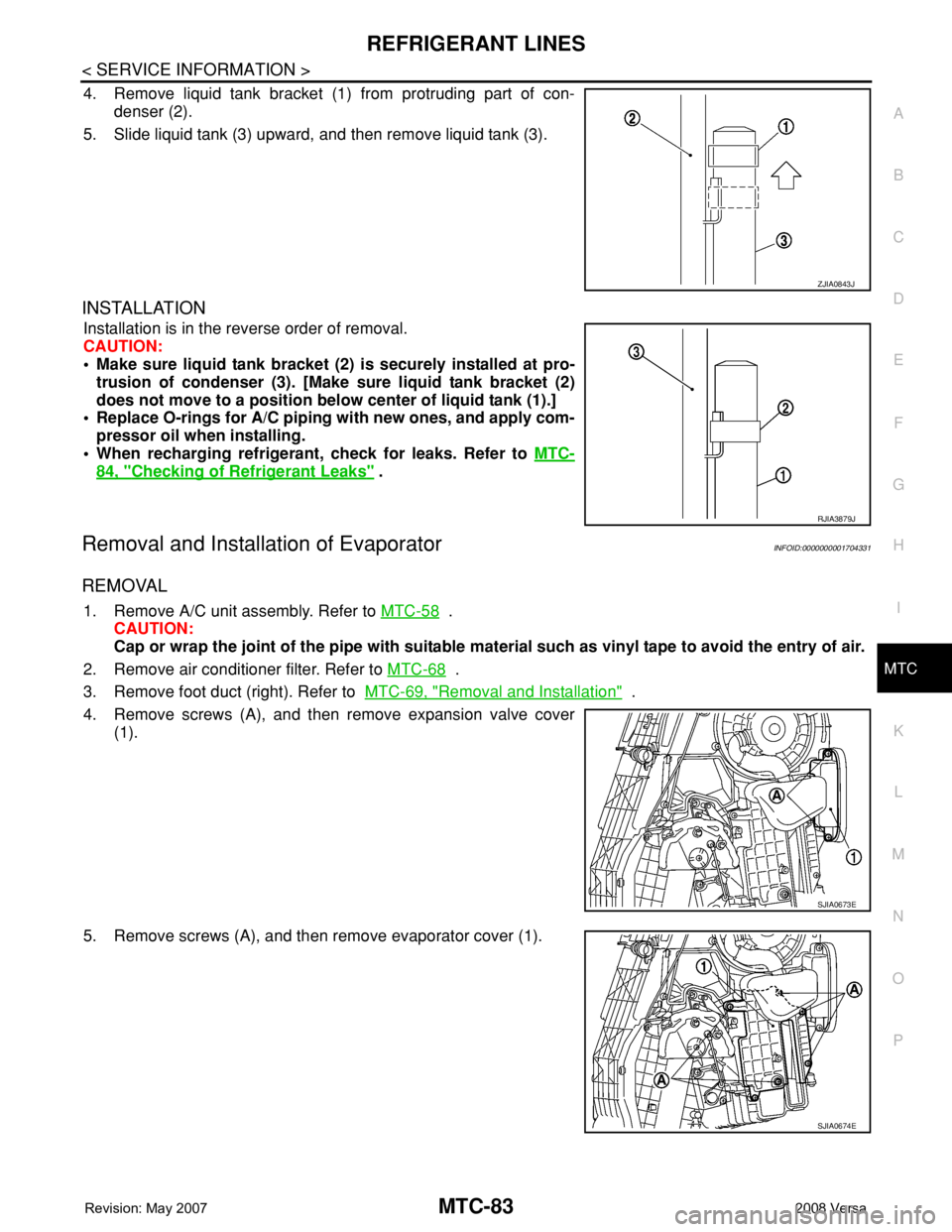
3. Remove bolts (A) and (B) from liquid tank.
SJIA0682E
ZJIA0842J
Page 2421 of 2771
REFRIGERANT LINES
MTC-83
< SERVICE INFORMATION >
C
D
E
F
G
H
I
K
L
MA
B
MTC
N
O
P
4. Remove liquid tank bracket (1) from protruding part of con-
denser (2).
5. Slide liquid tank (3) upward, and then remove liquid tank (3).
INSTALLATION
Installation is in the reverse order of removal.
CAUTION:
• Make sure liquid tank bracket (2) is securely installed at pro-
trusion of condenser (3). [Make sure liquid tank bracket (2)
does not move to a position below center of liquid tank (1).]
• Replace O-rings for A/C piping with new ones, and apply com-
pressor oil when installing.
• When recharging refrigerant, check for leaks. Refer to MTC-
84, "Checking of Refrigerant Leaks" .
Removal and Installation of EvaporatorINFOID:0000000001704331
REMOVAL
1. Remove A/C unit assembly. Refer to MTC-58 .
CAUTION:
Cap or wrap the joint of the pipe with suitable material such as vinyl tape to avoid the entry of air.
2. Remove air conditioner filter. Refer to MTC-68
.
3. Remove foot duct (right). Refer to MTC-69, "
Removal and Installation" .
4. Remove screws (A), and then remove expansion valve cover
(1).
5. Remove screws (A), and then remove evaporator cover (1).
ZJIA0843J
RJIA3879J
SJIA0673E
SJIA0674E