Page 1362 of 2771
EC-288
< SERVICE INFORMATION >
DTC P0300 - P0304 MULTIPLE CYLINDER MISFIRE, NO. 1 - 4 CYLINDER MIS-
FIRE
Check compression pressure. Refer to EM-62, "On-Vehicle Service".
OK or NG
OK >> GO TO 10.
NG >> Check pistons, piston rings, valves, valve seats and cylinder head gaskets.
10.CHECK FUEL PRESSURE
1. Install all removed parts.
2. Release fuel pressure to zero. Refer to EC-78, "
Fuel Pressure Check".
3. Install fuel pressure gauge and check fuel pressure. Refer to EC-78, "
Fuel Pressure Check".
OK or NG
OK >> GO TO 12.
NG >> GO TO 11.
11 .DETECT MALFUNCTIONING PART
Check the following.
• Fuel pump and circuit (Refer to EC-526
.)
• Fuel pressure regulator (Refer to EC-78, "
Fuel Pressure Check".)
• Fuel lines (Refer to EM-33
.)
• Fuel filter for clogging
>> Repair or replace.
12.CHECK IGNITION TIMING
Check the following items. Refer to EC-69, "
Basic Inspection".
OK or NG
OK >> GO TO 13.
NG >> Follow the EC-69, "
Basic Inspection".
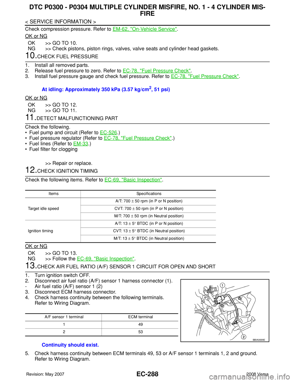
13.CHECK AIR FUEL RATIO (A/F) SENSOR 1 CIRCUIT FOR OPEN AND SHORT
1. Turn ignition switch OFF.
2. Disconnect air fuel ratio (A/F) sensor 1 harness connector (1).
- Air fuel ratio (A/F) sensor 1 (2)
3. Disconnect ECM harness connector.
4. Check harness continuity between the following terminals.
Refer to Wiring Diagram.
5. Check harness continuity between ECM terminals 49, 53 or A/F sensor 1 terminals 1, 2 and ground.
Refer to Wiring Diagram.At idling: Approximately 350 kPa (3.57 kg/cm
2, 51 psi)
Items Specifications
Target idle speedA/T: 700 ± 50 rpm (in P or N position)
CVT: 700 ± 50 rpm (in P or N position)
M/T: 700 ± 50 rpm (in Neutral position)
Ignition timingA/T: 13 ± 5° BTDC (in P or N position)
CVT: 13 ± 5° BTDC (in Neutral position)
M/T: 13 ± 5° BTDC (in Neutral position)
A/F sensor 1 terminal ECM terminal
149
253
Continuity should exist.
BBIA0699E
Page 1366 of 2771
EC-292
< SERVICE INFORMATION >
DTC P0327, P0328 KS
Wiring Diagram
INFOID:0000000001702796
Specification data are reference values and are measured between each terminal and ground.
CAUTION:
Do not use ECM ground terminals when measuring input/output voltage. Doing so may result in dam-
age to the ECM's transistor. Use a ground other than ECM terminals, such as the ground.
BBWA2637E
Page 1367 of 2771
DTC P0327, P0328 KS
EC-293
< SERVICE INFORMATION >
C
D
E
F
G
H
I
J
K
L
MA
EC
N
P O
Diagnosis ProcedureINFOID:0000000001702797
1.CHECK KNOCK SENSOR INPUT SIGNAL CIRCUIT-I
1. Turn ignition switch OFF.
2. Disconnect ECM harness connector.
3. Check resistance between ECM terminal 37 and ground. Refer to Wiring Diagram.
NOTE:
It is necessary to use an ohmmeter which can measure more than 10 MΩ.
4. Also check harness for short to ground and short to power.
OK or NG
OK >> GO TO 4.
NG >> GO TO 2.
2.CHECK KNOCK SENSOR INPUT SIGNAL CIRCUIT-II
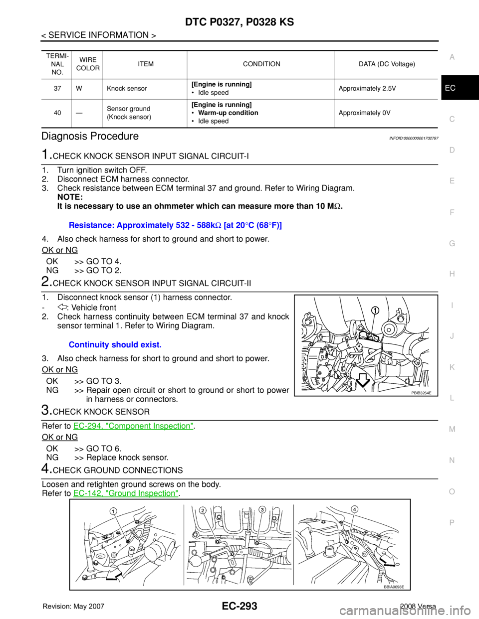
1. Disconnect knock sensor (1) harness connector.
- : Vehicle front
2. Check harness continuity between ECM terminal 37 and knock
sensor terminal 1. Refer to Wiring Diagram.
3. Also check harness for short to ground and short to power.
OK or NG
OK >> GO TO 3.
NG >> Repair open circuit or short to ground or short to power
in harness or connectors.
3.CHECK KNOCK SENSOR
Refer to EC-294, "
Component Inspection".
OK or NG
OK >> GO TO 6.
NG >> Replace knock sensor.
4.CHECK GROUND CONNECTIONS
Loosen and retighten ground screws on the body.
Refer to EC-142, "
Ground Inspection".
TERMI-
NAL
NO.WIRE
COLORITEM CONDITION DATA (DC Voltage)
37 W Knock sensor[Engine is running]
• Idle speedApproximately 2.5V
40 —Sensor ground
(Knock sensor)[Engine is running]
•Warm-up condition
• Idle speedApproximately 0V
Resistance: Approximately 532 - 588kΩ [at 20°C (68°F)]
Continuity should exist.
PBIB3264E
BBIA0698E
Page 1368 of 2771
EC-294
< SERVICE INFORMATION >
DTC P0327, P0328 KS
OK or NG
OK >> GO TO 5.
NG >> Repair or replace ground connections.
5.CHECK KNOCK SENSOR SHIELD CIRCUIT FOR OPEN AND SHORT
1. Reconnect knock sensor harness connector.
2. Check harness continuity between ECM terminal 40 and knock sensor terminal 2.
Refer to Wiring Diagram.
3. Also check harness for short to ground and short to power.
OK or NG
OK >> GO TO 6.
NG >> Repair open circuit or short to ground or short to power in harness or connectors.
6.CHECK INTERMITTENT INCIDENT
Refer to EC-136
.
>>INSPECTION END
Component InspectionINFOID:0000000001702798
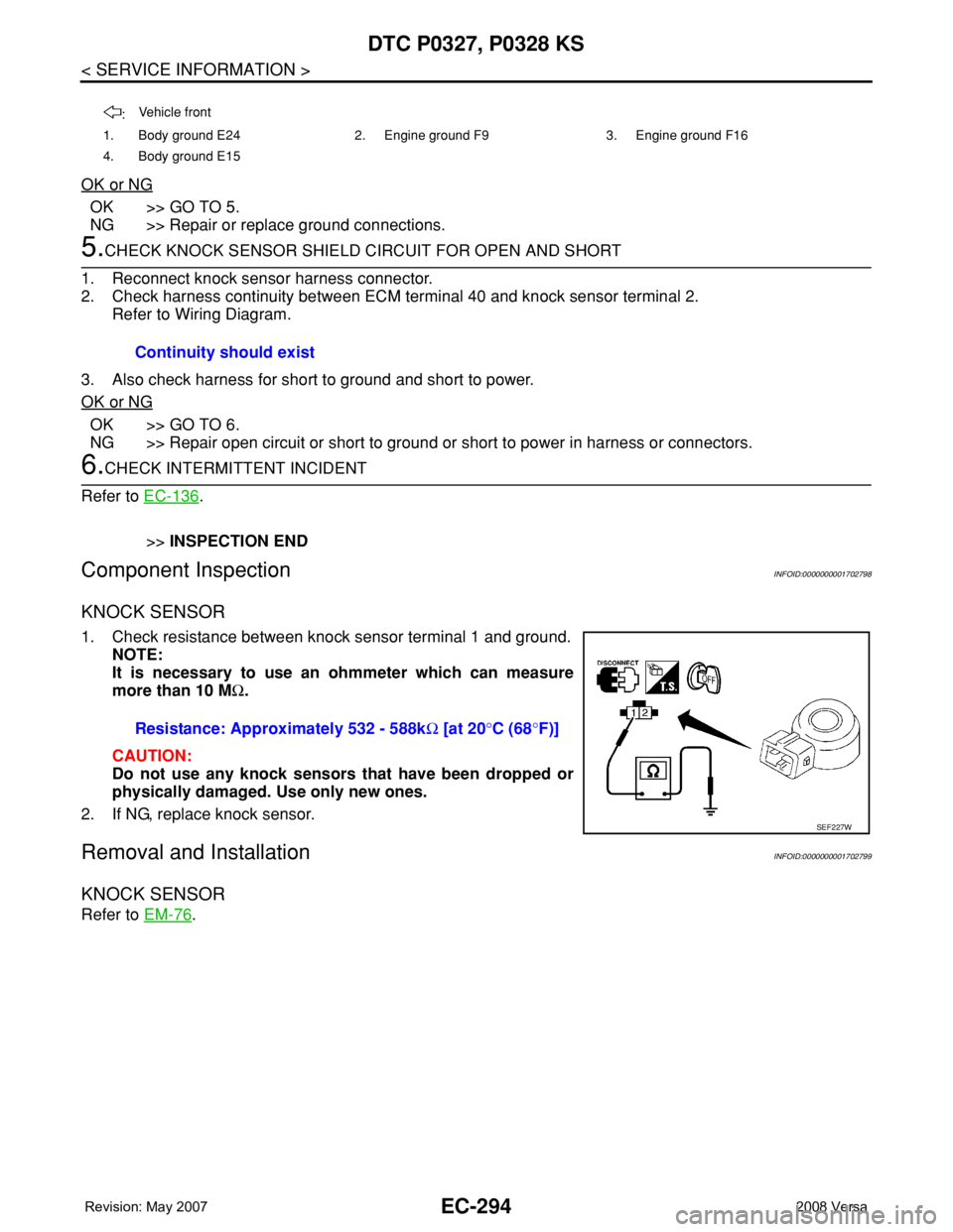
KNOCK SENSOR
1. Check resistance between knock sensor terminal 1 and ground.
NOTE:
It is necessary to use an ohmmeter which can measure
more than 10 MΩ.
CAUTION:
Do not use any knock sensors that have been dropped or
physically damaged. Use only new ones.
2. If NG, replace knock sensor.
Removal and InstallationINFOID:0000000001702799
KNOCK SENSOR
Refer to EM-76.
:Vehicle front
1. Body ground E24 2. Engine ground F9 3. Engine ground F16
4. Body ground E15
Continuity should exist
Resistance: Approximately 532 - 588kΩ [at 20°C (68°F)]
SEF227W
Page 1371 of 2771
DTC P0335 CKP SENSOR (POS)
EC-297
< SERVICE INFORMATION >
C
D
E
F
G
H
I
J
K
L
MA
EC
N
P O
Wiring DiagramINFOID:0000000001702804
Specification data are reference values and are measured between each terminal and ground.
Pulse signal is measured by CONSULT-II.
CAUTION:
BBWA3071E
Page 1373 of 2771
DTC P0335 CKP SENSOR (POS)
EC-299
< SERVICE INFORMATION >
C
D
E
F
G
H
I
J
K
L
MA
EC
N
P O
OK or NG
OK >> GO TO 2.
NG >> Repair or replace ground connections.
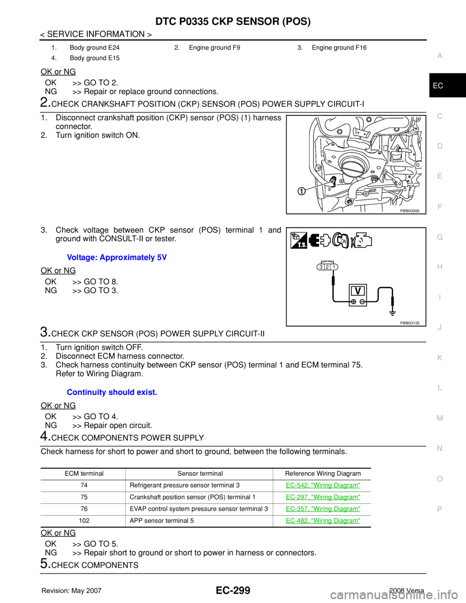
2.CHECK CRANKSHAFT POSITION (CKP) SENSOR (POS) POWER SUPPLY CIRCUIT-I
1. Disconnect crankshaft position (CKP) sensor (POS) (1) harness
connector.
2. Turn ignition switch ON.
3. Check voltage between CKP sensor (POS) terminal 1 and
ground with CONSULT-II or tester.
OK or NG
OK >> GO TO 8.
NG >> GO TO 3.
3.CHECK CKP SENSOR (POS) POWER SUPPLY CIRCUIT-II
1. Turn ignition switch OFF.
2. Disconnect ECM harness connector.
3. Check harness continuity between CKP sensor (POS) terminal 1 and ECM terminal 75.
Refer to Wiring Diagram.
OK or NG
OK >> GO TO 4.
NG >> Repair open circuit.
4.CHECK COMPONENTS POWER SUPPLY
Check harness for short to power and short to ground, between the following terminals.
OK or NG
OK >> GO TO 5.
NG >> Repair short to ground or short to power in harness or connectors.
5.CHECK COMPONENTS
1. Body ground E24 2. Engine ground F9 3. Engine ground F16
4. Body ground E15
PBIB3326E
Voltage: Approximately 5V
PBIB3312E
Continuity should exist.
ECM terminal Sensor terminal Reference Wiring Diagram
74 Refrigerant pressure sensor terminal 3EC-542, "
Wiring Diagram"
75 Crankshaft position sensor (POS) terminal 1EC-297, "Wiring Diagram"
76 EVAP control system pressure sensor terminal 3EC-357, "Wiring Diagram"
102 APP sensor terminal 5EC-482, "Wiring Diagram"
Page 1374 of 2771
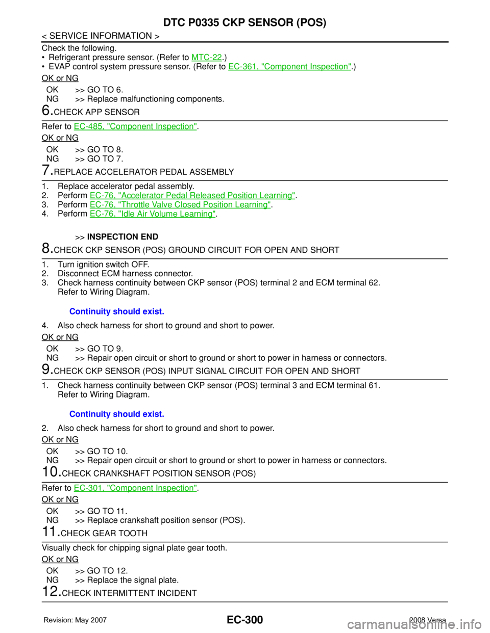
EC-300
< SERVICE INFORMATION >
DTC P0335 CKP SENSOR (POS)
Check the following.
• Refrigerant pressure sensor. (Refer to MTC-22
.)
• EVAP control system pressure sensor. (Refer to EC-361, "
Component Inspection".)
OK or NG
OK >> GO TO 6.
NG >> Replace malfunctioning components.
6.CHECK APP SENSOR
Refer to EC-485, "
Component Inspection".
OK or NG
OK >> GO TO 8.
NG >> GO TO 7.
7.REPLACE ACCELERATOR PEDAL ASSEMBLY
1. Replace accelerator pedal assembly.
2. Perform EC-76, "
Accelerator Pedal Released Position Learning".
3. Perform EC-76, "
Throttle Valve Closed Position Learning".
4. Perform EC-76, "
Idle Air Volume Learning".
>>INSPECTION END
8.CHECK CKP SENSOR (POS) GROUND CIRCUIT FOR OPEN AND SHORT
1. Turn ignition switch OFF.
2. Disconnect ECM harness connector.
3. Check harness continuity between CKP sensor (POS) terminal 2 and ECM terminal 62.
Refer to Wiring Diagram.
4. Also check harness for short to ground and short to power.
OK or NG
OK >> GO TO 9.
NG >> Repair open circuit or short to ground or short to power in harness or connectors.
9.CHECK CKP SENSOR (POS) INPUT SIGNAL CIRCUIT FOR OPEN AND SHORT
1. Check harness continuity between CKP sensor (POS) terminal 3 and ECM terminal 61.
Refer to Wiring Diagram.
2. Also check harness for short to ground and short to power.
OK or NG
OK >> GO TO 10.
NG >> Repair open circuit or short to ground or short to power in harness or connectors.
10.CHECK CRANKSHAFT POSITION SENSOR (POS)
Refer to EC-301, "
Component Inspection".
OK or NG
OK >> GO TO 11.
NG >> Replace crankshaft position sensor (POS).
11 .CHECK GEAR TOOTH
Visually check for chipping signal plate gear tooth.
OK or NG
OK >> GO TO 12.
NG >> Replace the signal plate.
12.CHECK INTERMITTENT INCIDENTContinuity should exist.
Continuity should exist.
Page 1378 of 2771
EC-304
< SERVICE INFORMATION >
DTC P0340 CMP SENSOR (PHASE)
Wiring Diagram
INFOID:0000000001702812
Specification data are reference values and are measured between each terminal and ground.
Pulse signal is measured by CONSULT-II.
CAUTION:
BBWA2639E