2008 NISSAN LATIO turn signal
[x] Cancel search: turn signalPage 101 of 2771
DTC P0705 PARK/NEUTRAL POSITION (PNP) SWITCH
AT-89
< SERVICE INFORMATION >
D
E
F
G
H
I
J
K
L
MA
B
AT
N
O
P
NG >> GO TO 3.
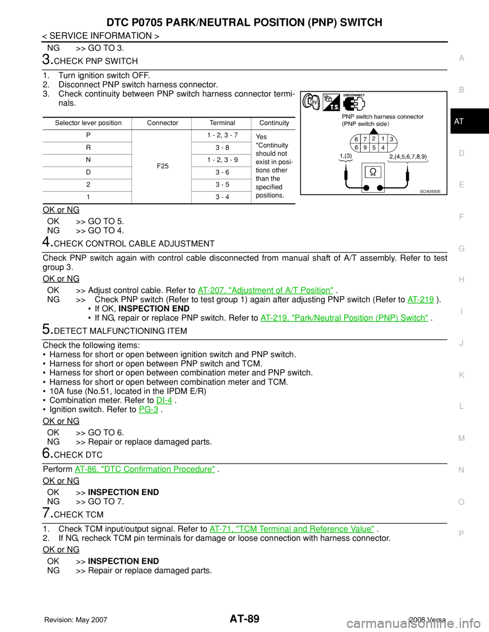
3.CHECK PNP SWITCH
1. Turn ignition switch OFF.
2. Disconnect PNP switch harness connector.
3. Check continuity between PNP switch harness connector termi-
nals.
OK or NG
OK >> GO TO 5.
NG >> GO TO 4.
4.CHECK CONTROL CABLE ADJUSTMENT
Check PNP switch again with control cable disconnected from manual shaft of A/T assembly. Refer to test
group 3.
OK or NG
OK >> Adjust control cable. Refer to AT-207, "Adjustment of A/T Position" .
NG >> Check PNP switch (Refer to test group 1) again after adjusting PNP switch (Refer to AT-219
).
• If OK, INSPECTION END
• If NG, repair or replace PNP switch. Refer to AT-219, "
Park/Neutral Position (PNP) Switch" .
5.DETECT MALFUNCTIONING ITEM
Check the following items:
• Harness for short or open between ignition switch and PNP switch.
• Harness for short or open between PNP switch and TCM.
• Harness for short or open between combination meter and PNP switch.
• Harness for short or open between combination meter and TCM.
• 10A fuse (No.51, located in the IPDM E/R)
• Combination meter. Refer to DI-4
.
• Ignition switch. Refer to PG-3
.
OK or NG
OK >> GO TO 6.
NG >> Repair or replace damaged parts.
6.CHECK DTC
Perform AT-86, "
DTC Confirmation Procedure" .
OK or NG
OK >>INSPECTION END
NG >> GO TO 7.
7.CHECK TCM
1. Check TCM input/output signal. Refer to AT-71, "
TCM Terminal and Reference Value" .
2. If NG, recheck TCM pin terminals for damage or loose connection with harness connector.
OK or NG
OK >>INSPECTION END
NG >> Repair or replace damaged parts.
Selector lever position Connector Terminal Continuity
P
F251 - 2, 3 - 7
Ye s
*Continuity
should not
exist in posi-
tions other
than the
specified
positions. R3 - 8
N 1 - 2, 3 - 9
D3 - 6
23 - 5
13 - 4
SCIA3553E
Page 103 of 2771
DTC P0710 A/T FLUID TEMPERATURE SENSOR CIRCUIT
AT-91
< SERVICE INFORMATION >
D
E
F
G
H
I
J
K
L
MA
B
AT
N
O
P
DTC P0710 A/T FLUID TEMPERATURE SENSOR CIRCUIT
DescriptionINFOID:0000000001703209
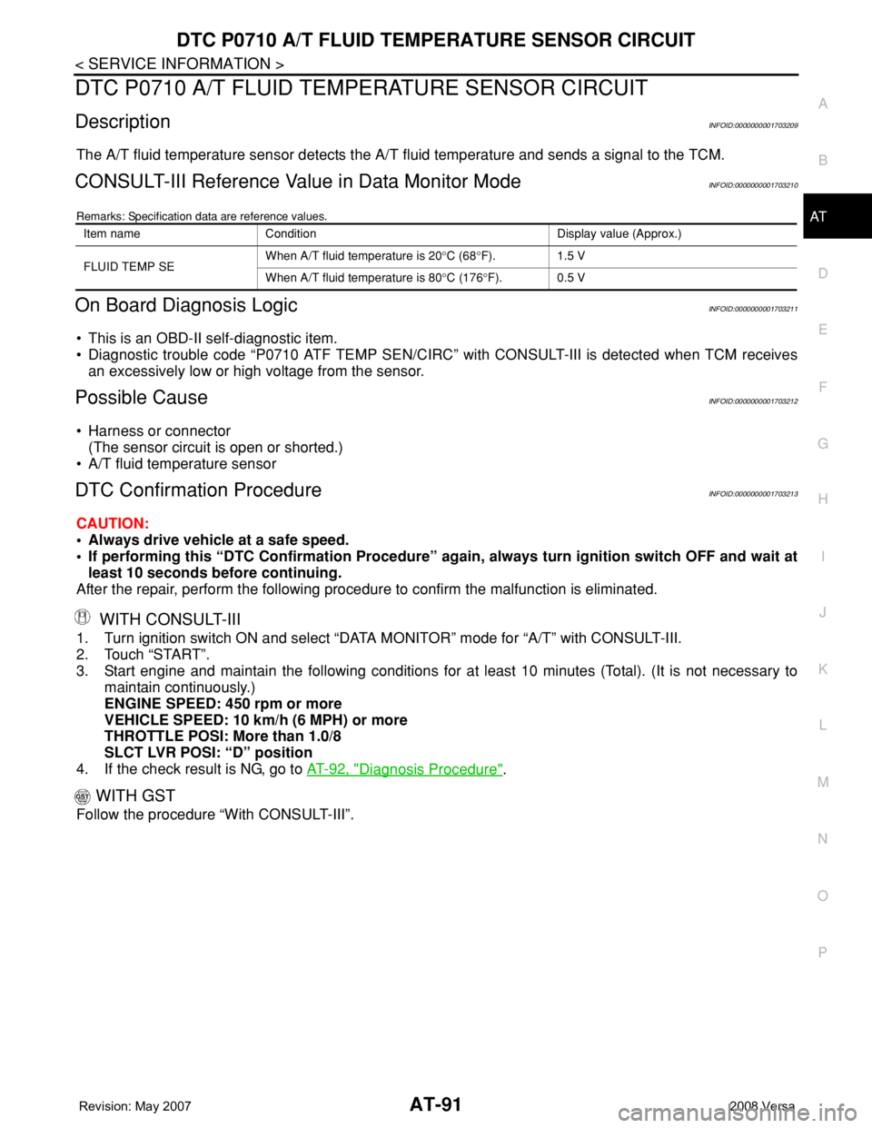
The A/T fluid temperature sensor detects the A/T fluid temperature and sends a signal to the TCM.
CONSULT-III Reference Value in Data Monitor ModeINFOID:0000000001703210
Remarks: Specification data are reference values.
On Board Diagnosis LogicINFOID:0000000001703211
• This is an OBD-II self-diagnostic item.
• Diagnostic trouble code “P0710 ATF TEMP SEN/CIRC” with CONSULT-III is detected when TCM receives
an excessively low or high voltage from the sensor.
Possible CauseINFOID:0000000001703212
• Harness or connector
(The sensor circuit is open or shorted.)
• A/T fluid temperature sensor
DTC Confirmation ProcedureINFOID:0000000001703213
CAUTION:
• Always drive vehicle at a safe speed.
• If performing this “DTC Confirmation Procedure” again, always turn ignition switch OFF and wait at
least 10 seconds before continuing.
After the repair, perform the following procedure to confirm the malfunction is eliminated.
WITH CONSULT-III
1. Turn ignition switch ON and select “DATA MONITOR” mode for “A/T” with CONSULT-III.
2. Touch “START”.
3. Start engine and maintain the following conditions for at least 10 minutes (Total). (It is not necessary to
maintain continuously.)
ENGINE SPEED: 450 rpm or more
VEHICLE SPEED: 10 km/h (6 MPH) or more
THROTTLE POSI: More than 1.0/8
SLCT LVR POSI: “D” position
4. If the check result is NG, go to AT-92, "
Diagnosis Procedure".
WITH GST
Follow the procedure “With CONSULT-III”.
Item name Condition Display value (Approx.)
FLUID TEMP SEWhen A/T fluid temperature is 20°C (68°F). 1.5 V
When A/T fluid temperature is 80°C (176°F). 0.5 V
Page 105 of 2771
DTC P0710 A/T FLUID TEMPERATURE SENSOR CIRCUIT
AT-93
< SERVICE INFORMATION >
D
E
F
G
H
I
J
K
L
MA
B
AT
N
O
P
With CONSULT-III
1. Start engine.
2. Select “TCM INPUT SIGNALS” in “DATA MONITOR” mode for “A/T” with CONSULT-III.
3. Read out the value of “FLUID TEMP SE”.
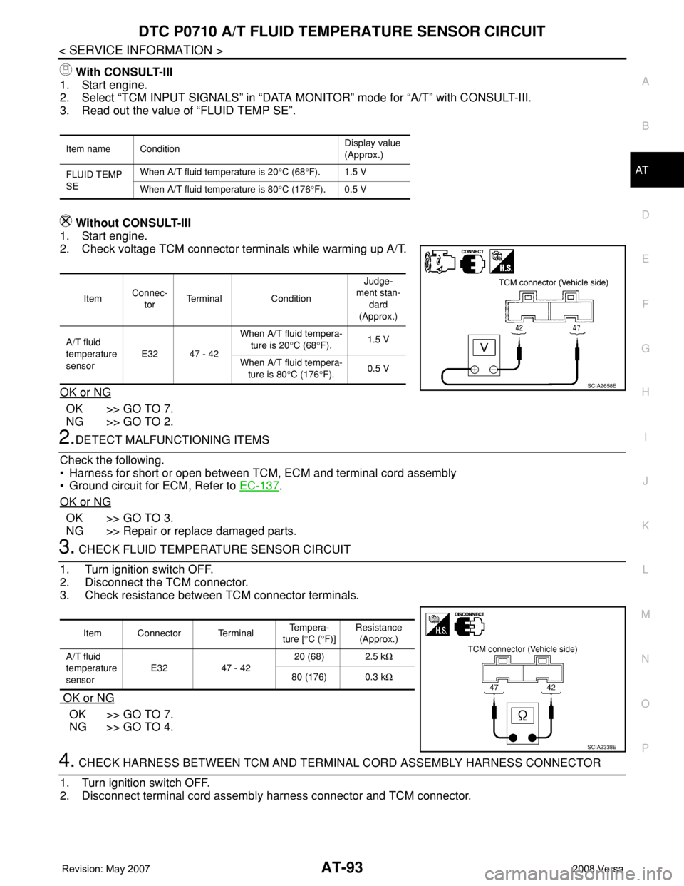
Without CONSULT-III
1. Start engine.
2. Check voltage TCM connector terminals while warming up A/T.
OK or NG
OK >> GO TO 7.
NG >> GO TO 2.
2.DETECT MALFUNCTIONING ITEMS
Check the following.
• Harness for short or open between TCM, ECM and terminal cord assembly
• Ground circuit for ECM, Refer to EC-137
.
OK or NG
OK >> GO TO 3.
NG >> Repair or replace damaged parts.
3. CHECK FLUID TEMPERATURE SENSOR CIRCUIT
1. Turn ignition switch OFF.
2. Disconnect the TCM connector.
3. Check resistance between TCM connector terminals.
OK or NG
OK >> GO TO 7.
NG >> GO TO 4.
4. CHECK HARNESS BETWEEN TCM AND TERMINAL CORD ASSEMBLY HARNESS CONNECTOR
1. Turn ignition switch OFF.
2. Disconnect terminal cord assembly harness connector and TCM connector.
Item name ConditionDisplay value
(Approx.)
FLUID TEMP
SEWhen A/T fluid temperature is 20°C (68°F). 1.5 V
When A/T fluid temperature is 80°C (176°F). 0.5 V
ItemConnec-
torTerminal ConditionJudge-
ment stan-
dard
(Approx.)
A/T fluid
temperature
sensorE32 47 - 42When A/T fluid tempera-
ture is 20°C (68°F).1.5 V
When A/T fluid tempera-
ture is 80°C (176°F).0.5 V
SCIA2658E
Item Connector Terminal Te m p e r a -
ture [°C (°F)]Resistance
(Approx.)
A/T fluid
temperature
sensorE32 47 - 4220 (68) 2.5 kΩ
80 (176) 0.3 kΩ
SCIA2338E
Page 108 of 2771
AT-96
< SERVICE INFORMATION >
DTC P0720 VEHICLE SPEED SENSOR A/T (REVOLUTION SENSOR)
DTC P0720 VEHICLE SPEED SENSOR A/T (REVOLUTION SENSOR)
DescriptionINFOID:0000000001703217
The revolution sensor detects the revolution of the idler gear parking pawl lock gear and emits a pulse signal.
The pulse signal is sent to the TCM which converts it into vehicle speed.
CONSULT-III Reference Value in Data Monitor ModeINFOID:0000000001703218
Remarks: Specification data are reference values.
On Board Diagnosis LogicINFOID:0000000001703219
• This is an OBD-II self-diagnostic item.
• Diagnostic trouble code “P0720 VHCL SPEED SEN-AT” with CONSULT-III or 1st judgement flicker without
CONSULT-III is detected when TCM does not receive the proper voltage signal from the sensor.
Possible CauseINFOID:0000000001703220
• Harness or connector
(The sensor circuit is open or shorted.)
• Revolution sensor
DTC Confirmation ProcedureINFOID:0000000001703221
CAUTION:
• Always drive vehicle at a safe speed.
• Be careful not to rev engine into the red zone on the tachometer.
• If performing this “DTC Confirmation Procedure” again, always turn ignition switch OFF and wait at
least 10 seconds before continuing.
After the repair, perform the following procedure to confirm the malfunction is eliminated.
WITH CONSULT-III
1. Turn ignition switch ON and select “DATA MONITOR” mode for “A/T” with CONSULT-III.
2. Touch “START”.
3. Drive vehicle and check for an increase of “VHCL/S SE-MTR” value.
If the check result is NG, go to AT-98, "
Diagnosis Procedure" .
If the check result is OK, go to following step.
4. Select “DATA MONITOR” mode for “A/T” with CONSULT-III.
5. Touch “START”.
6. Start engine and maintain the following conditions for at least 5 consecutive seconds.
VEHICLE SPEED: 30 km/h (19 MPH) or more
THROTTLE POSI: More than 1.0/8
SLCT LVR POSI: “D” position
Driving location: Driving the vehicle uphill (increased engine load) will help maintain the driving
conditions required for this test.
If the check result is NG, go to AT-98, "
Diagnosis Procedure" .
If the check result is OK, go to following step.
7. Maintain the following conditions for at least 5 consecutive seconds.
ENGINE SPEED: 3,500 rpm or more
THROTTLE POSI: More than 1.0/8
SLCT LVR POSI: “D” position
Driving location: Driving the vehicle uphill (increased engine load) will help maintain the driving
conditions required for this test.
WITH GST
Follow the procedure “WITH CONSULT-III”.
WITHOUT CONSULT-III
1. Start engine.
Item name Condition Display value
VHCL/S SE-A/T During driving Approximately matches the speedometer reading.
Page 110 of 2771
AT-98
< SERVICE INFORMATION >
DTC P0720 VEHICLE SPEED SENSOR A/T (REVOLUTION SENSOR)
TCM TERMINALS AND REFERENCE VALUES
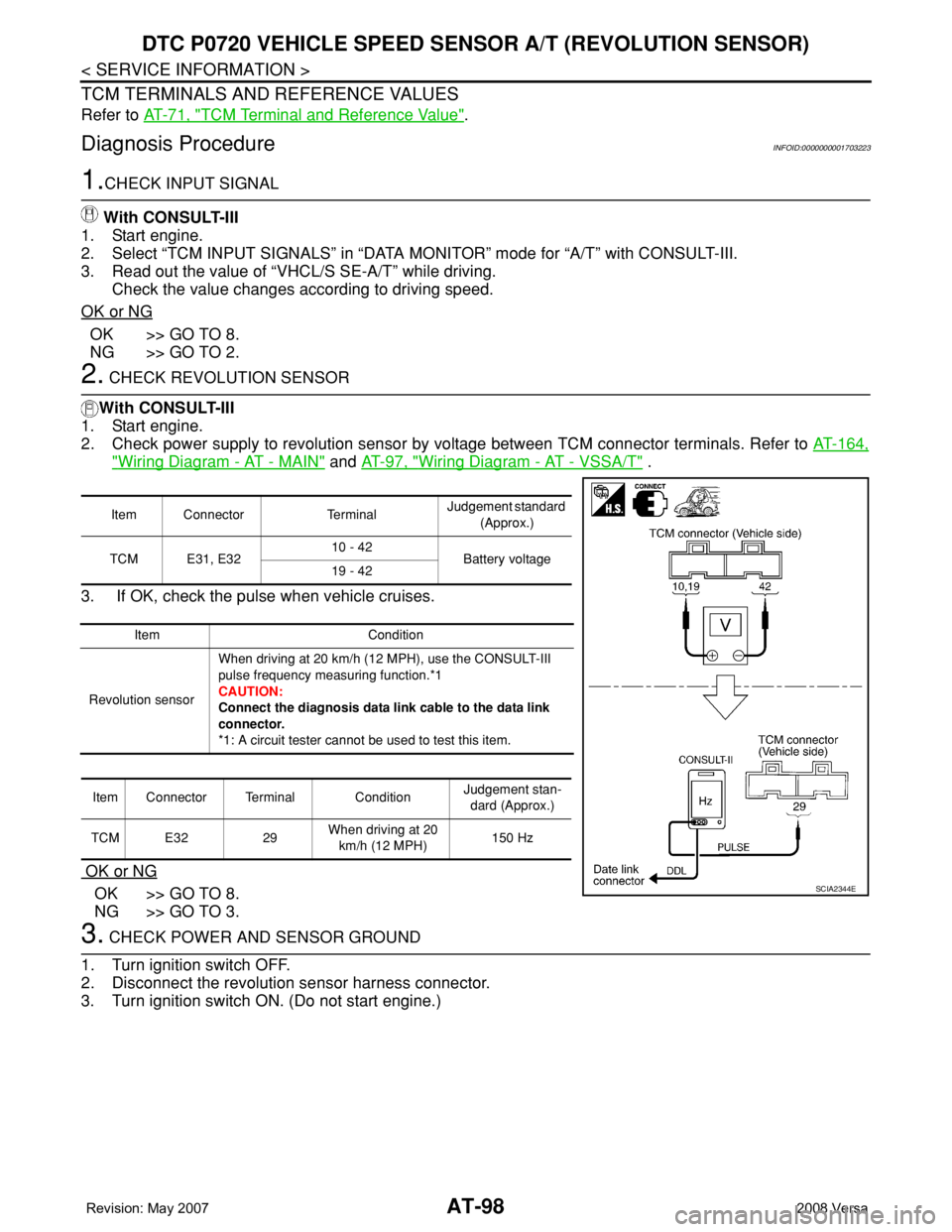
Refer to AT-71, "TCM Terminal and Reference Value".
Diagnosis ProcedureINFOID:0000000001703223
1.CHECK INPUT SIGNAL
With CONSULT-III
1. Start engine.
2. Select “TCM INPUT SIGNALS” in “DATA MONITOR” mode for “A/T” with CONSULT-III.
3. Read out the value of “VHCL/S SE-A/T” while driving.
Check the value changes according to driving speed.
OK or NG
OK >> GO TO 8.
NG >> GO TO 2.
2. CHECK REVOLUTION SENSOR
With CONSULT-III
1. Start engine.
2. Check power supply to revolution sensor by voltage between TCM connector terminals. Refer to AT-164,
"Wiring Diagram - AT - MAIN" and AT-97, "Wiring Diagram - AT - VSSA/T" .
3. If OK, check the pulse when vehicle cruises.
OK or NG
OK >> GO TO 8.
NG >> GO TO 3.
3. CHECK POWER AND SENSOR GROUND
1. Turn ignition switch OFF.
2. Disconnect the revolution sensor harness connector.
3. Turn ignition switch ON. (Do not start engine.)
Item Connector TerminalJudgement standard
(Approx.)
TCM E31, E3210 - 42
Battery voltage
19 - 42
Item Condition
Revolution sensorWhen driving at 20 km/h (12 MPH), use the CONSULT-III
pulse frequency measuring function.*1
CAUTION:
Connect the diagnosis data link cable to the data link
connector.
*1: A circuit tester cannot be used to test this item.
Item Connector Terminal ConditionJudgement stan-
dard (Approx.)
TCM E32 29When driving at 20
km/h (12 MPH)150 Hz
SCIA2344E
Page 111 of 2771
DTC P0720 VEHICLE SPEED SENSOR A/T (REVOLUTION SENSOR)
AT-99
< SERVICE INFORMATION >
D
E
F
G
H
I
J
K
L
MA
B
AT
N
O
P
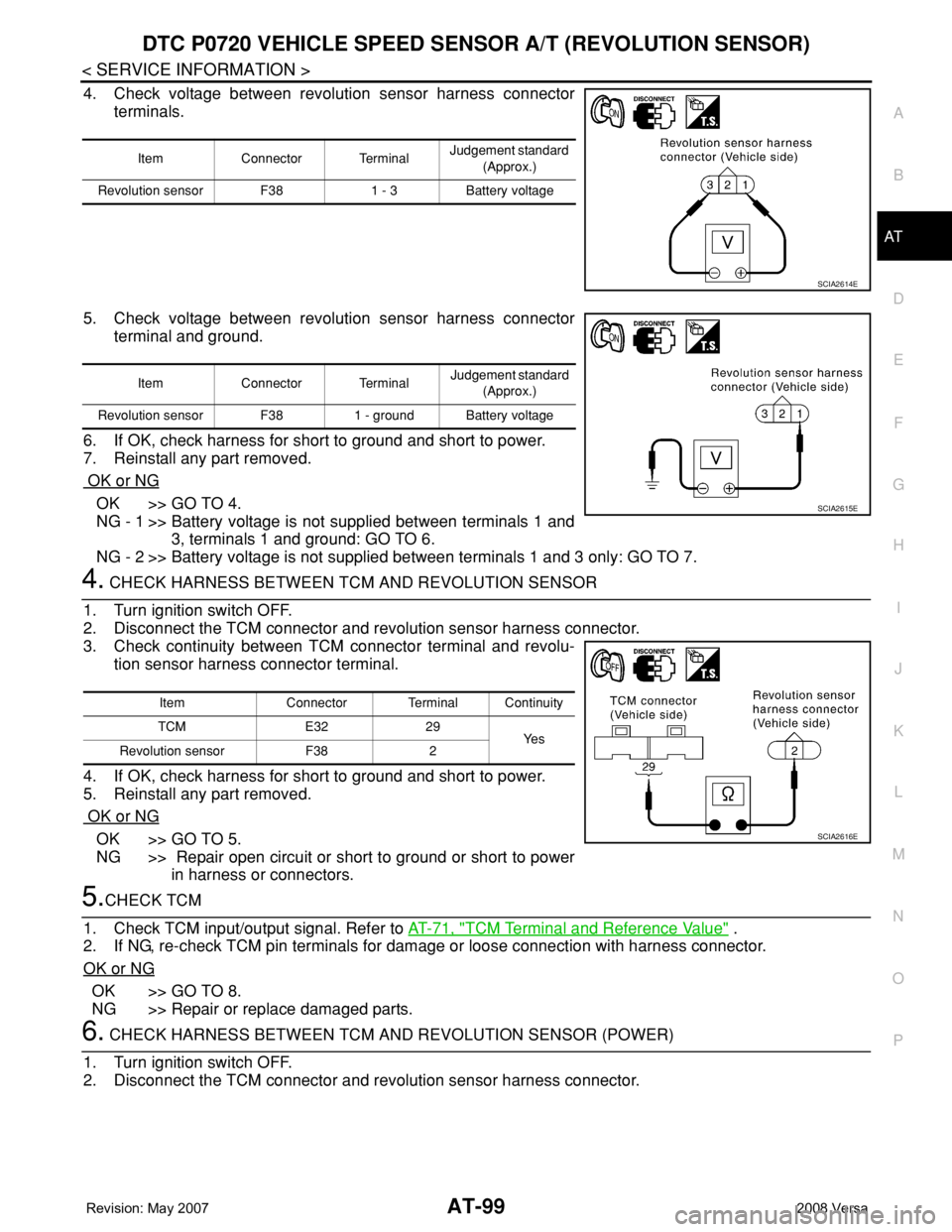
4. Check voltage between revolution sensor harness connector
terminals.
5. Check voltage between revolution sensor harness connector
terminal and ground.
6. If OK, check harness for short to ground and short to power.
7. Reinstall any part removed.
OK or NG
OK >> GO TO 4.
NG - 1 >> Battery voltage is not supplied between terminals 1 and
3, terminals 1 and ground: GO TO 6.
NG - 2 >> Battery voltage is not supplied between terminals 1 and 3 only: GO TO 7.
4. CHECK HARNESS BETWEEN TCM AND REVOLUTION SENSOR
1. Turn ignition switch OFF.
2. Disconnect the TCM connector and revolution sensor harness connector.
3. Check continuity between TCM connector terminal and revolu-
tion sensor harness connector terminal.
4. If OK, check harness for short to ground and short to power.
5. Reinstall any part removed.
OK or NG
OK >> GO TO 5.
NG >> Repair open circuit or short to ground or short to power
in harness or connectors.
5.CHECK TCM
1. Check TCM input/output signal. Refer to AT-71, "
TCM Terminal and Reference Value" .
2. If NG, re-check TCM pin terminals for damage or loose connection with harness connector.
OK or NG
OK >> GO TO 8.
NG >> Repair or replace damaged parts.
6. CHECK HARNESS BETWEEN TCM AND REVOLUTION SENSOR (POWER)
1. Turn ignition switch OFF.
2. Disconnect the TCM connector and revolution sensor harness connector.
Item Connector TerminalJudgement standard
(Approx.)
Revolution sensor F38 1 - 3 Battery voltage
SCIA2614E
Item Connector Terminal Judgement standard
(Approx.)
Revolution sensor F38 1 - ground Battery voltage
SCIA2615E
Item Connector Terminal Continuity
TCM E32 29
Ye s
Revolution sensor F38 2
SCIA2616E
Page 113 of 2771
DTC P0725 ENGINE SPEED SIGNAL
AT-101
< SERVICE INFORMATION >
D
E
F
G
H
I
J
K
L
MA
B
AT
N
O
P
DTC P0725 ENGINE SPEED SIGNAL
DescriptionINFOID:0000000001703224
The engine speed signal is sent from the ECM to the TCM.
CONSULT-III Reference Value in Data Monitor ModeINFOID:0000000001703225
Remarks: Specification data are reference values.
On Board Diagnosis LogicINFOID:0000000001703226
• This is an OBD-II self-diagnostic item.
• Diagnostic trouble code “P0725 ENGINE SPEED SIG” with CONSULT-III or 9th judgement flicker without
CONSULT-III is detected when TCM does not receive the proper voltage signal from ECM.
Possible CauseINFOID:0000000001703227
Harness or connector
(Circuit is open or shorted.)
DTC Confirmation ProcedureINFOID:0000000001703228
CAUTION:
• Always drive vehicle at a safe speed.
• If performing this “DTC Confirmation Procedure” again, always turn ignition switch OFF and wait at
least 10 seconds before continuing.
After the repair, perform the following procedure to confirm the malfunction is eliminated.
WITH CONSULT-III
1. Turn ignition switch ON and select “DATA MONITOR” mode for “A/T” with CONSULT-III.
2. Touch “START”.
3. Start engine and maintain the following conditions for at least 10 consecutive seconds.
VEHICLE SPEED: 10 km/h (6 MPH) or more
THROTTLE POSI: More than 1.0/8
SLCT LVR POSI: “D” position
4. If the check result is NG, go to AT-103, "
Diagnosis Procedure" .
WITH GST
Follow the procedure “WITH CONSULT-III”.
WITHOUT CONSULT-III
1. Start engine.
2. Drive vehicle under the following conditions for more than 10 seconds.
Selector lever position: “D” position
Vehicle speed: Higher than 10 km/h (6 MPH)
Throttle position: Greater than 1.0/8 of the full throttle position
3. Perform self-diagnosis. Refer to AT-78, "
Diagnosis Procedure without CONSULT-III" .
4. If the check result is NG, go to AT-103, "
Diagnosis Procedure" .
Item name Condition Display value
ENGINE SPEED Engine running Approximately matches the tachometer reading.
Page 115 of 2771
DTC P0725 ENGINE SPEED SIGNAL
AT-103
< SERVICE INFORMATION >
D
E
F
G
H
I
J
K
L
MA
B
AT
N
O
P
Diagnosis ProcedureINFOID:0000000001703230
1.CHECK DTC WITH ECM
Check DTC with CONSULT-III “ENGINE”.
Turn ignition switch ON and select “SELF-DIAGNOSTIC RESULTS” mode for “ENGINE” with CONSULT-III.
Refer to EC-109, "
CONSULT-II Function (ENGINE)" .
OK or NG
OK >> GO TO 2.
NG >> Check ignition signal circuit for engine control. Refer to EC-531
.
2.CHECK INPUT SIGNAL
With CONSULT-III
1. Start engine.
2. Select “TCM INPUT SIGNALS” in “DATA MONITOR” mode for “A/T” with CONSULT-III.
3. Read out the value of “ENGINE SPEED”. Check engine speed changes according to throttle position.
Without CONSULT-III
1. Start engine.
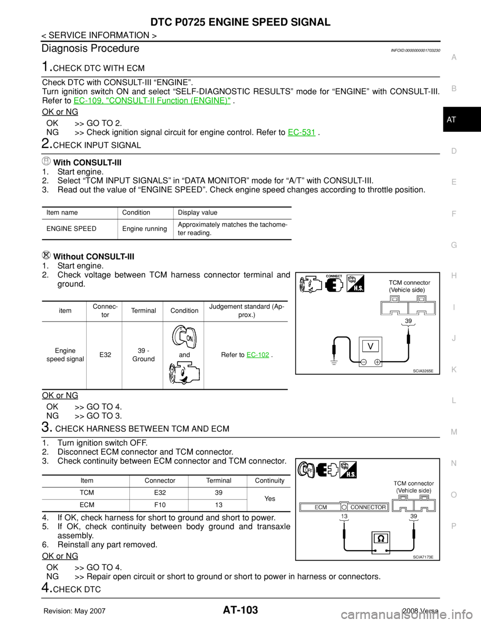
2. Check voltage between TCM harness connector terminal and
ground.
OK or NG
OK >> GO TO 4.
NG >> GO TO 3.
3. CHECK HARNESS BETWEEN TCM AND ECM
1. Turn ignition switch OFF.
2. Disconnect ECM connector and TCM connector.
3. Check continuity between ECM connector and TCM connector.
4. If OK, check harness for short to ground and short to power.
5. If OK, check continuity between body ground and transaxle
assembly.
6. Reinstall any part removed.
OK or NG
OK >> GO TO 4.
NG >> Repair open circuit or short to ground or short to power in harness or connectors.
4.CHECK DTC
Item name Condition Display value
ENGINE SPEED Engine runningApproximately matches the tachome-
ter reading.
itemConnec-
torTerminal ConditionJudgement standard (Ap-
prox.)
Engine
speed signalE3239 -
Ground
and Refer to EC-102
.
SCIA3265E
Item Connector Terminal Continuity
TCM E32 39
Ye s
ECM F10 13
SCIA7173E