2008 NISSAN LATIO service schedule
[x] Cancel search: service schedulePage 1187 of 2771
TROUBLE DIAGNOSIS
EC-113
< SERVICE INFORMATION >
C
D
E
F
G
H
I
J
K
L
MA
EC
N
P O
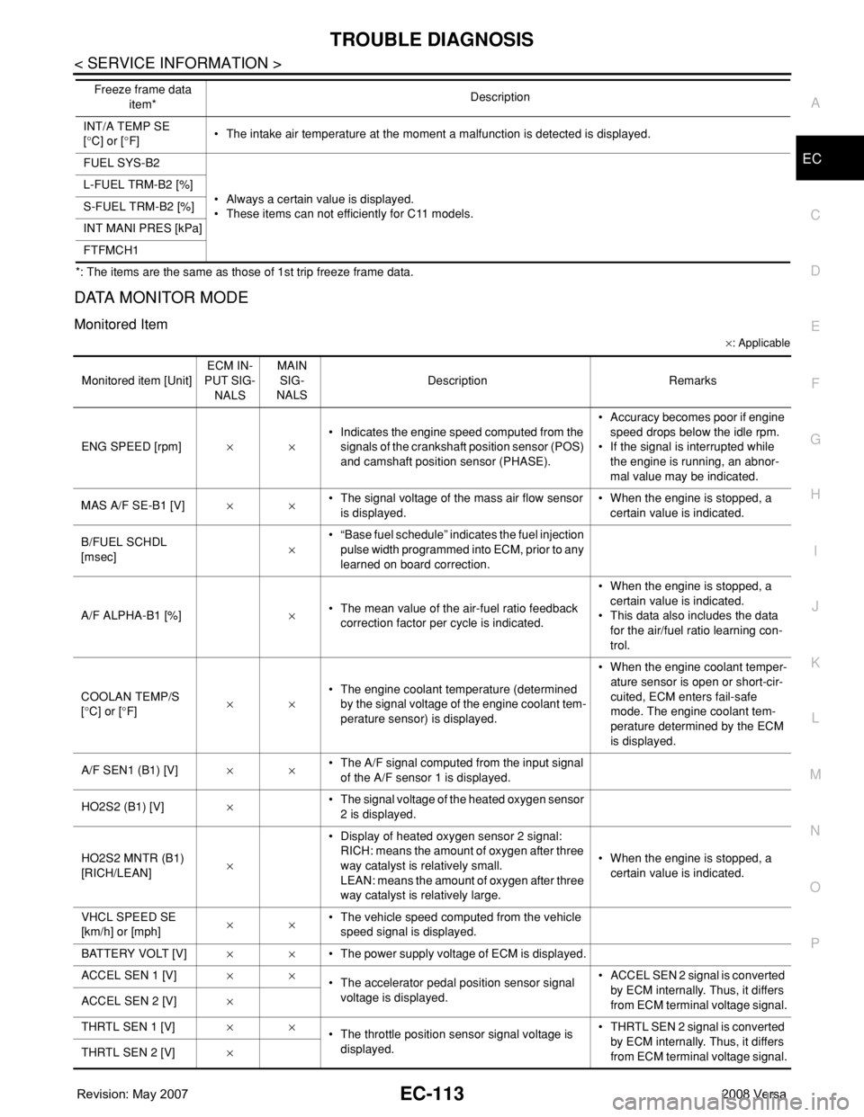
*: The items are the same as those of 1st trip freeze frame data.
DATA MONITOR MODE
Monitored Item
×: Applicable
INT/A TEMP SE
[°C] or [°F]• The intake air temperature at the moment a malfunction is detected is displayed.
FUEL SYS-B2
• Always a certain value is displayed.
• These items can not efficiently for C11 models. L-FUEL TRM-B2 [%]
S-FUEL TRM-B2 [%]
INT MANI PRES [kPa]
FTFMCH1Freeze frame data
item*Description
Monitored item [Unit]ECM IN-
PUT SIG-
NALSMAIN
SIG-
NALSDescription Remarks
ENG SPEED [rpm]×ו Indicates the engine speed computed from the
signals of the crankshaft position sensor (POS)
and camshaft position sensor (PHASE).• Accuracy becomes poor if engine
speed drops below the idle rpm.
• If the signal is interrupted while
the engine is running, an abnor-
mal value may be indicated.
MAS A/F SE-B1 [V]×ו The signal voltage of the mass air flow sensor
is displayed.• When the engine is stopped, a
certain value is indicated.
B/FUEL SCHDL
[msec]ו “Base fuel schedule” indicates the fuel injection
pulse width programmed into ECM, prior to any
learned on board correction.
A/F ALPHA-B1 [%]ו The mean value of the air-fuel ratio feedback
correction factor per cycle is indicated.• When the engine is stopped, a
certain value is indicated.
• This data also includes the data
for the air/fuel ratio learning con-
trol.
COOLAN TEMP/S
[°C] or [°F]×ו The engine coolant temperature (determined
by the signal voltage of the engine coolant tem-
perature sensor) is displayed.• When the engine coolant temper-
ature sensor is open or short-cir-
cuited, ECM enters fail-safe
mode. The engine coolant tem-
perature determined by the ECM
is displayed.
A/F SEN1 (B1) [V]×ו The A/F signal computed from the input signal
of the A/F sensor 1 is displayed.
HO2S2 (B1) [V]ו The signal voltage of the heated oxygen sensor
2 is displayed.
HO2S2 MNTR (B1)
[RICH/LEAN]ו Display of heated oxygen sensor 2 signal:
RICH: means the amount of oxygen after three
way catalyst is relatively small.
LEAN: means the amount of oxygen after three
way catalyst is relatively large.• When the engine is stopped, a
certain value is indicated.
VHCL SPEED SE
[km/h] or [mph]×ו The vehicle speed computed from the vehicle
speed signal is displayed.
BATTERY VOLT [V]×ו The power supply voltage of ECM is displayed.
ACCEL SEN 1 [V]××
• The accelerator pedal position sensor signal
voltage is displayed.• ACCEL SEN 2 signal is converted
by ECM internally. Thus, it differs
from ECM terminal voltage signal. ACCEL SEN 2 [V]×
THRTL SEN 1 [V]××
• The throttle position sensor signal voltage is
displayed.• THRTL SEN 2 signal is converted
by ECM internally. Thus, it differs
from ECM terminal voltage signal. THRTL SEN 2 [V]×
Page 1191 of 2771
TROUBLE DIAGNOSIS
EC-117
< SERVICE INFORMATION >
C
D
E
F
G
H
I
J
K
L
MA
EC
N
P O
NOTE:
Any monitored item that does not match the vehicle being diagnosed is deleted from the display automatically.
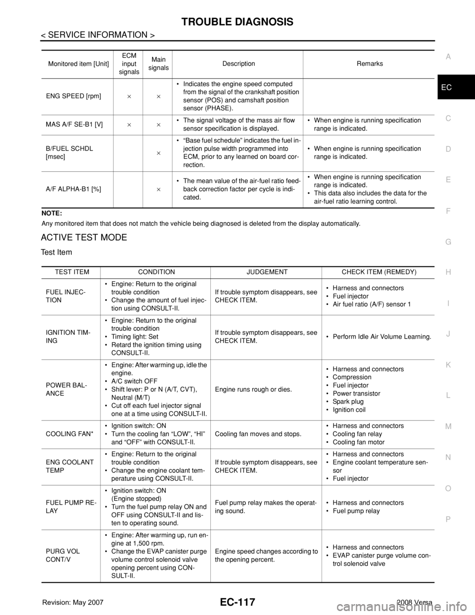
ACTIVE TEST MODE
Test Item
Monitored item [Unit]ECM
input
signalsMain
signalsDescription Remarks
ENG SPEED [rpm]×ו Indicates the engine speed computed
from the signal of the crankshaft position
sensor (POS) and camshaft position
sensor (PHASE).
MAS A/F SE-B1 [V]×ו The signal voltage of the mass air flow
sensor specification is displayed.• When engine is running specification
range is indicated.
B/FUEL SCHDL
[msec]ו “Base fuel schedule” indicates the fuel in-
jection pulse width programmed into
ECM, prior to any learned on board cor-
rection.• When engine is running specification
range is indicated.
A/F ALPHA-B1 [%]ו The mean value of the air-fuel ratio feed-
back correction factor per cycle is indi-
cated.• When engine is running specification
range is indicated.
• This data also includes the data for the
air-fuel ratio learning control.
TEST ITEM CONDITION JUDGEMENT CHECK ITEM (REMEDY)
FUEL INJEC-
TION• Engine: Return to the original
trouble condition
• Change the amount of fuel injec-
tion using CONSULT-II.If trouble symptom disappears, see
CHECK ITEM.• Harness and connectors
• Fuel injector
• Air fuel ratio (A/F) sensor 1
IGNITION TIM-
ING• Engine: Return to the original
trouble condition
• Timing light: Set
• Retard the ignition timing using
CONSULT-II.If trouble symptom disappears, see
CHECK ITEM.• Perform Idle Air Volume Learning.
POWER BAL-
ANCE• Engine: After warming up, idle the
engine.
• A/C switch OFF
• Shift lever: P or N (A/T, CVT),
Neutral (M/T)
• Cut off each fuel injector signal
one at a time using CONSULT-II.Engine runs rough or dies.• Harness and connectors
• Compression
• Fuel injector
• Power transistor
•Spark plug
• Ignition coil
COOLING FAN*• Ignition switch: ON
• Turn the cooling fan “LOW”, “HI”
and “OFF” with CONSULT-II.Cooling fan moves and stops.• Harness and connectors
• Cooling fan relay
• Cooling fan motor
ENG COOLANT
TEMP• Engine: Return to the original
trouble condition
• Change the engine coolant tem-
perature using CONSULT-II.If trouble symptom disappears, see
CHECK ITEM.• Harness and connectors
• Engine coolant temperature sen-
sor
• Fuel injector
FUEL PUMP RE-
LAY• Ignition switch: ON
(Engine stopped)
• Turn the fuel pump relay ON and
OFF using CONSULT-II and lis-
ten to operating sound.Fuel pump relay makes the operat-
ing sound.• Harness and connectors
• Fuel pump relay
PURG VOL
CONT/V• Engine: After warming up, run en-
gine at 1,500 rpm.
• Change the EVAP canister purge
volume control solenoid valve
opening percent using CON-
SULT-II.Engine speed changes according to
the opening percent.• Harness and connectors
• EVAP canister purge volume con-
trol solenoid valve
Page 1840 of 2771
FSU-6
< SERVICE INFORMATION >
FRONT SUSPENSION ASSEMBLY
FRONT SUSPENSION ASSEMBLY
On-Vehicle Inspection and ServiceINFOID:0000000001703721
Make sure the mounting conditions (looseness, back lash) of each component and component conditions
(wear, damage) are normal.
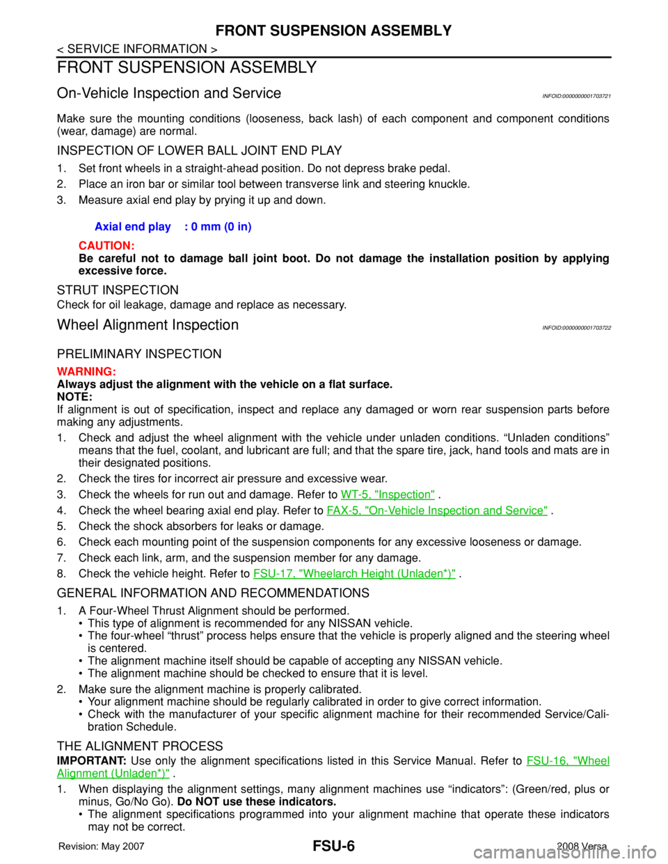
INSPECTION OF LOWER BALL JOINT END PLAY
1. Set front wheels in a straight-ahead position. Do not depress brake pedal.
2. Place an iron bar or similar tool between transverse link and steering knuckle.
3. Measure axial end play by prying it up and down.
CAUTION:
Be careful not to damage ball joint boot. Do not damage the installation position by applying
excessive force.
STRUT INSPECTION
Check for oil leakage, damage and replace as necessary.
Wheel Alignment InspectionINFOID:0000000001703722
PRELIMINARY INSPECTION
WARNING:
Always adjust the alignment with the vehicle on a flat surface.
NOTE:
If alignment is out of specification, inspect and replace any damaged or worn rear suspension parts before
making any adjustments.
1. Check and adjust the wheel alignment with the vehicle under unladen conditions. “Unladen conditions”
means that the fuel, coolant, and lubricant are full; and that the spare tire, jack, hand tools and mats are in
their designated positions.
2. Check the tires for incorrect air pressure and excessive wear.
3. Check the wheels for run out and damage. Refer to WT-5, "
Inspection" .
4. Check the wheel bearing axial end play. Refer to FA X - 5 , "
On-Vehicle Inspection and Service" .
5. Check the shock absorbers for leaks or damage.
6. Check each mounting point of the suspension components for any excessive looseness or damage.
7. Check each link, arm, and the suspension member for any damage.
8. Check the vehicle height. Refer to FSU-17, "
Wheelarch Height (Unladen*)" .
GENERAL INFORMATION AND RECOMMENDATIONS
1. A Four-Wheel Thrust Alignment should be performed.
• This type of alignment is recommended for any NISSAN vehicle.
• The four-wheel “thrust” process helps ensure that the vehicle is properly aligned and the steering wheel
is centered.
• The alignment machine itself should be capable of accepting any NISSAN vehicle.
• The alignment machine should be checked to ensure that it is level.
2. Make sure the alignment machine is properly calibrated.
• Your alignment machine should be regularly calibrated in order to give correct information.
• Check with the manufacturer of your specific alignment machine for their recommended Service/Cali-
bration Schedule.
THE ALIGNMENT PROCESS
IMPORTANT: Use only the alignment specifications listed in this Service Manual. Refer to FSU-16, "Wheel
Alignment (Unladen*)" .
1. When displaying the alignment settings, many alignment machines use “indicators”: (Green/red, plus or
minus, Go/No Go). Do NOT use these indicators.
• The alignment specifications programmed into your alignment machine that operate these indicators
may not be correct.Axial end play : 0 mm (0 in)
Page 2261 of 2771
MA-1
MAINTENANCE
C
D
E
F
G
H
I
J
K
M
SECTION MA
A
B
MA
N
O
P
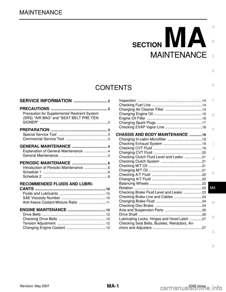
CONTENTS
MAINTENANCE
SERVICE INFORMATION ............................2
PRECAUTIONS ...................................................2
Precaution for Supplemental Restraint System
(SRS) "AIR BAG" and "SEAT BELT PRE-TEN-
SIONER" ...................................................................
2
PREPARATION ...................................................3
Special Service Tool .................................................3
Commercial Service Tool ..........................................3
GENERAL MAINTENANCE ................................4
Explanation of General Maintenance ........................4
General Maintenance ................................................4
PERIODIC MAINTENANCE ................................6
Introduction of Periodic Maintenance ........................6
Schedule 1 ................................................................6
Schedule 2 ................................................................8
RECOMMENDED FLUIDS AND LUBRI-
CANTS ................................................................
10
Fluids and Lubricants ..............................................10
SAE Viscosity Number ............................................10
Anti-freeze Coolant Mixture Ratio ...........................11
ENGINE MAINTENANCE ...................................12
Drive Belts ...............................................................12
Checking Drive Belts ...............................................12
Tension Adjustment ................................................12
Changing Engine Coolant .......................................12
Inspection ................................................................14
Checking Fuel Line ..................................................14
Changing Air Cleaner Filter .....................................14
Changing Engine Oil ................................................15
Engine Oil Filter .......................................................16
Changing Spark Plugs .............................................17
Checking EVAP Vapor Line .....................................18
CHASSIS AND BODY MAINTENANCE ...........19
Changing In-cabin Microfilter ...................................19
Checking Exhaust System .......................................19
Checking CVT Fluid .................................................19
Changing CVT Fluid ................................................20
Checking Clutch Fluid Level and Leaks ..................21
Checking Clutch System .........................................21
Checking M/T Oil .....................................................21
Changing M/T Oil .....................................................21
Checking A/T Fluid ..................................................22
Changing A/T Fluid ..................................................22
Balancing Wheels ....................................................23
Rotation ...................................................................23
Checking Brake Fluid Level and Leaks ...................23
Checking Brake Line and Cables ............................24
Changing Brake Fluid ..............................................24
Checking Disc Brake ...............................................24
Axle and Suspension Parts .....................................25
Drive Shaft ...............................................................26
Lubricating Locks, Hinges and Hood Latch .............27
Checking Seat Belts, Buckles, Retractors, An-
chors and Adjusters .................................................
27
Page 2266 of 2771
MA-6
< SERVICE INFORMATION >
PERIODIC MAINTENANCE
PERIODIC MAINTENANCE
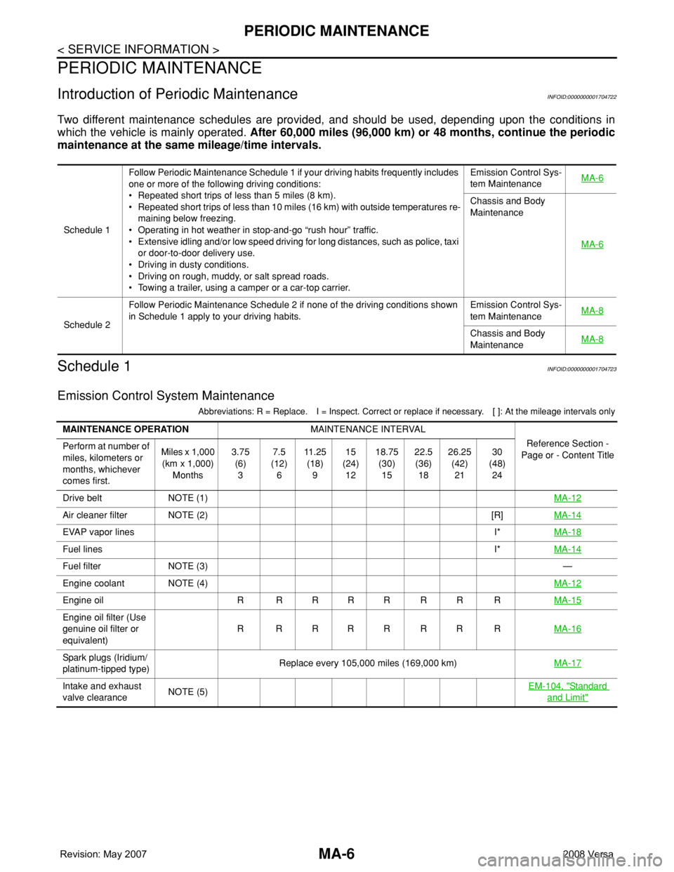
Introduction of Periodic MaintenanceINFOID:0000000001704722
Two different maintenance schedules are provided, and should be used, depending upon the conditions in
which the vehicle is mainly operated. After 60,000 miles (96,000 km) or 48 months, continue the periodic
maintenance at the same mileage/time intervals.
Schedule 1INFOID:0000000001704723
Emission Control System Maintenance
Abbreviations: R = Replace. I = Inspect. Correct or replace if necessary. [ ]: At the mileage intervals only
Schedule 1Follow Periodic Maintenance Schedule 1 if your driving habits frequently includes
one or more of the following driving conditions:
• Repeated short trips of less than 5 miles (8 km).
• Repeated short trips of less than 10 miles (16 km) with outside temperatures re-
maining below freezing.
• Operating in hot weather in stop-and-go “rush hour” traffic.
• Extensive idling and/or low speed driving for long distances, such as police, taxi
or door-to-door delivery use.
• Driving in dusty conditions.
• Driving on rough, muddy, or salt spread roads.
• Towing a trailer, using a camper or a car-top carrier.Emission Control Sys-
tem MaintenanceMA-6
Chassis and Body
Maintenance
MA-6
Schedule 2Follow Periodic Maintenance Schedule 2 if none of the driving conditions shown
in Schedule 1 apply to your driving habits.Emission Control Sys-
tem MaintenanceMA-8Chassis and Body
MaintenanceMA-8
MAINTENANCE OPERATIONMAINTENANCE INTERVAL
Reference Section -
Page or - Content Title Perform at number of
miles, kilometers or
months, whichever
comes first.Miles x 1,000
(km x 1,000)
Months3.75
(6)
37.5
(12)
611 . 2 5
(18)
915
(24)
1218.75
(30)
1522.5
(36)
1826.25
(42)
2130
(48)
24
Drive belt NOTE (1)MA-12
Air cleaner filter NOTE (2) [R]MA-14
EVAP vapor linesI*MA-18
Fuel linesI*MA-14
Fuel filter NOTE (3)—
Engine coolant NOTE (4)MA-12
Engine oil R R R R R R R RMA-15
Engine oil filter (Use
genuine oil filter or
equivalent)RRRRRRRRMA-16
Spark plugs (Iridium/
platinum-tipped type)Replace every 105,000 miles (169,000 km)MA-17
Intake and exhaust
valve clearance NOTE (5)EM-104, "Standard
and Limit"
Page 2268 of 2771
MA-8
< SERVICE INFORMATION >
PERIODIC MAINTENANCE
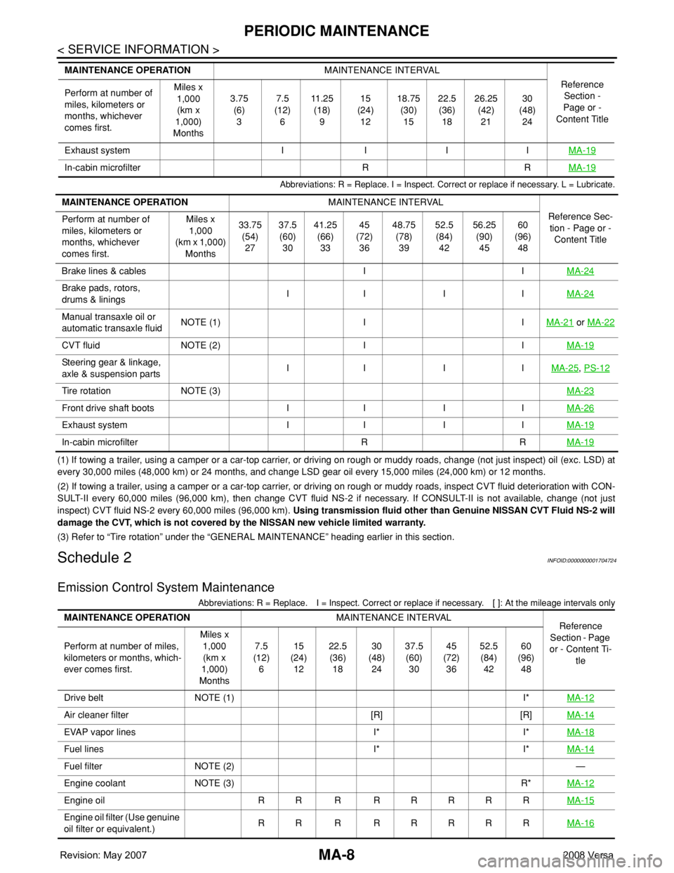
Abbreviations: R = Replace. I = Inspect. Correct or replace if necessary. L = Lubricate.
(1) If towing a trailer, using a camper or a car-top carrier, or driving on rough or muddy roads, change (not just inspect) oil (exc. LSD) at
every 30,000 miles (48,000 km) or 24 months, and change LSD gear oil every 15,000 miles (24,000 km) or 12 months.
(2) If towing a trailer, using a camper or a car-top carrier, or driving on rough or muddy roads, inspect CVT fluid deterioration with CON-
SULT-II every 60,000 miles (96,000 km), then change CVT fluid NS-2 if necessary. If CONSULT-II is not available, change (not just
inspect) CVT fluid NS-2 every 60,000 miles (96,000 km). Using transmission fluid other than Genuine NISSAN CVT Fluid NS-2 will
damage the CVT, which is not covered by the NISSAN new vehicle limited warranty.
(3) Refer to “Tire rotation” under the “GENERAL MAINTENANCE” heading earlier in this section.
Schedule 2INFOID:0000000001704724
Emission Control System Maintenance
Abbreviations: R = Replace. I = Inspect. Correct or replace if necessary. [ ]: At the mileage intervals only
Exhaust system I I I IMA-19
In-cabin microfilter R RMA-19
MAINTENANCE OPERATIONMAINTENANCE INTERVAL
Reference
Section -
Page or -
Content Title Perform at number of
miles, kilometers or
months, whichever
comes first.Miles x
1,000
(km x
1,000)
Months3.75
(6)
37.5
(12)
611 . 2 5
(18)
915
(24)
1218.75
(30)
1522.5
(36)
1826.25
(42)
2130
(48)
24
MAINTENANCE OPERATIONMAINTENANCE INTERVAL
Reference Sec-
tion - Page or -
Content Title Perform at number of
miles, kilometers or
months, whichever
comes first.Miles x
1,000
(km x 1,000)
Months33.75
(54)
2737.5
(60)
3041.25
(66)
3345
(72)
3648.75
(78)
3952.5
(84)
4256.25
(90)
4560
(96)
48
Brake lines & cables I IMA-24
Brake pads, rotors,
drums & liningsII I IMA-24
Manual transaxle oil or
automatic transaxle fluidNOTE (1) I IMA-21 or MA-22
CVT fluid NOTE (2) I IMA-19
Steering gear & linkage,
axle & suspension partsII I IMA-25, PS-12
Tire rotation NOTE (3)MA-23
Front drive shaft boots I I I IMA-26
Exhaust system I I I IMA-19
In-cabin microfilter R RMA-19
MAINTENANCE OPERATIONMAINTENANCE INTERVAL
Reference
Section - Page
or - Content Ti-
tle Perform at number of miles,
kilometers or months, which-
ever comes first.Miles x
1,000
(km x
1,000)
Months7.5
(12)
615
(24)
1222.5
(36)
1830
(48)
2437.5
(60)
3045
(72)
3652.5
(84)
4260
(96)
48
Drive belt NOTE (1) I*MA-12
Air cleaner filter [R] [R]MA-14
EVAP vapor lines I* I*MA-18
Fuel lines I* I*MA-14
Fuel filter NOTE (2)—
Engine coolant NOTE (3) R*MA-12
Engine oil RR R RRRRRMA-15
Engine oil filter (Use genuine
oil filter or equivalent.)RR R RRRRRMA-16
Page 2283 of 2771
CHASSIS AND BODY MAINTENANCE
MA-23
< SERVICE INFORMATION >
C
D
E
F
G
H
I
J
K
MA
B
MA
N
O
P
2. Stop engine.
3. Drain A/T fluid by removing the drain plug. Reinstall the drain plug to the specified torque.
CAUTION:
Do not reuse drain plug gasket.
4. Refill the transaxle with new specified A/T fluid through the A/T fluid charging pipe. Always refill the tran-
saxle with the same volume of A/T fluid that was drained out.
5. Run engine at idle speed for 5 minutes.
6. Check A/T fluid level and condition. Refer to MA-22, "
Checking A/T Fluid" .
Balancing WheelsINFOID:0000000001704749
Adjust wheel balance using road wheel center.
CAUTION:
• Be careful not to scratch the road wheel during removal.
• Use clip-on type wheel balance weights only.
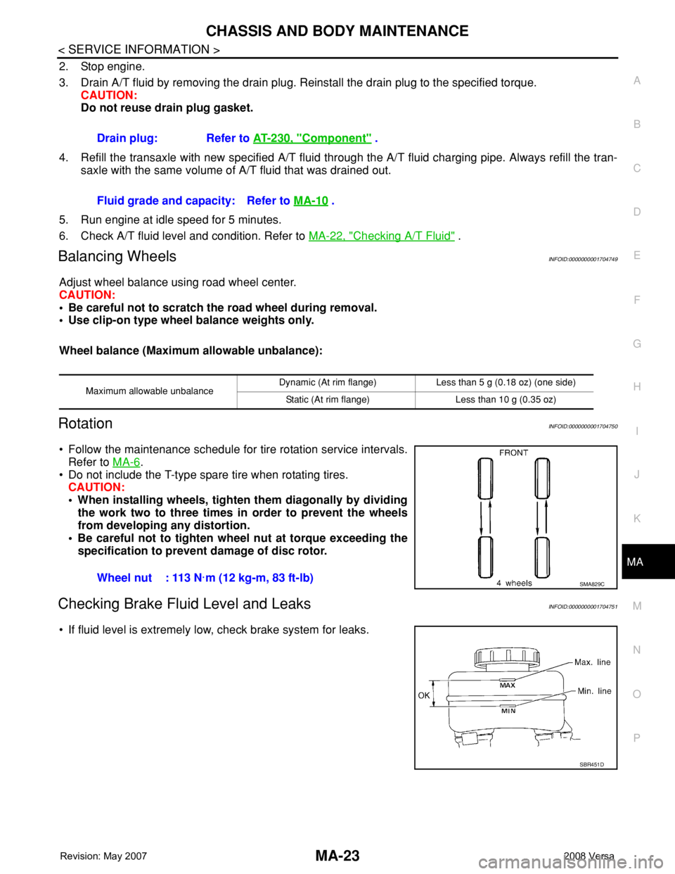
Wheel balance (Maximum allowable unbalance):
RotationINFOID:0000000001704750
• Follow the maintenance schedule for tire rotation service intervals.
Refer to MA-6
.
• Do not include the T-type spare tire when rotating tires.
CAUTION:
• When installing wheels, tighten them diagonally by dividing
the work two to three times in order to prevent the wheels
from developing any distortion.
• Be careful not to tighten wheel nut at torque exceeding the
specification to prevent damage of disc rotor.
Checking Brake Fluid Level and LeaksINFOID:0000000001704751
• If fluid level is extremely low, check brake system for leaks.Drain plug: Refer to AT-230, "
Component" .
Fluid grade and capacity: Refer to MA-10
.
Maximum allowable unbalanceDynamic (At rim flange) Less than 5 g (0.18 oz) (one side)
Static (At rim flange) Less than 10 g (0.35 oz)
Wheel nut : 113 N·m (12 kg-m, 83 ft-lb)SMA829C
SBR451D
Page 2406 of 2771
MTC-68
< SERVICE INFORMATION >
AIR CONDITIONER FILTER
AIR CONDITIONER FILTER
Removal and InstallationINFOID:0000000001704320
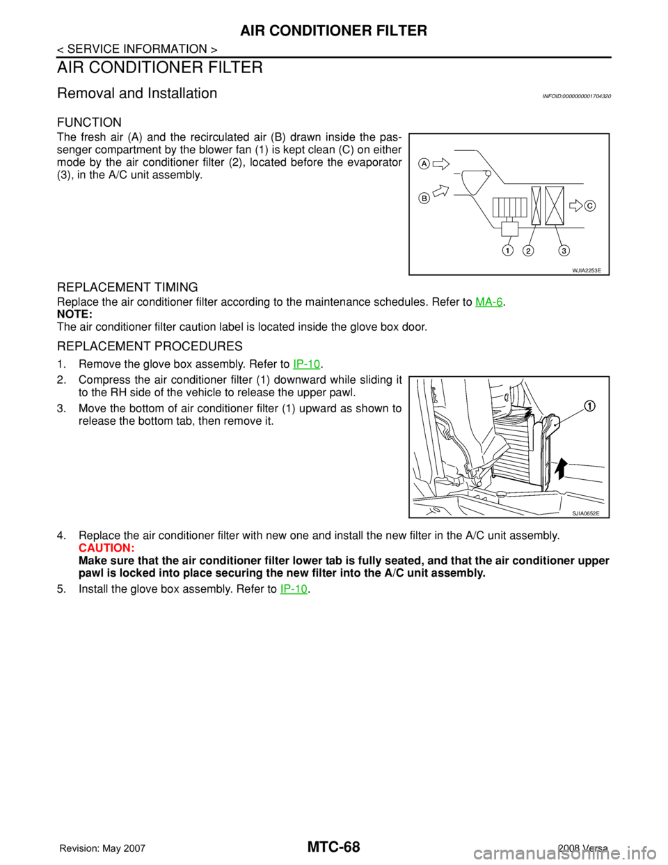
FUNCTION
The fresh air (A) and the recirculated air (B) drawn inside the pas-
senger compartment by the blower fan (1) is kept clean (C) on either
mode by the air conditioner filter (2), located before the evaporator
(3), in the A/C unit assembly.
REPLACEMENT TIMING
Replace the air conditioner filter according to the maintenance schedules. Refer to MA-6.
NOTE:
The air conditioner filter caution label is located inside the glove box door.
REPLACEMENT PROCEDURES
1. Remove the glove box assembly. Refer to IP-10.
2. Compress the air conditioner filter (1) downward while sliding it
to the RH side of the vehicle to release the upper pawl.
3. Move the bottom of air conditioner filter (1) upward as shown to
release the bottom tab, then remove it.
4. Replace the air conditioner filter with new one and install the new filter in the A/C unit assembly.
CAUTION:
Make sure that the air conditioner filter lower tab is fully seated, and that the air conditioner upper
pawl is locked into place securing the new filter into the A/C unit assembly.
5. Install the glove box assembly. Refer to IP-10
.
WJIA2253E
SJIA0652E