Page 827 of 2771
CO-10
< SERVICE INFORMATION >
ENGINE COOLANT
3. Fill radiator and reservoir tank with water and reinstall radiator cap.
4. Run engine and warm it up to normal operating temperature.
5. Rev engine two or three times under no-load.
6. Stop engine and wait until it cools down.
7. Drain water from the cooling system. Refer to CO-8, "
Changing Engine Coolant".
8. Repeat steps 1 through 7 until clear water begins to drain from radiator.
Page 828 of 2771
RADIATOR
CO-11
< SERVICE INFORMATION >
C
D
E
F
G
H
I
J
K
L
MA
CO
N
P O
RADIATOR
ComponentINFOID:0000000001702531
Removal and InstallationINFOID:0000000001702532
WARNING:
1. Reservoir tank cap 2. Reservoir tank 3. Radiator hose (upper)
4. Mounting rubber (upper) 5. Radiator cap 6. Reservoir tank hose
7. Radiator 8. A/T fluid cooler hose 9. Mounting rubber (lower)
10. O-ring 11. Radiator drain plug 12. A/T fluid cooler hose
13. Radiator hose (lower) 14. Cooling fan assembly 15. CVT fluid cooler hose
16. CVT fluid cooler hose A. To water outlet B. To A/T
C. To water inlet D. M/T models E. CVT models
F. Models with A/C G. To CVT
PBIC4720E
Page 830 of 2771

RADIATOR
CO-13
< SERVICE INFORMATION >
C
D
E
F
G
H
I
J
K
L
MA
CO
N
P O
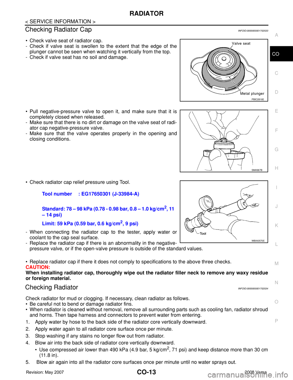
Checking Radiator CapINFOID:0000000001702533
• Check valve seat of radiator cap.
- Check if valve seat is swollen to the extent that the edge of the
plunger cannot be seen when watching it vertically from the top.
- Check if valve seat has no soil and damage.
• Pull negative-pressure valve to open it, and make sure that it is
completely closed when released.
- Make sure that there is no dirt or damage on the valve seat of radi-
ator cap negative-pressure valve.
- Make sure that the valve operates properly in the opening and
closing conditions.
• Check radiator cap relief pressure using Tool.
- When connecting the radiator cap to the tester, apply water or
coolant to the cap seal surface.
- Replace the radiator cap if there is an abnormality in the negative-
pressure valve, or if the open-valve pressure is outside of the standard values.
• Replace radiator cap if there it does not comply to specifications to the above three checks.
CAUTION:
When installing radiator cap, thoroughly wipe out the radiator filler neck to remove any waxy residue
or foreign material.
Checking RadiatorINFOID:0000000001702534
Check radiator for mud or clogging. If necessary, clean radiator as follows.
• Be careful not to bend or damage radiator fins.
• When radiator is cleaned without removal, remove all surrounding parts such as cooling fan, radiator shroud
and horns. Then tape harness and connectors to prevent water from entering.
1. Apply water by hose to the back side of the radiator core vertically downward.
2. Apply water again to all radiator core surface once per minute.
3. Stop washing if any stains no longer flow out from radiator.
4. Blow air into the back side of radiator core vertically downward.
• Use compressed air lower than 490 kPa (4.9 bar, 5 kg/cm
2, 71 psi) and keep distance more than 30 cm
(11.8 in).
5. Blow air again into all the radiator core surfaces once per minute until no water sprays out.
PBIC2816E
SMA967B
Tool number : EG17650301 (J-33984-A)
Standard: 78 – 98 kPa (0.78 - 0.98 bar, 0.8 – 1.0 kg/cm
2, 11
– 14 psi)
Limit: 59 kPa (0.59 bar, 0.6 kg/cm
2, 9 psi)
WBIA0570E
Page 831 of 2771
CO-14
< SERVICE INFORMATION >
COOLING FAN
COOLING FAN
Component (Models with A/C)INFOID:0000000001702535
Component (Models without A/C)INFOID:0000000001702536
1. Fan motor cover 2. Fan motor 3. Cooling fan control module
4. Washer 5. Fan shroud 6. Washer
7. Cooling fan A. Apply on fan motor shaft Front
PBIC4538E
1. Fan motor 2. Fan shroud 3. Cooling fan
A. Apply on fan motor shaft Front
WBIA0786E
Page 832 of 2771

COOLING FAN
CO-15
< SERVICE INFORMATION >
C
D
E
F
G
H
I
J
K
L
MA
CO
N
P O
Removal and InstallationINFOID:0000000001702537
REMOVAL
1. Drain engine coolant from radiator. Refer to CO-8, "Changing Engine Coolant".
CAUTION:
• Perform this step when engine is cold.
• Do not spill engine coolant on drive belt.
2. Remove air duct (inlet). Refer to EM-16, "
Component".
3. Remove reservoir tank. Refer to CO-11, "
Component".
4. Disconnect radiator hose (upper) at radiator side. Refer to CO-11, "
Component".
5. Disconnect harness connectors from fan motor, and move harness to aside.
6. Remove cooling fan assembly.
CAUTION:
Be careful not to damage or scratch the radiator core.
INSTALLATION
Installation is the reverse order of removal.
• Cooling fans are controlled by ECM. For details, refer to EC-412
.
CAUTION:
Be careful not to damage or scratch the radiator core.
DISASSEMBLY AND ASSEMBLYINFOID:0000000001702538
Disassembly
1. Remove cooling fan from fan motor.
2. Remove fan motor from fan shroud.
Inspection After Disassembly
Inspect cooling fan for crack or unusual bend.
• If anything is found, replace cooling fan.
Assembly
Assembly is the reverse order of disassembly.
Page 1166 of 2771
EC-92
< SERVICE INFORMATION >
TROUBLE DIAGNOSIS
1 - 6: The numbers refer to the order of inspection.Cooling Radiator/Hose/Radiator filler cap
55555 55 45CO-11
Thermostat 5CO-17
Water pumpCO-16
Water galleryCO-7
Cooling fan
5CO-14
Coolant level (Low)/Contaminat-
ed coolantCO-8
NVIS (NISSAN Vehicle Immobilizer System-
NATS)11BL-210
SYMPTOM
Reference
page
HARD/NO START/RESTART (EXCP. HA)
ENGINE STALL
HESITATION/SURGING/FLAT SPOT
SPARK KNOCK/DETONATION
LACK OF POWER/POOR ACCELERATION
HIGH IDLE/LOW IDLE
ROUGH IDLE/HUNTING
IDLING VIBRATION
SLOW/NO RETURN TO IDLE
OVERHEATS/WATER TEMPERATURE HIGH
EXCESSIVE FUEL CONSUMPTION
EXCESSIVE OIL CONSUMPTION
BATTERY DEAD (UNDER CHARGE)
Warranty symptom code AA AB AC AD AE AF AG AH AJ AK AL AM HA
Page 1167 of 2771
TROUBLE DIAGNOSIS
EC-93
< SERVICE INFORMATION >
C
D
E
F
G
H
I
J
K
L
MA
EC
N
P O
Engine Control Component Parts LocationINFOID:0000000001702590
1. Ignition coil (with power transistor)
and spark plug2. Intake valve timing control solenoid
valve3. Refrigerant pressure sensor
4. Knock sensor 5. Fuel injector 6. Cooling fan motor
7. Camshaft position sensor (PHASE) 8. IPDM E/R 9. ECM
10. Mass air flow sensor
(with intake air temperature sensor)11. Engine coolant temperature sensor 12. Electric throttle control actuator
(with built-in throttle position sensor,
throttle control motor)
13. EVAP canister purge volume control
solenoid valve
PBIB3261E
Page 1168 of 2771
EC-94
< SERVICE INFORMATION >
TROUBLE DIAGNOSIS
: Vehicle front
1. Mass air flow sensor
(with intake air temperature sensor)2. Engine coolant temperature sensor 3. Electric throttle control actuator
(with built in throttle position sensor,
throttle control motor)
4. PCV valve 5. Cooling fan motor 6. Resistor
7. Refrigerant pressure sensor
BBIA0724E