Page 2394 of 2771
MTC-56
< SERVICE INFORMATION >
CONTROLLER
Disassembly and Assembly
INFOID:0000000001704310
CAUTION:
Install inner cable of each door cable to the corresponding
lever, as shown in the figure. Press outer cable until it hooks on
the tabs and becomes secure.
1. Air mix door cable 2. Intake door cable 3. Mode door cable
4. A/C controller assembly 5. Mode control dial 6. Rear DEF button
7. A/C button 8. Temperature control dial 9. Illumination bulb
10. Intake door lever knob 11. Fan control dial
ZJIA0106J
MJIA0038E
Page 2475 of 2771
PG-42
< SERVICE INFORMATION >
HARNESS
ENGINE ROOM HARNESS (RH VIEW)
Refer to "ENGINE ROOM HARNESS (LH VIEW)" for continuation of engine room harness.
LKIA0816E
G2 E1 GR/5 : Front wiper motor D3 E30 B/2: Front combination lamp RH
(turn signal)
C3 E2 B/2 : Front and rear washer motor F2 E33 B/26: ABS actuator and electric unit (control
unit)
F5 E4 Y/2 : Crash zone sensor E2 E37 B/5 : Daytime light relay 1
Page 2476 of 2771
HARNESS
PG-43
< SERVICE INFORMATION >
C
D
E
F
G
H
I
J
L
MA
B
PG
N
O
P
E4 E17 B/3 : Refrigerant pressure sensor D2 E38 L/5 : Daytime light relay 2
E5 E21 B/1 : Horn (high) E2 E41 — : Ground (ABS)
E5 E22 B/1 : Horn (high) C3 E50 W/2 : Washer fluid level switch
D2 E24 — : Engine ground D1 E52 B/2 : Front wheel sensor RH
C3 E26 B/3: Front combination lamp RH
(headlamp)D2 E54 B/2: Front combination lamp RH
(parking)
C4 E28 B/2 : Front fog lamp RH
Page 2491 of 2771

PG-58
< SERVICE INFORMATION >
HARNESS
Wiring Diagram Codes (Cell Codes)
INFOID:0000000001704709
Use the chart below to find out what each wiring diagram code stands for.
Refer to the wiring diagram code in the alphabetical index to find the location (page number) of each wiring
diagram.
D3 D404 W/3 : Rear wiper motor
D4 D405 W/4 : Back door lock assembly
D4 D406 W/2 : Back door request switch
E2 D407 W/2 : High mounted stop lamp
D4 D408 BR/2 : Back door opener switch
E4 D409 B/1 : Condenser-1
C2 D410 — : Body ground
E3 D411 B/1 : Condenser-1
E1 D412 B/1 : Rear window defogger (+)
C2 D413 B/1 : Rear window defogger (-)
F3 D414 — : Body ground
Code Section Wiring Diagram Name
ABS BRC Anti-lock Brake System
A/C,M MTC Manual Air Conditioner
APPS1 EC Accelerator Pedal Position Sensor
A/F EC Air Fuel Ratio Sensor 1
A/FH EC Air Fuel Ratio Sensor 1 Heater
APPS2 EC Accelerator Pedal Position Sensor
APPS3 EC Accelerator Pedal Position Sensor
ASC/BS EC ASCD Brake Switch
ASC/SW EC ASCD Steering Switch
ASCBOF EC ASCD Brake Switch
ASCIND EC ASCD Indicator
AT/IND DI A/T Indicator Lamp
AUDIO AV Audio
BACK/L LT Back-up Lamp
BA/FTS AT A/T Fluid Temperature Sensor and TCM Power Supply
B/DOOR BL Back Door Opener
BRK/SW EC Brake Switch
CAN AT CAN Communication Line
CAN CVT CAN Communication Line
CAN EC CAN Communication Line
CAN LAN CAN System
CHARGE SC Charging System
CHIME DI Warning Chime
COOL/F EC Cooling Fan Control
COMBSW LT Combination Switch
CVTIND DI CVT Indicator Lamp
D/LOCK BL Power Door Lock
DEF GW Rear Window Defogger
DTRL LT Headlamp - With Daytime Light System
ECTS EC Engine Coolant Temperature Sensor
ENGSS AT Engine Speed Signal
EPS STC Electronic Controlled Power Steering
ETC1 EC Electric Throttle Control Function
Page 2499 of 2771
PG-66
< SERVICE INFORMATION >
HARNESS CONNECTOR
CAUTION:
• Do not pull the harness or wires when disconnecting the connector.
• Be careful not to damage the connector support bracket when disconnecting the connector.
[Example]
HARNESS CONNECTOR (LEVER LOCKING TYPE)
• Lever locking type harness connectors are used on certain control units and control modules such as ECM,
ABS actuator and electric unit (control unit), etc.
• Lever locking type harness connectors are also used on super multiple junction (SMJ) connectors.
• Always confirm the lever is fully locked in place by moving the lever as far as it will go to ensure full connec-
tion.
CAUTION:
SEL769V
Page 2560 of 2771

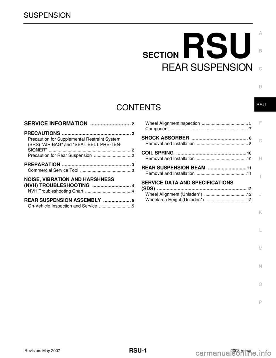
RSU-1
SUSPENSION
C
D
F
G
H
I
J
K
L
M
SECTION RSU
A
B
RSU
N
O
PCONTENTS
REAR SUSPENSION
SERVICE INFORMATION ............................2
PRECAUTIONS ...................................................2
Precaution for Supplemental Restraint System
(SRS) "AIR BAG" and "SEAT BELT PRE-TEN-
SIONER" ...................................................................
2
Precaution for Rear Suspension ...............................2
PREPARATION ...................................................3
Commercial Service Tool ..........................................3
NOISE, VIBRATION AND HARSHNESS
(NVH) TROUBLESHOOTING .............................
4
NVH Troubleshooting Chart ......................................4
REAR SUSPENSION ASSEMBLY .....................5
On-Vehicle Inspection and Service ...........................5
Wheel AlignmentInspection ......................................5
Component ...............................................................7
SHOCK ABSORBER .........................................8
Removal and Installation ..........................................8
COIL SPRING ...................................................10
Removal and Installation .........................................10
REAR SUSPENSION BEAM ............................11
Removal and Installation .........................................11
SERVICE DATA AND SPECIFICATIONS
(SDS) .................................................................
12
Wheel Alignment (Unladen*) ...................................12
Wheelarch Height (Unladen*) ..................................12
Page 2563 of 2771
RSU-4
< SERVICE INFORMATION >
NOISE, VIBRATION AND HARSHNESS (NVH) TROUBLESHOOTING
NOISE, VIBRATION AND HARSHNESS (NVH) TROUBLESHOOTING
NVH Troubleshooting ChartINFOID:0000000001703735
Use chart below to help you find the cause of the symptom. If necessary, repair or replace these parts.
×: ApplicableReference page
RSU-7RSU-8RSU-8RSU-8RSU-10RSU-7RSU-5RSU-4WT-4WT-4BR-4PS-5
Possible cause and SUSPECTED PARTS
Improper installation, looseness
Shock absorber deformation, damage or deflection
Bushing or mounting deterioration
Parts interference
Spring fatigue
Suspension looseness
Incorrect wheel alignment
REAR AXLE
TIRES
ROAD WHEEL
BRAKES
STEERING
SymptomNoise×××××× ×××××
Shake×××× × ×××××
Vibration××××× ×× ×
Shimmy×××× ××××××
Judder ××× ×××××
Poor quality ride or handling××××× ××××
Page 2564 of 2771

REAR SUSPENSION ASSEMBLY
RSU-5
< SERVICE INFORMATION >
C
D
F
G
H
I
J
K
L
MA
B
RSU
N
O
P
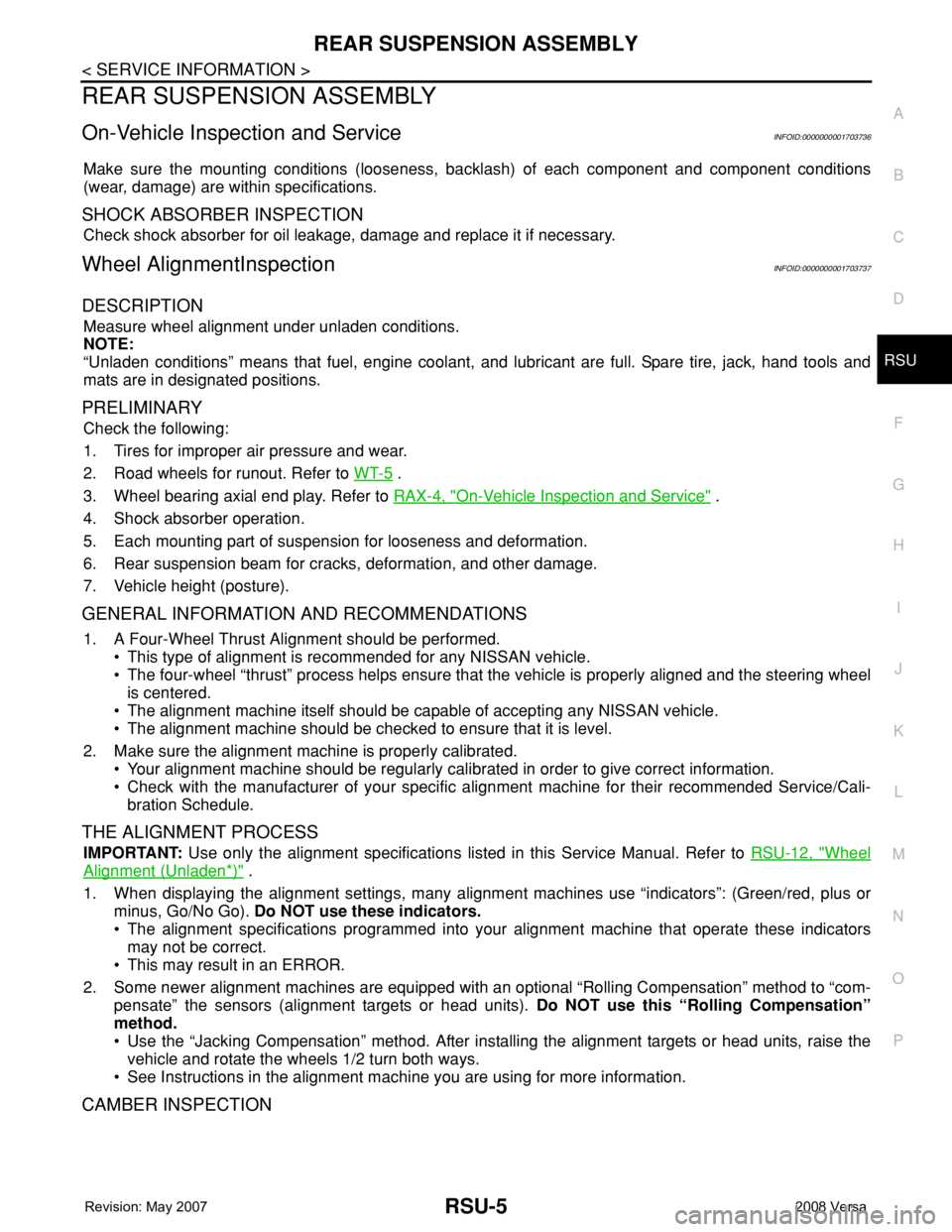
REAR SUSPENSION ASSEMBLY
On-Vehicle Inspection and ServiceINFOID:0000000001703736
Make sure the mounting conditions (looseness, backlash) of each component and component conditions
(wear, damage) are within specifications.
SHOCK ABSORBER INSPECTION
Check shock absorber for oil leakage, damage and replace it if necessary.
Wheel AlignmentInspectionINFOID:0000000001703737
DESCRIPTION
Measure wheel alignment under unladen conditions.
NOTE:
“Unladen conditions” means that fuel, engine coolant, and lubricant are full. Spare tire, jack, hand tools and
mats are in designated positions.
PRELIMINARY
Check the following:
1. Tires for improper air pressure and wear.
2. Road wheels for runout. Refer to WT-5
.
3. Wheel bearing axial end play. Refer to RAX-4, "
On-Vehicle Inspection and Service" .
4. Shock absorber operation.
5. Each mounting part of suspension for looseness and deformation.
6. Rear suspension beam for cracks, deformation, and other damage.
7. Vehicle height (posture).
GENERAL INFORMATION AND RECOMMENDATIONS
1. A Four-Wheel Thrust Alignment should be performed.
• This type of alignment is recommended for any NISSAN vehicle.
• The four-wheel “thrust” process helps ensure that the vehicle is properly aligned and the steering wheel
is centered.
• The alignment machine itself should be capable of accepting any NISSAN vehicle.
• The alignment machine should be checked to ensure that it is level.
2. Make sure the alignment machine is properly calibrated.
• Your alignment machine should be regularly calibrated in order to give correct information.
• Check with the manufacturer of your specific alignment machine for their recommended Service/Cali-
bration Schedule.
THE ALIGNMENT PROCESS
IMPORTANT: Use only the alignment specifications listed in this Service Manual. Refer to RSU-12, "Wheel
Alignment (Unladen*)" .
1. When displaying the alignment settings, many alignment machines use “indicators”: (Green/red, plus or
minus, Go/No Go). Do NOT use these indicators.
• The alignment specifications programmed into your alignment machine that operate these indicators
may not be correct.
• This may result in an ERROR.
2. Some newer alignment machines are equipped with an optional “Rolling Compensation” method to “com-
pensate” the sensors (alignment targets or head units). Do NOT use this “Rolling Compensation”
method.
• Use the “Jacking Compensation” method. After installing the alignment targets or head units, raise the
vehicle and rotate the wheels 1/2 turn both ways.
• See Instructions in the alignment machine you are using for more information.
CAMBER INSPECTION