2008 NISSAN LATIO warning
[x] Cancel search: warningPage 1073 of 2771
DI-52
< SERVICE INFORMATION >
WARNING CHIME
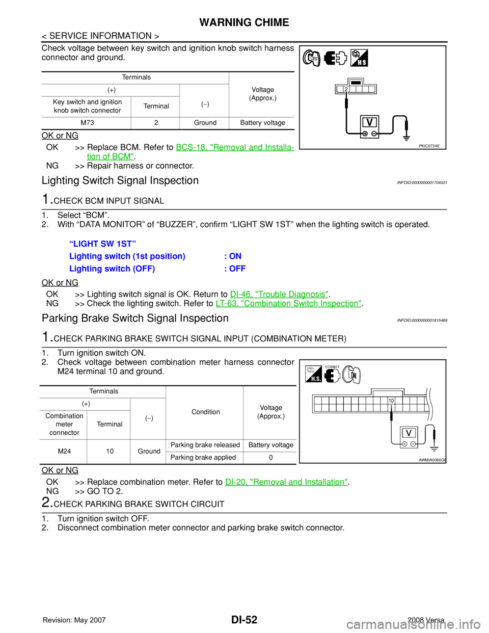
Check voltage between key switch and ignition knob switch harness
connector and ground.
OK or NG
OK >> Replace BCM. Refer to BCS-18, "Removal and Installa-
tion of BCM".
NG >> Repair harness or connector.
Lighting Switch Signal InspectionINFOID:0000000001704531
1.CHECK BCM INPUT SIGNAL
1. Select “BCM”.
2. With “DATA MONITOR” of “BUZZER”, confirm “LIGHT SW 1ST” when the lighting switch is operated.
OK or NG
OK >> Lighting switch signal is OK. Return to DI-46, "Trouble Diagnosis".
NG >> Check the lighting switch. Refer to LT-63, "
Combination Switch Inspection".
Parking Brake Switch Signal InspectionINFOID:0000000001815489
1.CHECK PARKING BRAKE SWITCH SIGNAL INPUT (COMBINATION METER)
1. Turn ignition switch ON.
2. Check voltage between combination meter harness connector
M24 terminal 10 and ground.
OK or NG
OK >> Replace combination meter. Refer to DI-20, "Removal and Installation".
NG >> GO TO 2.
2.CHECK PARKING BRAKE SWITCH CIRCUIT
1. Turn ignition switch OFF.
2. Disconnect combination meter connector and parking brake switch connector.
Te r m i n a l s
Vo l ta g e
(Approx.) (+)
(−) Key switch and ignition
knob switch connector Te r m i n a l
M73 2 Ground Battery voltage
PKIC0724E
“LIGHT SW 1ST”
Lighting switch (1st position) : ON
Lighting switch (OFF) : OFF
Te r m i n a l s
ConditionVoltag e
(Approx.) (+)
(−) Combination
meter
connectorTe r m i n a l
M24 10 GroundParking brake released Battery voltage
Parking brake applied 0
AWMIA0066GB
Page 1074 of 2771
WARNING CHIME
DI-53
< SERVICE INFORMATION >
C
D
E
F
G
H
I
J
L
MA
B
DI
N
O
P
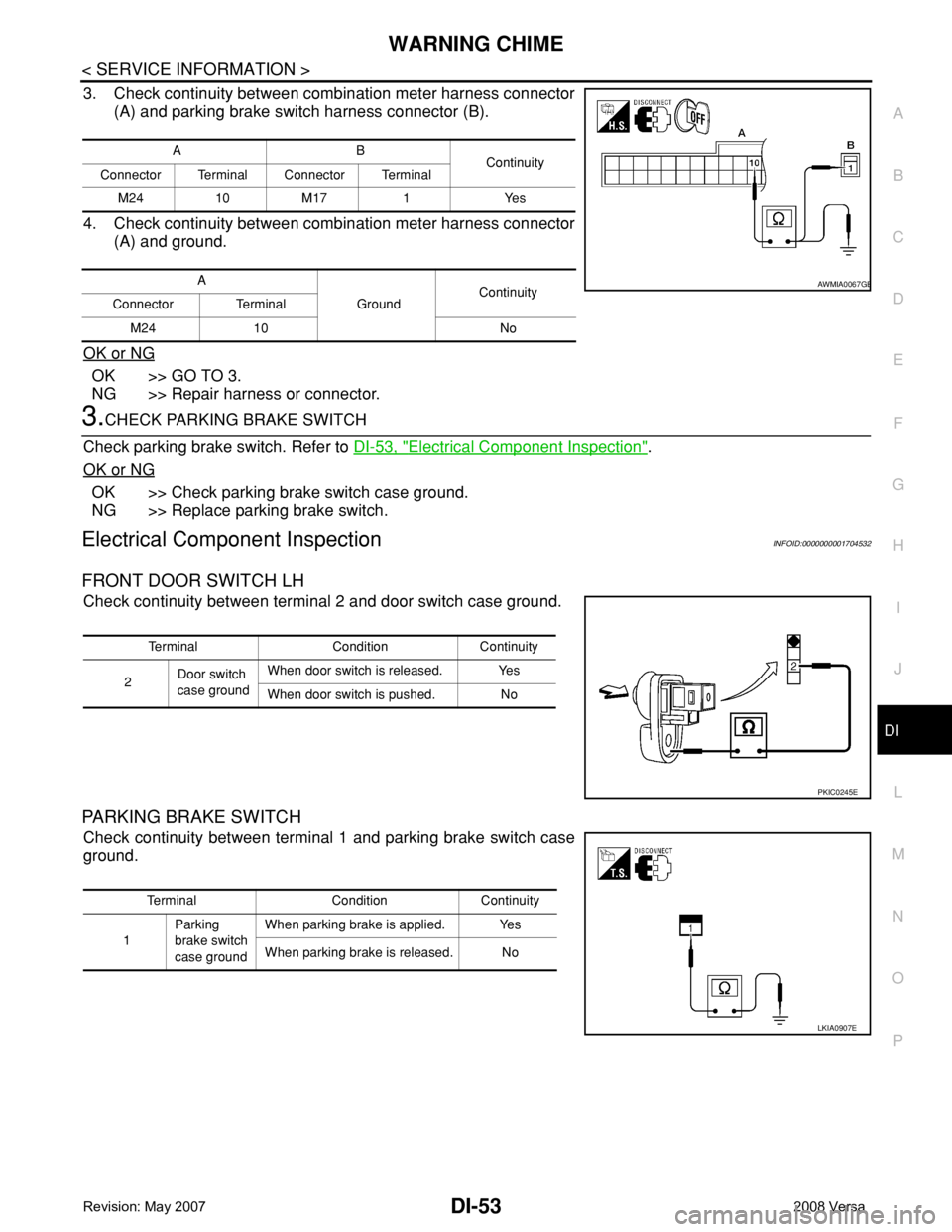
3. Check continuity between combination meter harness connector
(A) and parking brake switch harness connector (B).
4. Check continuity between combination meter harness connector
(A) and ground.
OK or NG
OK >> GO TO 3.
NG >> Repair harness or connector.
3.CHECK PARKING BRAKE SWITCH
Check parking brake switch. Refer to DI-53, "
Electrical Component Inspection".
OK or NG
OK >> Check parking brake switch case ground.
NG >> Replace parking brake switch.
Electrical Component InspectionINFOID:0000000001704532
FRONT DOOR SWITCH LH
Check continuity between terminal 2 and door switch case ground.
PARKING BRAKE SWITCH
Check continuity between terminal 1 and parking brake switch case
ground.
AB
Continuity
Connector Terminal Connector Terminal
M2410M17 1 Yes
A
GroundContinuity
Connector Terminal
M24 10 No
AWMIA0067GB
Terminal Condition Continuity
2Door switch
case groundWhen door switch is released. Yes
When door switch is pushed. No
PKIC0245E
Terminal Condition Continuity
1Parking
brake switch
case groundWhen parking brake is applied. Yes
When parking brake is released. No
LKIA0907E
Page 1090 of 2771
EC-16
< SERVICE INFORMATION >
PRECAUTIONS
PRECAUTIONS
Precaution for Supplemental Restraint System (SRS) "AIR BAG" and "SEAT BELT
PRE-TENSIONER"
INFOID:0000000001702548
The Supplemental Restraint System such as “AIR BAG” and “SEAT BELT PRE-TENSIONER”, used along
with a front seat belt, helps to reduce the risk or severity of injury to the driver and front passenger for certain
types of collision. This system includes seat belt switch inputs and dual stage front air bag modules. The SRS
system uses the seat belt switches to determine the front air bag deployment, and may only deploy one front
air bag, depending on the severity of a collision and whether the front occupants are belted or unbelted.
Information necessary to service the system safely is included in the SRS and SB section of this Service Man-
ual.
WARNING:
• To avoid rendering the SRS inoperative, which could increase the risk of personal injury or death in
the event of a collision which would result in air bag inflation, all maintenance must be performed by
an authorized NISSAN/INFINITI dealer.
• Improper maintenance, including incorrect removal and installation of the SRS, can lead to personal
injury caused by unintentional activation of the system. For removal of Spiral Cable and Air Bag
Module, see the SRS section.
• Do not use electrical test equipment on any circuit related to the SRS unless instructed to in this
Service Manual. SRS wiring harnesses can be identified by yellow and/or orange harnesses or har-
ness connectors.
Precaution for Procedure without Cowl Top CoverINFOID:0000000001702549
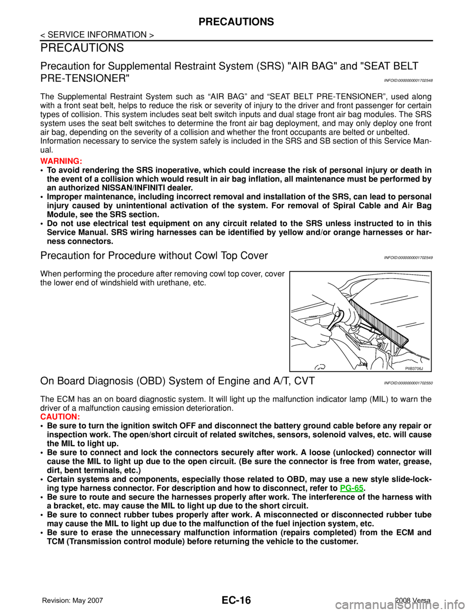
When performing the procedure after removing cowl top cover, cover
the lower end of windshield with urethane, etc.
On Board Diagnosis (OBD) System of Engine and A/T, CVTINFOID:0000000001702550
The ECM has an on board diagnostic system. It will light up the malfunction indicator lamp (MIL) to warn the
driver of a malfunction causing emission deterioration.
CAUTION:
• Be sure to turn the ignition switch OFF and disconnect the battery ground cable before any repair or
inspection work. The open/short circuit of related switches, sensors, solenoid valves, etc. will cause
the MIL to light up.
• Be sure to connect and lock the connectors securely after work. A loose (unlocked) connector will
cause the MIL to light up due to the open circuit. (Be sure the connector is free from water, grease,
dirt, bent terminals, etc.)
• Certain systems and components, especially those related to OBD, may use a new style slide-lock-
ing type harness connector. For description and how to disconnect, refer to PG-65
.
• Be sure to route and secure the harnesses properly after work. The interference of the harness with
a bracket, etc. may cause the MIL to light up due to the short circuit.
• Be sure to connect rubber tubes properly after work. A misconnected or disconnected rubber tube
may cause the MIL to light up due to the malfunction of the fuel injection system, etc.
• Be sure to erase the unnecessary malfunction information (repairs completed) from the ECM and
TCM (Transmission control module) before returning the vehicle to the customer.
PIIB3706J
Page 1112 of 2771
EC-38
< SERVICE INFORMATION >
ON BOARD REFUELING VAPOR RECOVERY (ORVR)
ON BOARD REFUELING VAPOR RECOVERY (ORVR)
System DescriptionINFOID:0000000001702567
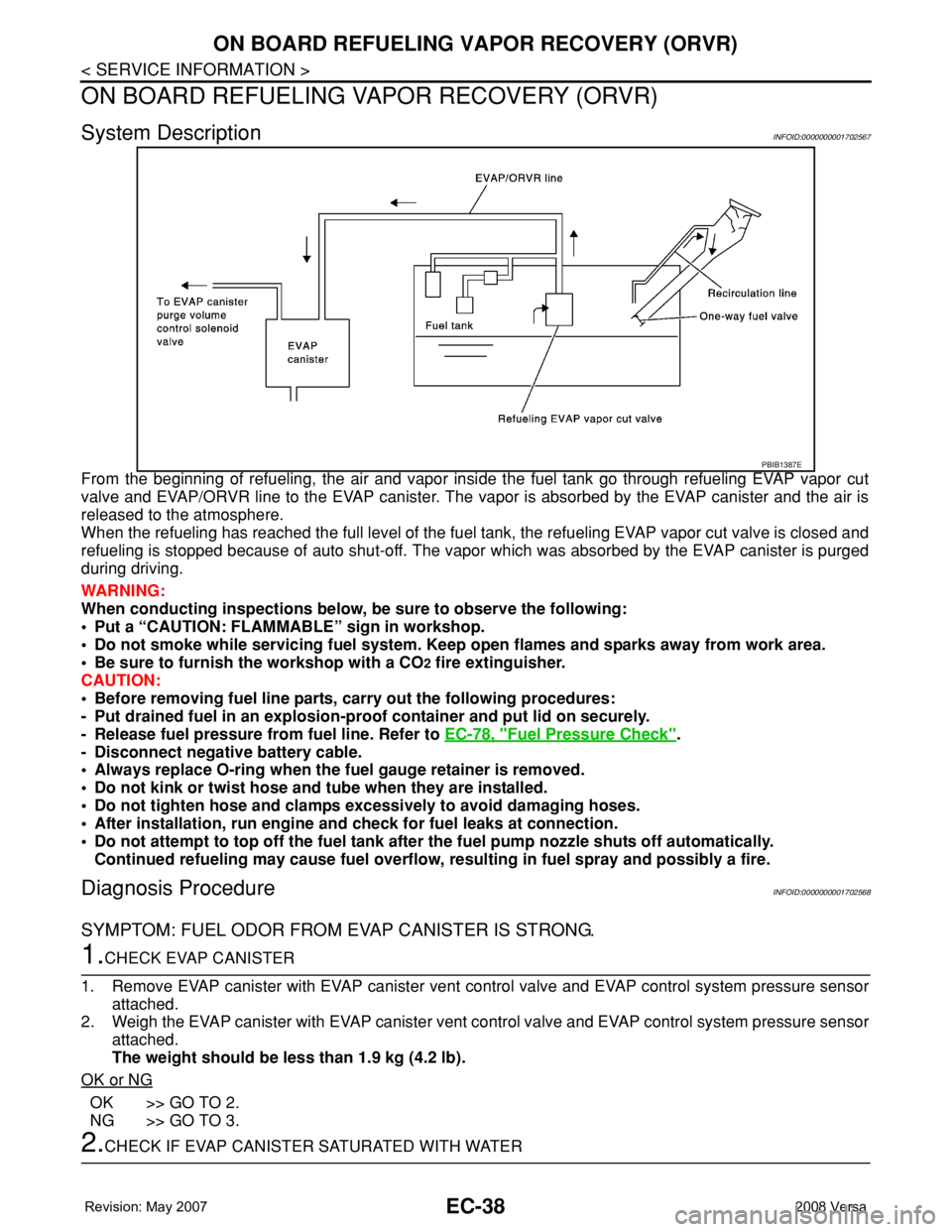
From the beginning of refueling, the air and vapor inside the fuel tank go through refueling EVAP vapor cut
valve and EVAP/ORVR line to the EVAP canister. The vapor is absorbed by the EVAP canister and the air is
released to the atmosphere.
When the refueling has reached the full level of the fuel tank, the refueling EVAP vapor cut valve is closed and
refueling is stopped because of auto shut-off. The vapor which was absorbed by the EVAP canister is purged
during driving.
WARNING:
When conducting inspections below, be sure to observe the following:
• Put a “CAUTION: FLAMMABLE” sign in workshop.
• Do not smoke while servicing fuel system. Keep open flames and sparks away from work area.
• Be sure to furnish the workshop with a CO
2 fire extinguisher.
CAUTION:
• Before removing fuel line parts, carry out the following procedures:
- Put drained fuel in an explosion-proof container and put lid on securely.
- Release fuel pressure from fuel line. Refer to EC-78, "
Fuel Pressure Check".
- Disconnect negative battery cable.
• Always replace O-ring when the fuel gauge retainer is removed.
• Do not kink or twist hose and tube when they are installed.
• Do not tighten hose and clamps excessively to avoid damaging hoses.
• After installation, run engine and check for fuel leaks at connection.
• Do not attempt to top off the fuel tank after the fuel pump nozzle shuts off automatically.
Continued refueling may cause fuel overflow, resulting in fuel spray and possibly a fire.
Diagnosis ProcedureINFOID:0000000001702568
SYMPTOM: FUEL ODOR FROM EVAP CANISTER IS STRONG.
1.CHECK EVAP CANISTER
1. Remove EVAP canister with EVAP canister vent control valve and EVAP control system pressure sensor
attached.
2. Weigh the EVAP canister with EVAP canister vent control valve and EVAP control system pressure sensor
attached.
The weight should be less than 1.9 kg (4.2 lb).
OK or NG
OK >> GO TO 2.
NG >> GO TO 3.
2.CHECK IF EVAP CANISTER SATURATED WITH WATER
PBIB1387E
Page 1135 of 2771
ON BOARD DIAGNOSTIC (OBD) SYSTEM
EC-61
< SERVICE INFORMATION >
C
D
E
F
G
H
I
J
K
L
MA
EC
N
P O
When there is an open circuit on MIL circuit, the ECM cannot warn the driver by MIL lighting up when there is
malfunction on engine control system.
Therefore, when electrical controlled throttle and part of ECM related diagnoses are continuously detected as
NG for 5 trips, ECM warns the driver that engine control system malfunctions and MIL circuit is open by means
of operating fail-safe function.
The fail-safe function also operates when above diagnoses except MIL circuit are detected, and demands the
driver to repair the malfunction.
MIL Flashing Without DTC
When any SRT codes are not set, MIL may flash without DTC. For the details, refer to EC-47, "Emission-
related Diagnostic Information".
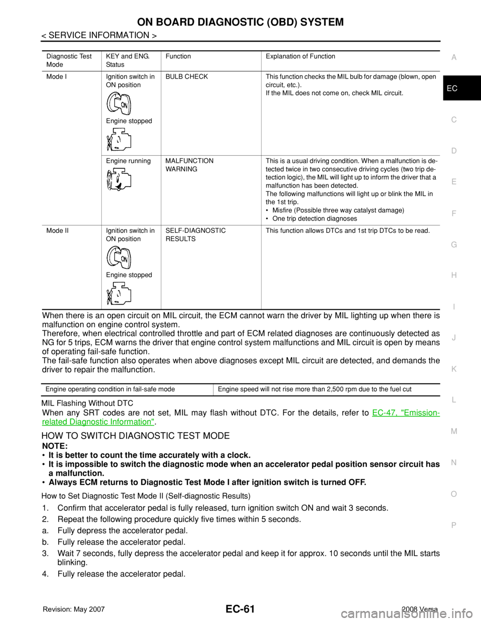
HOW TO SWITCH DIAGNOSTIC TEST MODE
NOTE:
•It is better to count the time accurately with a clock.
•It is impossible to switch the diagnostic mode when an accelerator pedal position sensor circuit has
a malfunction.
•Always ECM returns to Diagnostic Test Mode I after ignition switch is turned OFF.
How to Set Diagnostic Test Mode II (Self-diagnostic Results)
1. Confirm that accelerator pedal is fully released, turn ignition switch ON and wait 3 seconds.
2. Repeat the following procedure quickly five times within 5 seconds.
a. Fully depress the accelerator pedal.
b. Fully release the accelerator pedal.
3. Wait 7 seconds, fully depress the accelerator pedal and keep it for approx. 10 seconds until the MIL starts
blinking.
4. Fully release the accelerator pedal.
Diagnostic Test
ModeKEY and ENG.
Sta tusFunction Explanation of Function
Mode I Ignition switch in
ON position
Engine stoppedBULB CHECK This function checks the MIL bulb for damage (blown, open
circuit, etc.).
If the MIL does not come on, check MIL circuit.
Engine running MALFUNCTION
WARNINGThis is a usual driving condition. When a malfunction is de-
tected twice in two consecutive driving cycles (two trip de-
tection logic), the MIL will light up to inform the driver that a
malfunction has been detected.
The following malfunctions will light up or blink the MIL in
the 1st trip.
• Misfire (Possible three way catalyst damage)
• One trip detection diagnoses
Mode II Ignition switch in
ON position
Engine stoppedSELF-DIAGNOSTIC
RESULTSThis function allows DTCs and 1st trip DTCs to be read.
Engine operating condition in fail-safe mode Engine speed will not rise more than 2,500 rpm due to the fuel cut
Page 1136 of 2771
EC-62
< SERVICE INFORMATION >
ON BOARD DIAGNOSTIC (OBD) SYSTEM
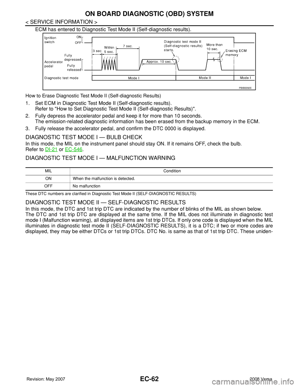
ECM has entered to Diagnostic Test Mode II (Self-diagnostic results).
How to Erase Diagnostic Test Mode II (Self-diagnostic Results)
1. Set ECM in Diagnostic Test Mode II (Self-diagnostic results).
Refer to "How to Set Diagnostic Test Mode II (Self-diagnostic Results)".
2. Fully depress the accelerator pedal and keep it for more than 10 seconds.
The emission-related diagnostic information has been erased from the backup memory in the ECM.
3. Fully release the accelerator pedal, and confirm the DTC 0000 is displayed.
DIAGNOSTIC TEST MODE I — BULB CHECK
In this mode, the MIL on the instrument panel should stay ON. If it remains OFF, check the bulb.
Refer to DI-21
or EC-546.
DIAGNOSTIC TEST MODE I — MALFUNCTION WARNING
These DTC numbers are clarified in Diagnostic Test Mode II (SELF-DIAGNOSTIC RESULTS)
DIAGNOSTIC TEST MODE II — SELF-DIAGNOSTIC RESULTS
In this mode, the DTC and 1st trip DTC are indicated by the number of blinks of the MIL as shown below.
The DTC and 1st trip DTC are displayed at the same time. If the MIL does not illuminate in diagnostic test
mode I (Malfunction warning), all displayed items are 1st trip DTCs. If only one code is displayed when the MIL
illuminates in diagnostic test mode II (SELF-DIAGNOSTIC RESULTS), it is a DTC; if two or more codes are
displayed, they may be either DTCs or 1st trip DTCs. DTC No. is same as that of 1st trip DTC. These uniden-
PBIB0092E
MIL Condition
ON When the malfunction is detected.
OFF No malfunction
Page 1223 of 2771
DTC P0011 IVT CONTROL
EC-149
< SERVICE INFORMATION >
C
D
E
F
G
H
I
J
K
L
MA
EC
N
P O7. If 1st trip DTC is detected, go to EC-149, "Diagnosis Procedure".
WITH GST
Follow the procedure “WITH CONSULT-II” above.
Diagnosis ProcedureINFOID:0000000001702621
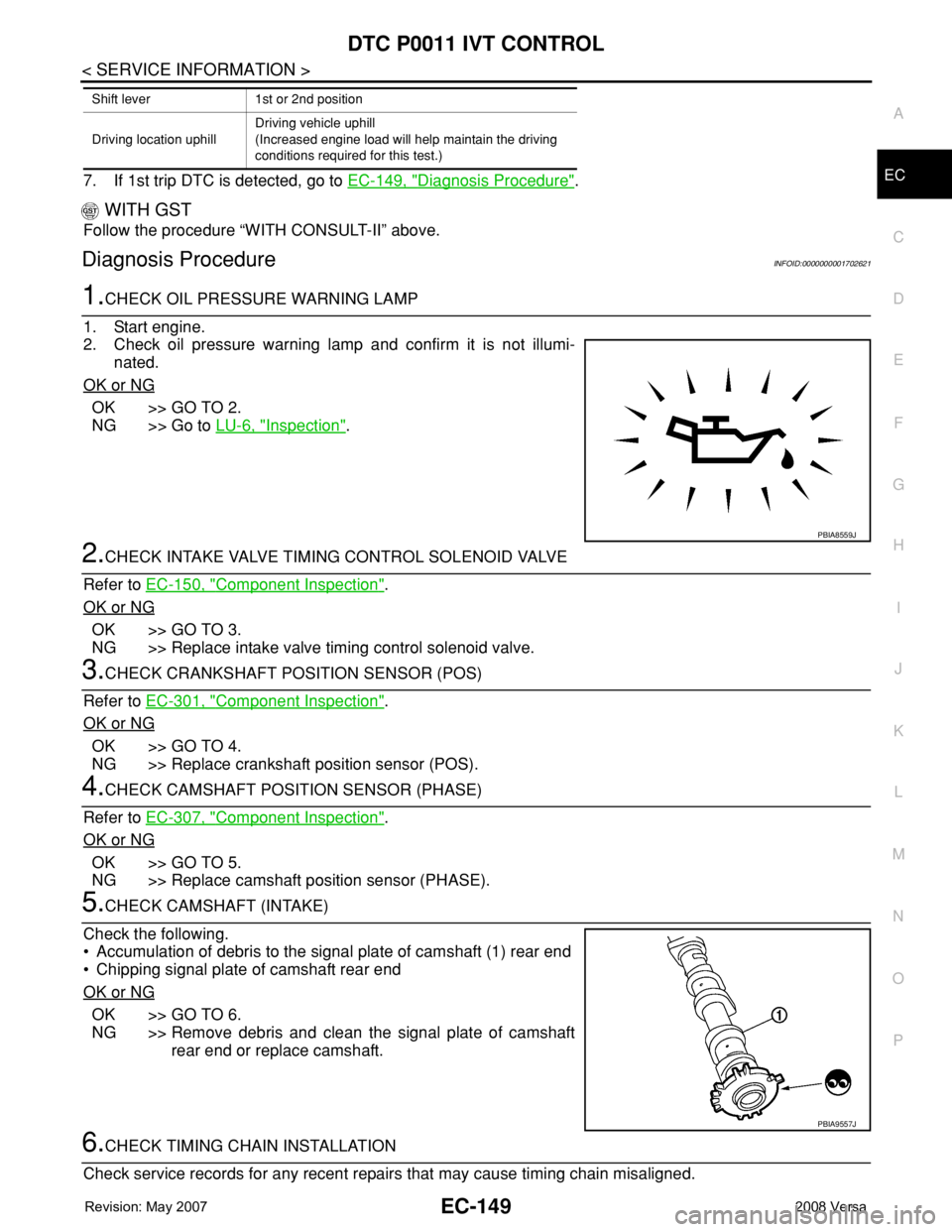
1.CHECK OIL PRESSURE WARNING LAMP
1. Start engine.
2. Check oil pressure warning lamp and confirm it is not illumi-
nated.
OK or NG
OK >> GO TO 2.
NG >> Go to LU-6, "
Inspection".
2.CHECK INTAKE VALVE TIMING CONTROL SOLENOID VALVE
Refer to EC-150, "
Component Inspection".
OK or NG
OK >> GO TO 3.
NG >> Replace intake valve timing control solenoid valve.
3.CHECK CRANKSHAFT POSITION SENSOR (POS)
Refer to EC-301, "
Component Inspection".
OK or NG
OK >> GO TO 4.
NG >> Replace crankshaft position sensor (POS).
4.CHECK CAMSHAFT POSITION SENSOR (PHASE)
Refer to EC-307, "
Component Inspection".
OK or NG
OK >> GO TO 5.
NG >> Replace camshaft position sensor (PHASE).
5.CHECK CAMSHAFT (INTAKE)
Check the following.
• Accumulation of debris to the signal plate of camshaft (1) rear end
• Chipping signal plate of camshaft rear end
OK or NG
OK >> GO TO 6.
NG >> Remove debris and clean the signal plate of camshaft
rear end or replace camshaft.
6.CHECK TIMING CHAIN INSTALLATION
Check service records for any recent repairs that may cause timing chain misaligned.
Shift lever 1st or 2nd position
Driving location uphillDriving vehicle uphill
(Increased engine load will help maintain the driving
conditions required for this test.)
PBIA8559J
PBIA9557J
Page 1461 of 2771
DTC P0461 FUEL LEVEL SENSOR
EC-387
< SERVICE INFORMATION >
C
D
E
F
G
H
I
J
K
L
MA
EC
N
P O
DTC P0461 FUEL LEVEL SENSOR
Component DescriptionINFOID:0000000001702890
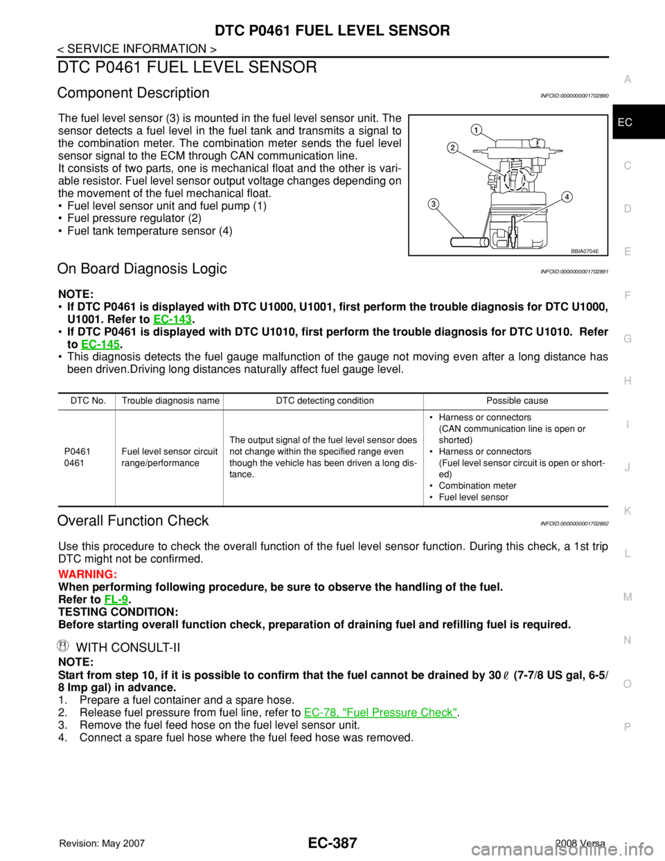
The fuel level sensor (3) is mounted in the fuel level sensor unit. The
sensor detects a fuel level in the fuel tank and transmits a signal to
the combination meter. The combination meter sends the fuel level
sensor signal to the ECM through CAN communication line.
It consists of two parts, one is mechanical float and the other is vari-
able resistor. Fuel level sensor output voltage changes depending on
the movement of the fuel mechanical float.
• Fuel level sensor unit and fuel pump (1)
• Fuel pressure regulator (2)
• Fuel tank temperature sensor (4)
On Board Diagnosis LogicINFOID:0000000001702891
NOTE:
•If DTC P0461 is displayed with DTC U1000, U1001, first perform the trouble diagnosis for DTC U1000,
U1001. Refer to EC-143
.
•If DTC P0461 is displayed with DTC U1010, first perform the trouble diagnosis for DTC U1010. Refer
to EC-145
.
• This diagnosis detects the fuel gauge malfunction of the gauge not moving even after a long distance has
been driven.Driving long distances naturally affect fuel gauge level.
Overall Function CheckINFOID:0000000001702892
Use this procedure to check the overall function of the fuel level sensor function. During this check, a 1st trip
DTC might not be confirmed.
WARNING:
When performing following procedure, be sure to observe the handling of the fuel.
Refer to FL-9
.
TESTING CONDITION:
Before starting overall function check, preparation of draining fuel and refilling fuel is required.
WITH CONSULT-II
NOTE:
Start from step 10, if it is possible to confirm that the fuel cannot be drained by 30 (7-7/8 US gal, 6-5/
8 Imp gal) in advance.
1. Prepare a fuel container and a spare hose.
2. Release fuel pressure from fuel line, refer to EC-78, "
Fuel Pressure Check".
3. Remove the fuel feed hose on the fuel level sensor unit.
4. Connect a spare fuel hose where the fuel feed hose was removed.
BBIA0704E
DTC No. Trouble diagnosis name DTC detecting condition Possible cause
P0461
0461Fuel level sensor circuit
range/performanceThe output signal of the fuel level sensor does
not change within the specified range even
though the vehicle has been driven a long dis-
tance.• Harness or connectors
(CAN communication line is open or
shorted)
• Harness or connectors
(Fuel level sensor circuit is open or short-
ed)
• Combination meter
• Fuel level sensor