Page 955 of 2771
CVT-116
< SERVICE INFORMATION >
DTC P0845 TRANSMISSION FLUID PRESSURE SENSOR B CIRCUIT (PRI
PRESSURE SENSOR)
Wiring Diagram - CVT - PRIPS
INFOID:0000000001703591
CM TERMINALS AND REFERENCE VALUES
Refer to CVT-45, "TCM Terminal and Reference Value".
BCWA0678E
Page 959 of 2771

CVT-120
< SERVICE INFORMATION >
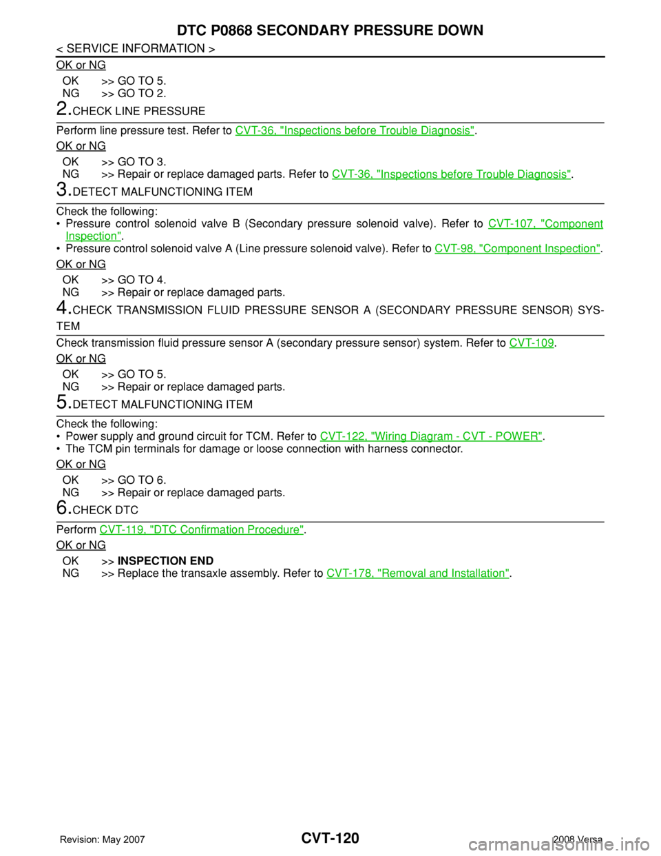
DTC P0868 SECONDARY PRESSURE DOWN
OK or NG
OK >> GO TO 5.
NG >> GO TO 2.
2.CHECK LINE PRESSURE
Perform line pressure test. Refer to CVT-36, "
Inspections before Trouble Diagnosis".
OK or NG
OK >> GO TO 3.
NG >> Repair or replace damaged parts. Refer to CVT-36, "
Inspections before Trouble Diagnosis".
3.DETECT MALFUNCTIONING ITEM
Check the following:
• Pressure control solenoid valve B (Secondary pressure solenoid valve). Refer to CVT-107, "
Component
Inspection".
• Pressure control solenoid valve A (Line pressure solenoid valve). Refer to CVT-98, "
Component Inspection".
OK or NG
OK >> GO TO 4.
NG >> Repair or replace damaged parts.
4.CHECK TRANSMISSION FLUID PRESSURE SENSOR A (SECONDARY PRESSURE SENSOR) SYS-
TEM
Check transmission fluid pressure sensor A (secondary pressure sensor) system. Refer to CVT-109
.
OK or NG
OK >> GO TO 5.
NG >> Repair or replace damaged parts.
5.DETECT MALFUNCTIONING ITEM
Check the following:
• Power supply and ground circuit for TCM. Refer to CVT-122, "
Wiring Diagram - CVT - POWER".
• The TCM pin terminals for damage or loose connection with harness connector.
OK or NG
OK >> GO TO 6.
NG >> Repair or replace damaged parts.
6.CHECK DTC
Perform CVT-119, "
DTC Confirmation Procedure".
OK or NG
OK >>INSPECTION END
NG >> Replace the transaxle assembly. Refer to CVT-178, "
Removal and Installation".
Page 961 of 2771
CVT-122
< SERVICE INFORMATION >
DTC P1701 TRANSMISSION CONTROL MODULE (POWER SUPPLY)
Wiring Diagram - CVT - POWER
INFOID:0000000001703603
TCM TERMINALS AND REFERENCE VALUES
Refer to CVT-45, "TCM Terminal and Reference Value" .
BCWA0679E
Page 972 of 2771
DTC P1740 LOCK-UP SELECT SOLENOID VALVE CIRCUIT
CVT-133
< SERVICE INFORMATION >
D
E
F
G
H
I
J
K
L
MA
B
CVT
N
O
P
Wiring Diagram - CVT - L/USSVINFOID:0000000001703632
TCM TERMINALS AND REFERENCE VALUES
Refer to CVT-45, "TCM Terminal and Reference Value".
BCWA0680E
Page 977 of 2771
CVT-138
< SERVICE INFORMATION >
DTC P1777 STEP MOTOR - CIRCUIT
Wiring Diagram - CVT - STM
INFOID:0000000001703645
TCM TERMINALS AND REFERENCE VALUES
Refer to CVT-45, "TCM Terminal and Reference Value".
BCWA0681E
Page 983 of 2771
CVT-144
< SERVICE INFORMATION >
OVERDRIVE CONTROL SWITCH
Wiring Diagram - CVT - ODSW
INFOID:0000000001703656
TCM TERMINALS AND REFERENCE VALUES
Refer to CVT-45, "TCM Terminal and Reference Value".
Diagnosis ProcedureINFOID:0000000001703657
1.CHECK CAN COMMUNICATION LINE
BCWA0686E
Page 988 of 2771
TROUBLE DIAGNOSIS FOR SYMPTOMS
CVT-149
< SERVICE INFORMATION >
D
E
F
G
H
I
J
K
L
MA
B
CVT
N
O
P
TROUBLE DIAGNOSIS FOR SYMPTOMS
Wiring Diagram - CVT - NONDTCINFOID:0000000001703662
BCWA0682E
Page 991 of 2771

CVT-152
< SERVICE INFORMATION >
TROUBLE DIAGNOSIS FOR SYMPTOMS
O/D OFF indicator lamp does not come on for about 2 seconds when turning ignition switch ON.
DIAGNOSTIC PROCEDURE
1.CHECK CAN COMMUNICATION LINE
Perform the self-diagnosis check. Refer to CVT-47, "
CONSULT-III Function (TRANSMISSION)".
Is any malfunction of the
“U1000 CAN COMM CIRCUIT” indicated in the results?
YES >> Check CAN communication line. Refer to CVT-56.
NO >> GO TO 2.
2.CHECK TCM POWER SOURCE
1. Turn ignition switch ON.
2. Check voltage between TCM connector terminals and ground.
Refer to CVT-122, "
Wiring Diagram - CVT - POWER".
OK or NG
OK >> GO TO 4.
NG >> GO TO 3.
3.DETECT MALFUNCTIONING ITEM
Check the following.
• Harness for short or open between ignition switch and TCM connector terminal 10, 19
Refer to CVT-122, "
Wiring Diagram - CVT - POWER".
• 10 A fuse (No.49, located in the IPDM E/R). Refer to CVT-122, "
Wiring Diagram - CVT - POWER".
• Ignition switch. Refer to PG-3
.
OK or NG
OK >> GO TO 4.
NG >> Repair or replace damaged parts.
4.CHECK TCM GROUND CIRCUIT
1. Turn ignition switch OFF.
2. Disconnect TCM connector.
3. Check continuity between TCM connector terminals and ground.
Refer to CVT-122, "
Wiring Diagram - CVT - POWER".
OK or NG
OK >> GO TO 5.
NG >> Repair open circuit or short to ground or short to power
in harness or connectors.
5.DETECT MALFUNCTIONING ITEM
Check the following.
• Harness and fuse for short or open between ignition switch and O/D OFF indicator lamp
Refer to PG-3
.
OK or NG
OK >> GO TO 6.
NG >> Repair or replace damaged parts.
6.CHECK SYMPTOM
NameConnec-
torTerminal Voltage (Approx.)
Power supply E3110 Battery voltage
19 Battery voltage
SCIA4737E
NameConnec-
torTerminal Continuity
Ground E3225
Ye s
48
SCIA2671E