Page 549 of 2771
INTELLIGENT KEY SYSTEM
BL-115
< SERVICE INFORMATION >
C
D
E
F
G
H
J
K
L
MA
B
BL
N
O
P
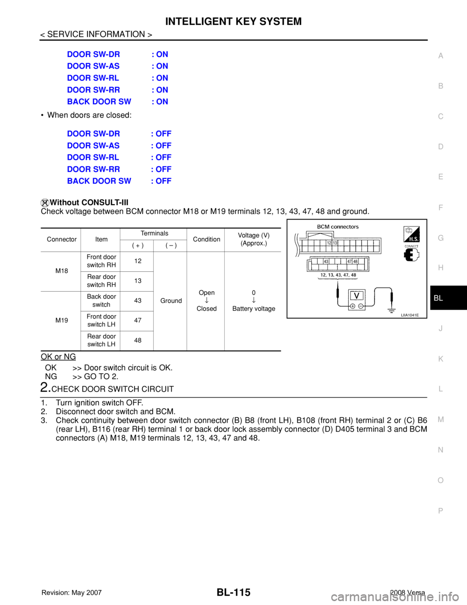
• When doors are closed:
Without CONSULT-III
Check voltage between BCM connector M18 or M19 terminals 12, 13, 43, 47, 48 and ground.
OK or NG
OK >> Door switch circuit is OK.
NG >> GO TO 2.
2.CHECK DOOR SWITCH CIRCUIT
1. Turn ignition switch OFF.
2. Disconnect door switch and BCM.
3. Check continuity between door switch connector (B) B8 (front LH), B108 (front RH) terminal 2 or (C) B6
(rear LH), B116 (rear RH) terminal 1 or back door lock assembly connector (D) D405 terminal 3 and BCM
connectors (A) M18, M19 terminals 12, 13, 43, 47 and 48. DOOR SW-DR : ON
DOOR SW-AS : ON
DOOR SW-RL : ON
DOOR SW-RR : ON
BACK DOOR SW : ON
DOOR SW-DR : OFF
DOOR SW-AS : OFF
DOOR SW-RL : OFF
DOOR SW-RR : OFF
BACK DOOR SW : OFF
Connector ItemTe r m i n a l s
ConditionVoltage (V)
(Approx.)
( + ) ( – )
M18Front door
switch RH12
GroundOpen
↓
Closed0
↓
Battery voltage Rear door
switch RH13
M19Back door
switch43
Front door
switch LH47
Rear door
switch LH48
LIIA1041E
Page 550 of 2771
BL-116
< SERVICE INFORMATION >
INTELLIGENT KEY SYSTEM
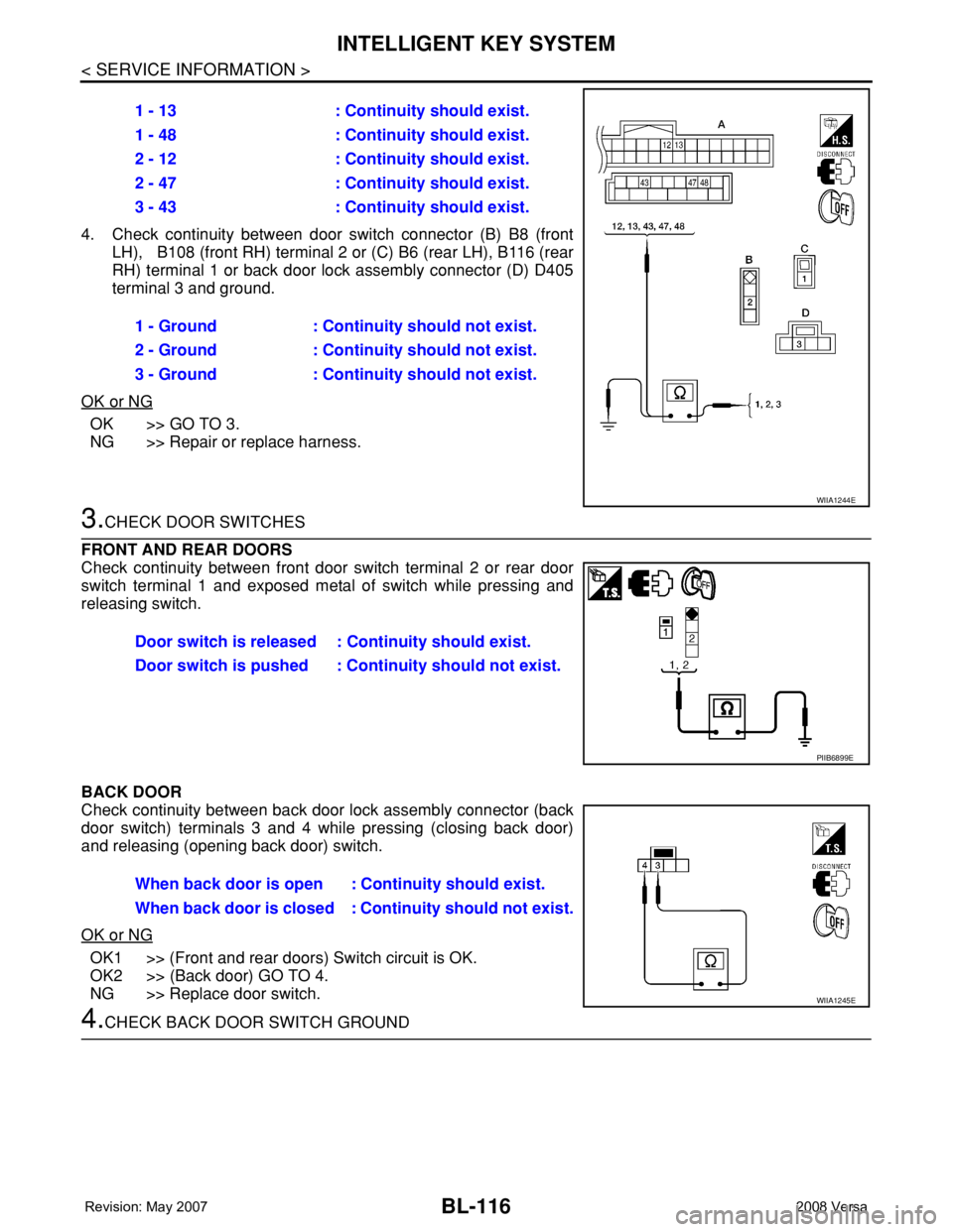
4. Check continuity between door switch connector (B) B8 (front
LH), B108 (front RH) terminal 2 or (C) B6 (rear LH), B116 (rear
RH) terminal 1 or back door lock assembly connector (D) D405
terminal 3 and ground.
OK or NG
OK >> GO TO 3.
NG >> Repair or replace harness.
3.CHECK DOOR SWITCHES
FRONT AND REAR DOORS
Check continuity between front door switch terminal 2 or rear door
switch terminal 1 and exposed metal of switch while pressing and
releasing switch.
BACK DOOR
Check continuity between back door lock assembly connector (back
door switch) terminals 3 and 4 while pressing (closing back door)
and releasing (opening back door) switch.
OK or NG
OK1 >> (Front and rear doors) Switch circuit is OK.
OK2 >> (Back door) GO TO 4.
NG >> Replace door switch.
4.CHECK BACK DOOR SWITCH GROUND1 - 13 : Continuity should exist.
1 - 48 : Continuity should exist.
2 - 12 : Continuity should exist.
2 - 47 : Continuity should exist.
3 - 43 : Continuity should exist.
1 - Ground : Continuity should not exist.
2 - Ground : Continuity should not exist.
3 - Ground : Continuity should not exist.
WIIA1244E
Door switch is released : Continuity should exist.
Door switch is pushed : Continuity should not exist.
PIIB6899E
When back door is open : Continuity should exist.
When back door is closed : Continuity should not exist.
WIIA1245E
Page 551 of 2771
INTELLIGENT KEY SYSTEM
BL-117
< SERVICE INFORMATION >
C
D
E
F
G
H
J
K
L
MA
B
BL
N
O
P
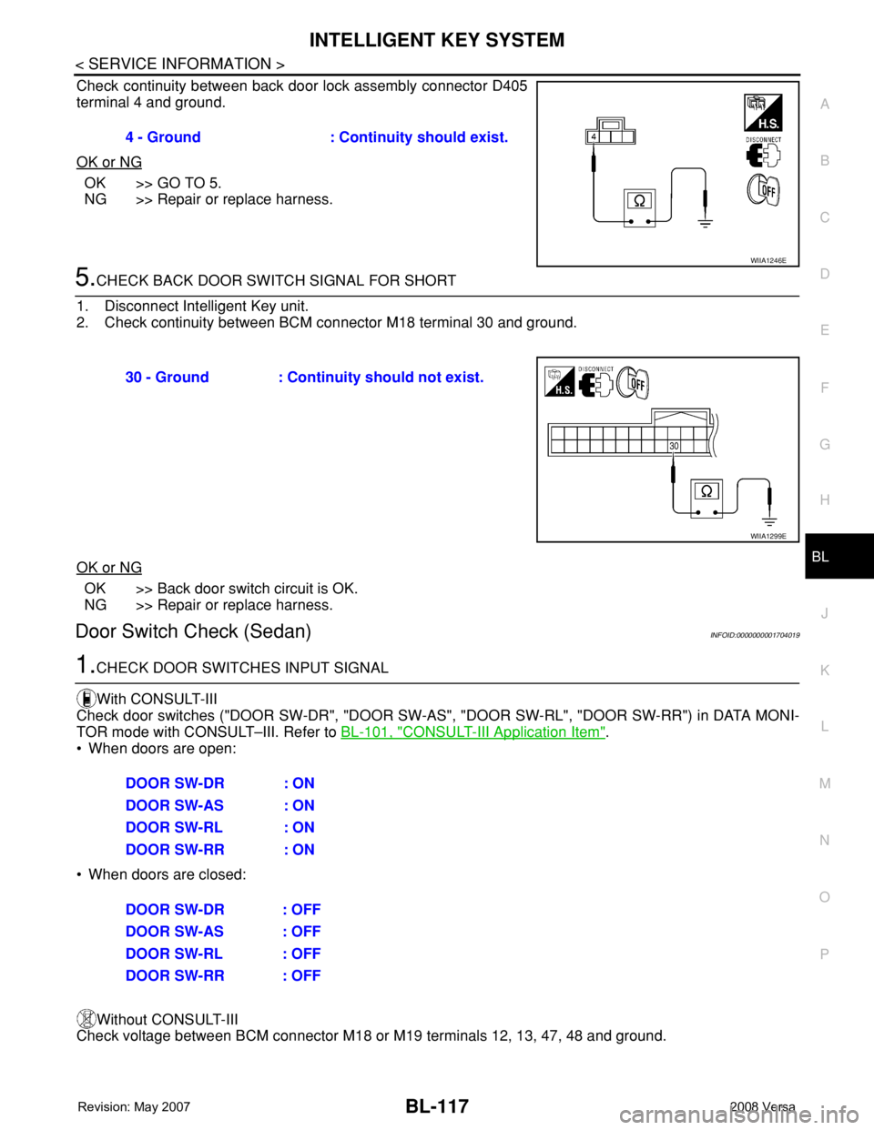
Check continuity between back door lock assembly connector D405
terminal 4 and ground.
OK or NG
OK >> GO TO 5.
NG >> Repair or replace harness.
5.CHECK BACK DOOR SWITCH SIGNAL FOR SHORT
1. Disconnect Intelligent Key unit.
2. Check continuity between BCM connector M18 terminal 30 and ground.
OK or NG
OK >> Back door switch circuit is OK.
NG >> Repair or replace harness.
Door Switch Check (Sedan)INFOID:0000000001704019
1.CHECK DOOR SWITCHES INPUT SIGNAL
With CONSULT-III
Check door switches ("DOOR SW-DR", "DOOR SW-AS", "DOOR SW-RL", "DOOR SW-RR") in DATA MONI-
TOR mode with CONSULT–III. Refer to BL-101, "
CONSULT-III Application Item".
• When doors are open:
• When doors are closed:
Without CONSULT-III
Check voltage between BCM connector M18 or M19 terminals 12, 13, 47, 48 and ground.4 - Ground : Continuity should exist.
WIIA1246E
30 - Ground : Continuity should not exist.
WIIA1299E
DOOR SW-DR : ON
DOOR SW-AS : ON
DOOR SW-RL : ON
DOOR SW-RR : ON
DOOR SW-DR : OFF
DOOR SW-AS : OFF
DOOR SW-RL : OFF
DOOR SW-RR : OFF
Page 558 of 2771
BL-124
< SERVICE INFORMATION >
INTELLIGENT KEY SYSTEM
OK or NG
OK >> Check the condition of harness and connector.
NG >> Replace Intelligent Key unit. Refer to BL-142, "
Removal
and Installation of Intelligent Key Unit".
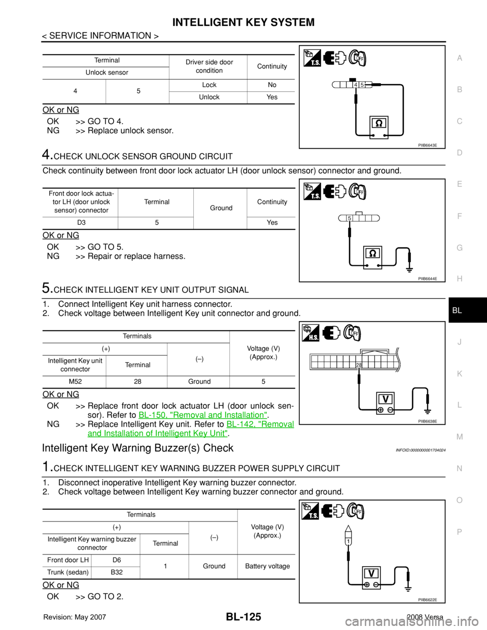
Unlock Sensor CheckINFOID:0000000001704023
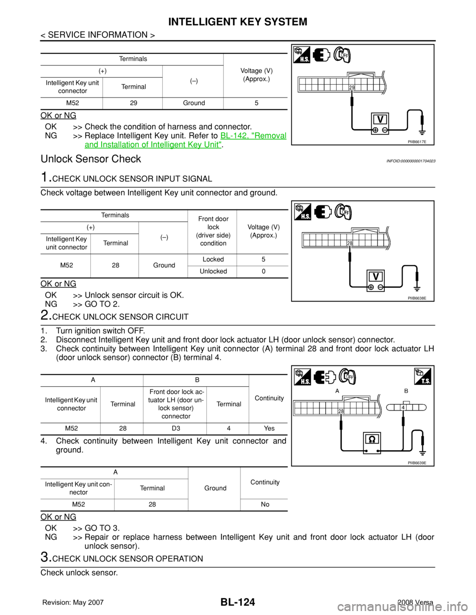
1.CHECK UNLOCK SENSOR INPUT SIGNAL
Check voltage between Intelligent Key unit connector and ground.
OK or NG
OK >> Unlock sensor circuit is OK.
NG >> GO TO 2.
2.CHECK UNLOCK SENSOR CIRCUIT
1. Turn ignition switch OFF.
2. Disconnect Intelligent Key unit and front door lock actuator LH (door unlock sensor) connector.
3. Check continuity between Intelligent Key unit connector (A) terminal 28 and front door lock actuator LH
(door unlock sensor) connector (B) terminal 4.
4. Check continuity between Intelligent Key unit connector and
ground.
OK or NG
OK >> GO TO 3.
NG >> Repair or replace harness between Intelligent Key unit and front door lock actuator LH (door
unlock sensor).
3.CHECK UNLOCK SENSOR OPERATION
Check unlock sensor.
Te r m i n a l s
Voltage (V)
(Approx.) (+)
(–)
Intelligent Key unit
connectorTe r m i n a l
M52 29 Ground 5
PIIB6617E
Te r m i n a l s
Front door
lock
(driver side)
conditionVoltage (V)
(Approx.) (+)
(–)
Intelligent Key
unit connectorTe r m i n a l
M52 28 GroundLocked 5
Unlocked 0
PIIB6638E
AB
Continuity
Intelligent Key unit
connectorTe r m i n a l Front door lock ac-
tuator LH (door un-
lock sensor)
connectorTe r m i n a l
M52 28 D3 4 Yes
A
GroundContinuity
Intelligent Key unit con-
nectorTerminal
M52 28 No
PIIB6639E
Page 559 of 2771
INTELLIGENT KEY SYSTEM
BL-125
< SERVICE INFORMATION >
C
D
E
F
G
H
J
K
L
MA
B
BL
N
O
P
OK or NG
OK >> GO TO 4.
NG >> Replace unlock sensor.
4.CHECK UNLOCK SENSOR GROUND CIRCUIT
Check continuity between front door lock actuator LH (door unlock sensor) connector and ground.
OK or NG
OK >> GO TO 5.
NG >> Repair or replace harness.
5.CHECK INTELLIGENT KEY UNIT OUTPUT SIGNAL
1. Connect Intelligent Key unit harness connector.
2. Check voltage between Intelligent Key unit connector and ground.
OK or NG
OK >> Replace front door lock actuator LH (door unlock sen-
sor). Refer to BL-150, "
Removal and Installation".
NG >> Replace Intelligent Key unit. Refer to BL-142, "
Removal
and Installation of Intelligent Key Unit".
Intelligent Key Warning Buzzer(s) CheckINFOID:0000000001704024
1.CHECK INTELLIGENT KEY WARNING BUZZER POWER SUPPLY CIRCUIT
1. Disconnect inoperative Intelligent Key warning buzzer connector.
2. Check voltage between Intelligent Key warning buzzer connector and ground.
OK or NG
OK >> GO TO 2.
Te r m i n a l
Driver side door
conditionContinuity
Unlock sensor
45Lock No
Unlock Yes
PIIB6643E
Front door lock actua-
tor LH (door unlock
sensor) connectorTe r m i n a l
GroundContinuity
D3 5 Yes
PIIB6644E
Te r m i n a l s
Voltage (V)
(Approx.) (+)
(–)
Intelligent Key unit
connectorTe r m i n a l
M52 28 Ground 5
PIIB6638E
Te r m i n a l s
Voltage (V)
(Approx.) (+)
(–)
Intelligent Key warning buzzer
connectorTerminal
Front door LH D6
1 Ground Battery voltage
Trunk (sedan) B32
PIIB6622E
Page 565 of 2771
INTELLIGENT KEY SYSTEM
BL-131
< SERVICE INFORMATION >
C
D
E
F
G
H
J
K
L
MA
B
BL
N
O
P
OK or NG
OK >> Replace malfunction inside key antenna.
NG >> Replace Intelligent Key unit.
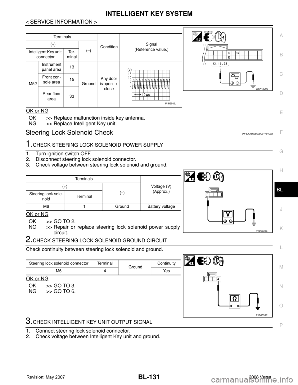
Steering Lock Solenoid CheckINFOID:0000000001704028
1.CHECK STEERING LOCK SOLENOID POWER SUPPLY
1. Turn ignition switch OFF.
2. Disconnect steering lock solenoid connector.
3. Check voltage between steering lock solenoid and ground.
OK or NG
OK >> GO TO 2.
NG >> Repair or replace steering lock solenoid power supply
circuit.
2.CHECK STEERING LOCK SOLENOID GROUND CIRCUIT
Check continuity between steering lock solenoid and ground.
OK or NG
OK >> GO TO 3.
NG >> GO TO 6.
3.CHECK INTELLIGENT KEY UNIT OUTPUT SIGNAL
1. Connect steering lock solenoid connector.
2. Check voltage between Intelligent Key unit and ground.
Te r m i n a l s
ConditionSignal
(Reference value.) (+)
(–)
Intelligent Key unit
connectorTe r -
minal
M52Instrument
panel area13
GroundAny door
is open →
close Front con-
sole area15
Rear floor
area33
WIIA1200E
PIIB5502J
Te r m i n a l s
Voltage (V)
(Approx.) (+)
(–)
Steering lock sole-
noidTe r m i n a l
M6 1 Ground Battery voltage
PIIB6632E
Steering lock solenoid connector Terminal
GroundContinuity
M6 4 Yes
PIIB6633E
Page 583 of 2771
DOOR
BL-149
< SERVICE INFORMATION >
C
D
E
F
G
H
J
K
L
MA
B
BL
N
O
P
3. Remove the check link bolt.
4. Remove the hinge nuts and the door assembly.
Installation
Installation is in the reverse order of removal.
BACK DOOR
Removal
1. Remove the back door glass. Refer toGW-15.
2. Remove the back door lock assembly. Refer to BL-156
.
3. Remove the back door wire harness.
4. Remove the rear washer nozzle and hose from the back door. Refer to WW-31, "
Removal and Installa-
tion".
5. Support the back door.
CAUTION:
Two technicians should be used to avoid damaging the back door during removal.
6. Remove the back door stays.
7. Remove the door side nuts and the back door assembly.
Installation
Installation is in the reverse order of removal.
• Align the back door. Refer to BL-144, "
Fitting Adjustment". 14.7 N·m (1.5 kg-m, 11 ft-lb)
PIIB6543E
24.5 N·m (2.5 kg-m, 18 ft-lb)
PIIB6522E
LIIA2639E
Page 584 of 2771
BL-150
< SERVICE INFORMATION >
FRONT DOOR LOCK
FRONT DOOR LOCK
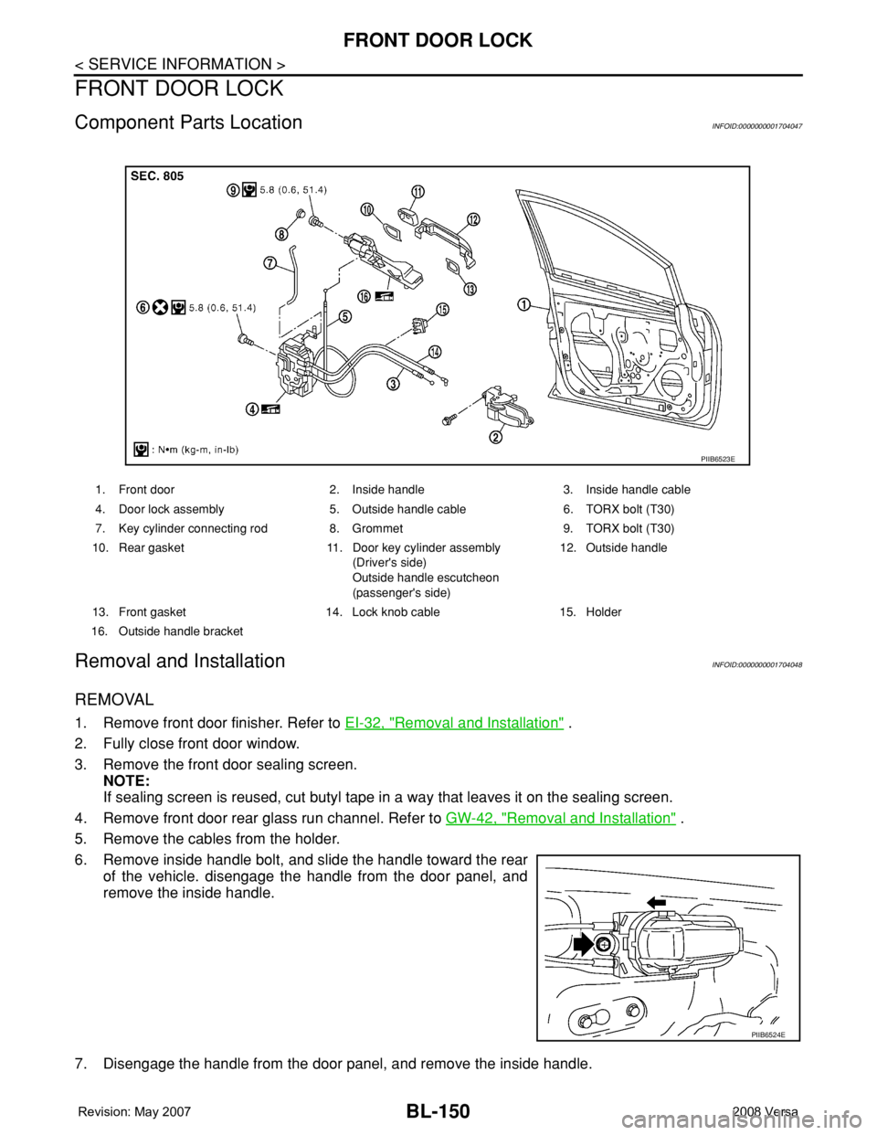
Component Parts LocationINFOID:0000000001704047
Removal and InstallationINFOID:0000000001704048
REMOVAL
1. Remove front door finisher. Refer to EI-32, "Removal and Installation" .
2. Fully close front door window.
3. Remove the front door sealing screen.
NOTE:
If sealing screen is reused, cut butyl tape in a way that leaves it on the sealing screen.
4. Remove front door rear glass run channel. Refer to GW-42, "
Removal and Installation" .
5. Remove the cables from the holder.
6. Remove inside handle bolt, and slide the handle toward the rear
of the vehicle. disengage the handle from the door panel, and
remove the inside handle.
7. Disengage the handle from the door panel, and remove the inside handle.
1. Front door 2. Inside handle 3. Inside handle cable
4. Door lock assembly 5. Outside handle cable 6. TORX bolt (T30)
7. Key cylinder connecting rod 8. Grommet 9. TORX bolt (T30)
10. Rear gasket 11. Door key cylinder assembly
(Driver's side)
Outside handle escutcheon
(passenger's side)12. Outside handle
13. Front gasket 14. Lock knob cable 15. Holder
16. Outside handle bracket
PIIB6523E
PIIB6524E