2008 NISSAN LATIO seat lif
[x] Cancel search: seat lifPage 1654 of 2771
REAR AIR SPOILER
EI-31
< ON-VEHICLE REPAIR >
C
D
E
F
G
H
J
K
L
MA
B
EI
N
O
P
REAR AIR SPOILER
Removal and InstallationINFOID:0000000001704232
Removal
1. Disconnect the negative and positive battery cables.
2. Remove back door finisher upper. Refer to EI-36
.
3. Disconnect high mounted stop lamp connector.
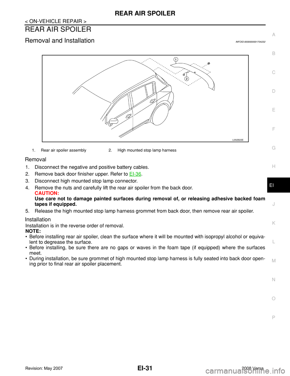
4. Remove the nuts and carefully lift the rear air spoiler from the back door.
CAUTION:
Use care not to damage painted surfaces during removal of, or releasing adhesive backed foam
tapes if equipped.
5. Release the high mounted stop lamp harness grommet from back door, then remove rear air spoiler.
Installation
Installation is in the reverse order of removal.
NOTE:
• Before installing rear air spoiler, clean the surface where it will be mounted with isopropyl alcohol or equiva-
lent to degrease the surface.
• Before installing, be sure there are no gaps or waves in the foam tape (if equipped) where the surfaces
meet.
• During installation, be sure grommet of high mounted stop lamp harness is fully seated into back door open-
ing prior to final rear air spoiler placement.
1. Rear air spoiler assembly 2. High mounted stop lamp harness
LIIA2922E
Page 1675 of 2771
EI-52
< ON-VEHICLE REPAIR >
LUGGAGE FLOOR TRIM
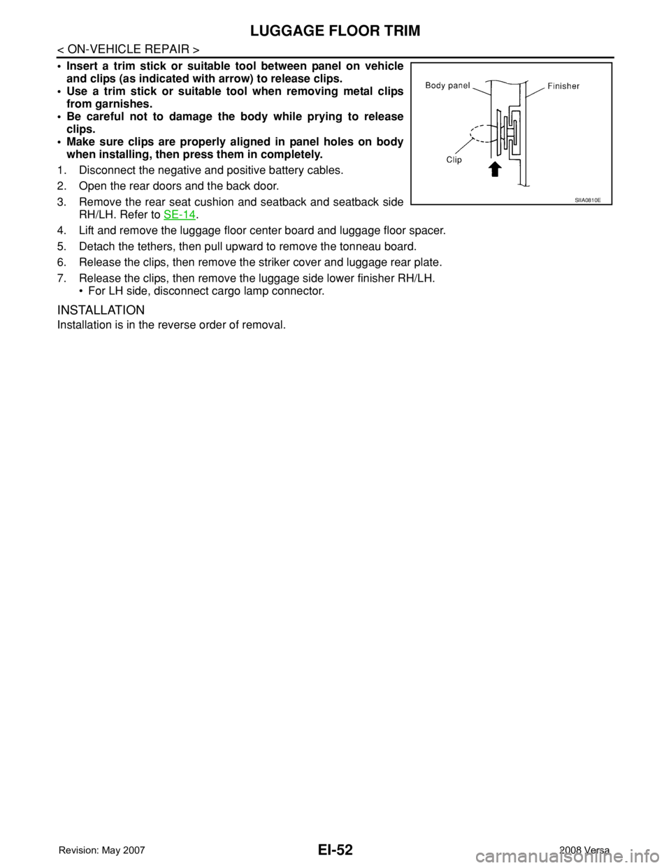
• Insert a trim stick or suitable tool between panel on vehicle
and clips (as indicated with arrow) to release clips.
• Use a trim stick or suitable tool when removing metal clips
from garnishes.
• Be careful not to damage the body while prying to release
clips.
• Make sure clips are properly aligned in panel holes on body
when installing, then press them in completely.
1. Disconnect the negative and positive battery cables.
2. Open the rear doors and the back door.
3. Remove the rear seat cushion and seatback and seatback side
RH/LH. Refer to SE-14
.
4. Lift and remove the luggage floor center board and luggage floor spacer.
5. Detach the tethers, then pull upward to remove the tonneau board.
6. Release the clips, then remove the striker cover and luggage rear plate.
7. Release the clips, then remove the luggage side lower finisher RH/LH.
• For LH side, disconnect cargo lamp connector.
INSTALLATION
Installation is in the reverse order of removal.
SIIA0810E
Page 1676 of 2771
TRUNK ROOM TRIM & TRUNK LID FINISHER
EI-53
< ON-VEHICLE REPAIR >
C
D
E
F
G
H
J
K
L
MA
B
EI
N
O
P
TRUNK ROOM TRIM & TRUNK LID FINISHER
Removal and InstallationINFOID:0000000001704243
REMOVAL
CAUTION:
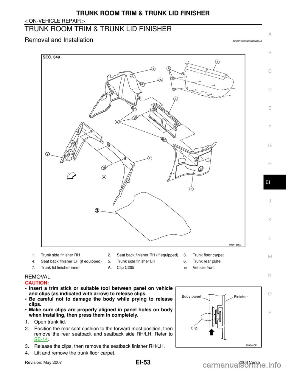
• Insert a trim stick or suitable tool between panel on vehicle
and clips (as indicated with arrow) to release clips.
• Be careful not to damage the body while prying to release
clips.
• Make sure clips are properly aligned in panel holes on body
when installing, then press them in completely.
1. Open trunk lid.
2. Position the rear seat cushion to the forward most position, then
remove the rear seatback and seatback side RH/LH. Refer to
SE-14
.
3. Release the clips, then remove the seatback finisher RH/LH.
4. Lift and remove the trunk floor carpet.
1. Trunk side finisher RH 2. Seat back finisher RH (if equipped) 3. Trunk floor carpet
4. Seat back finisher LH (if equipped) 5. Trunk side finisher LH 6. Trunk rear plate
7. Trunk lid finisher inner A. Clip C205⇐Vehicle front
WIIA1415E
SIIA0810E
Page 1736 of 2771
OIL SEAL
EM-59
< SERVICE INFORMATION >
C
D
E
F
G
H
I
J
K
L
MA
EM
N
P O
OIL SEAL
Removal and Installation of Valve Oil SealINFOID:0000000001702498
REMOVAL
1. Remove camshafts. Refer to EM-47, "Component".
2. Remove valve lifters. Refer to EM-47
.
3. Rotate crankshaft, and set piston whose valve oil seal is to be removed to TDC. This will prevent valve
from dropping into cylinder.
CAUTION:
When rotating crankshaft, be careful to avoid scarring front cover with timing chain.
4. Remove valve collet.
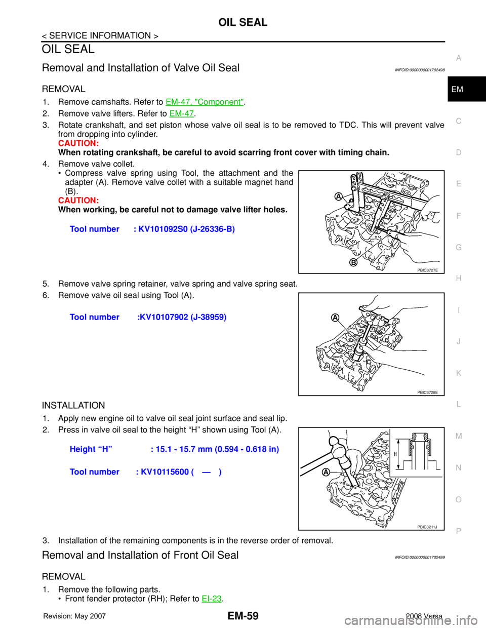
• Compress valve spring using Tool, the attachment and the
adapter (A). Remove valve collet with a suitable magnet hand
(B).
CAUTION:
When working, be careful not to damage valve lifter holes.
5. Remove valve spring retainer, valve spring and valve spring seat.
6. Remove valve oil seal using Tool (A).
INSTALLATION
1. Apply new engine oil to valve oil seal joint surface and seal lip.
2. Press in valve oil seal to the height “H” shown using Tool (A).
3. Installation of the remaining components is in the reverse order of removal.
Removal and Installation of Front Oil SealINFOID:0000000001702499
REMOVAL
1. Remove the following parts.
• Front fender protector (RH); Refer to EI-23
. Tool number : KV101092S0 (J-26336-B)
PBIC3727E
Tool number :KV10107902 (J-38959)
PBIC3728E
Height “H” : 15.1 - 15.7 mm (0.594 - 0.618 in)
Tool number : KV10115600 ( — )
PBIC3211J
Page 1743 of 2771
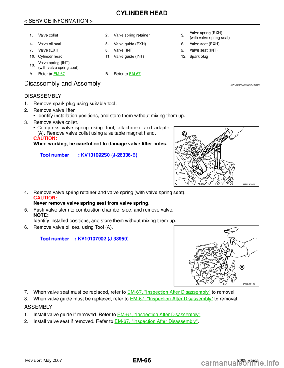
EM-66
< SERVICE INFORMATION >
CYLINDER HEAD
Disassembly and Assembly
INFOID:0000000001702505
DISASSEMBLY
1. Remove spark plug using suitable tool.
2. Remove valve lifter.
• Identify installation positions, and store them without mixing them up.
3. Remove valve collet.
• Compress valve spring using Tool, attachment and adapter
(A). Remove valve collet using a suitable magnet hand.
CAUTION:
When working, be careful not to damage valve lifter holes.
4. Remove valve spring retainer and valve spring (with valve spring seat).
CAUTION:
Never remove valve spring seat from valve spring.
5. Push valve stem to combustion chamber side, and remove valve.
NOTE:
Identify installed positions, and store them without mixing them up.
6. Remove valve oil seal using Tool (A).
7. When valve seat must be replaced, refer to EM-67, "
Inspection After Disassembly" to removal.
8. When valve guide must be replaced, refer to EM-67, "
Inspection After Disassembly" to removal.
ASSEMBLY
1. Install valve guide if removed. Refer to EM-67, "Inspection After Disassembly".
2. Install valve seat if removed. Refer to EM-67, "
Inspection After Disassembly".
1. Valve collet 2. Valve spring retainer 3.Va l v e s p r i n g ( E X H )
(with valve spring seat)
4. Valve oil seal 5. Valve guide (EXH) 6. Valve seat (EXH)
7. Valve (EXH) 8. Valve (INT) 9. Valve seat (INT)
10. Cylinder head 11. Valve guide (INT) 12. Spark plug
13.Valve spring (INT)
(with valve spring seat)
A. Refer to EM-67
B. Refer to EM-67
Tool number : KV101092S0 (J-26336-B)
PBIC3209J
Tool number : KV10107902 (J-38959)
PBIC3210J
Page 1744 of 2771
CYLINDER HEAD
EM-67
< SERVICE INFORMATION >
C
D
E
F
G
H
I
J
K
L
MA
EM
N
P O
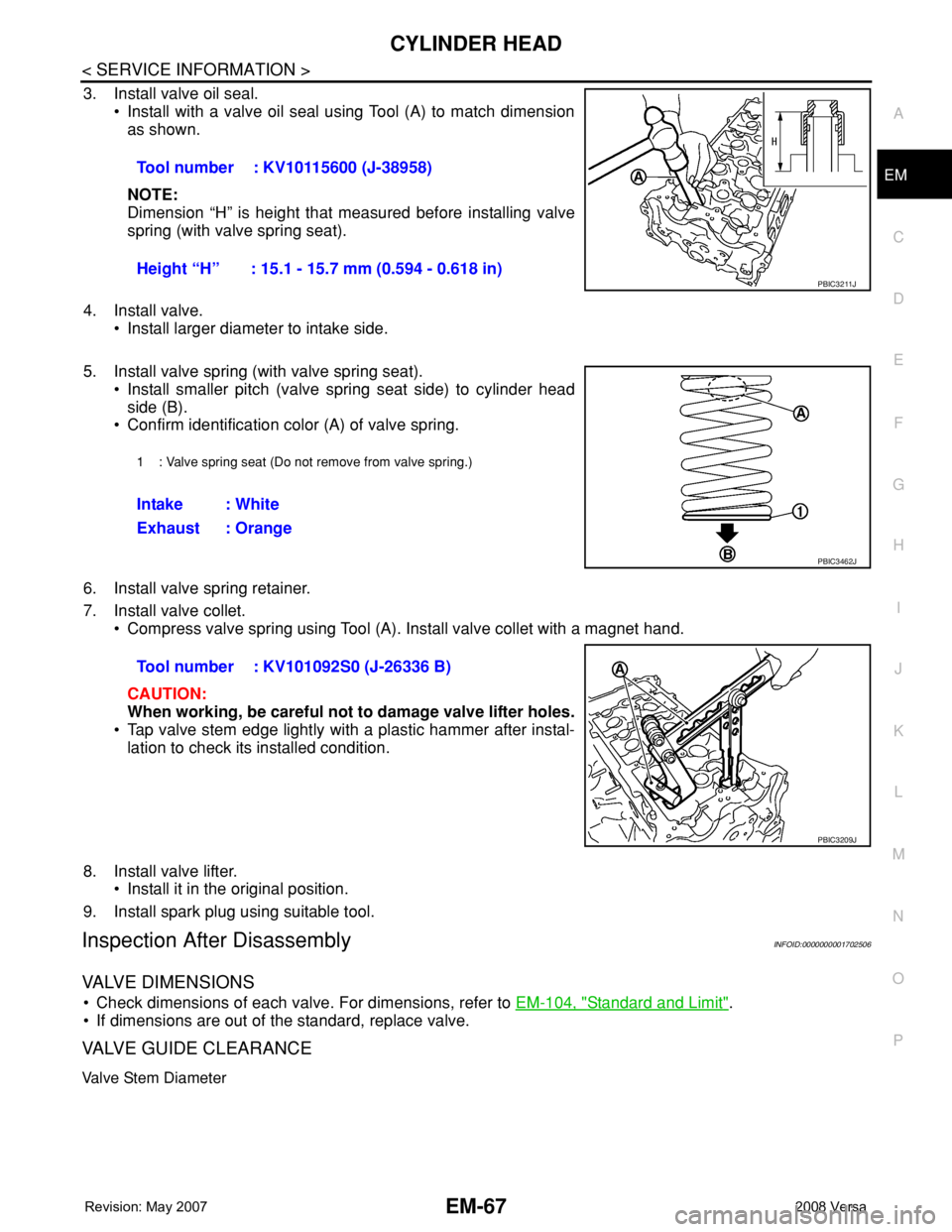
3. Install valve oil seal.
• Install with a valve oil seal using Tool (A) to match dimension
as shown.
NOTE:
Dimension “H” is height that measured before installing valve
spring (with valve spring seat).
4. Install valve.
• Install larger diameter to intake side.
5. Install valve spring (with valve spring seat).
• Install smaller pitch (valve spring seat side) to cylinder head
side (B).
• Confirm identification color (A) of valve spring.
6. Install valve spring retainer.
7. Install valve collet.
• Compress valve spring using Tool (A). Install valve collet with a magnet hand.
CAUTION:
When working, be careful not to damage valve lifter holes.
• Tap valve stem edge lightly with a plastic hammer after instal-
lation to check its installed condition.
8. Install valve lifter.
• Install it in the original position.
9. Install spark plug using suitable tool.
Inspection After DisassemblyINFOID:0000000001702506
VALVE DIMENSIONS
• Check dimensions of each valve. For dimensions, refer to EM-104, "Standard and Limit".
• If dimensions are out of the standard, replace valve.
VALVE GUIDE CLEARANCE
Valve Stem Diameter
Tool number : KV10115600 (J-38958)
Height “H” : 15.1 - 15.7 mm (0.594 - 0.618 in)
PBIC3211J
1 : Valve spring seat (Do not remove from valve spring.)
Intake : White
Exhaust : Orange
PBIC3462J
Tool number : KV101092S0 (J-26336 B)
PBIC3209J
Page 1783 of 2771
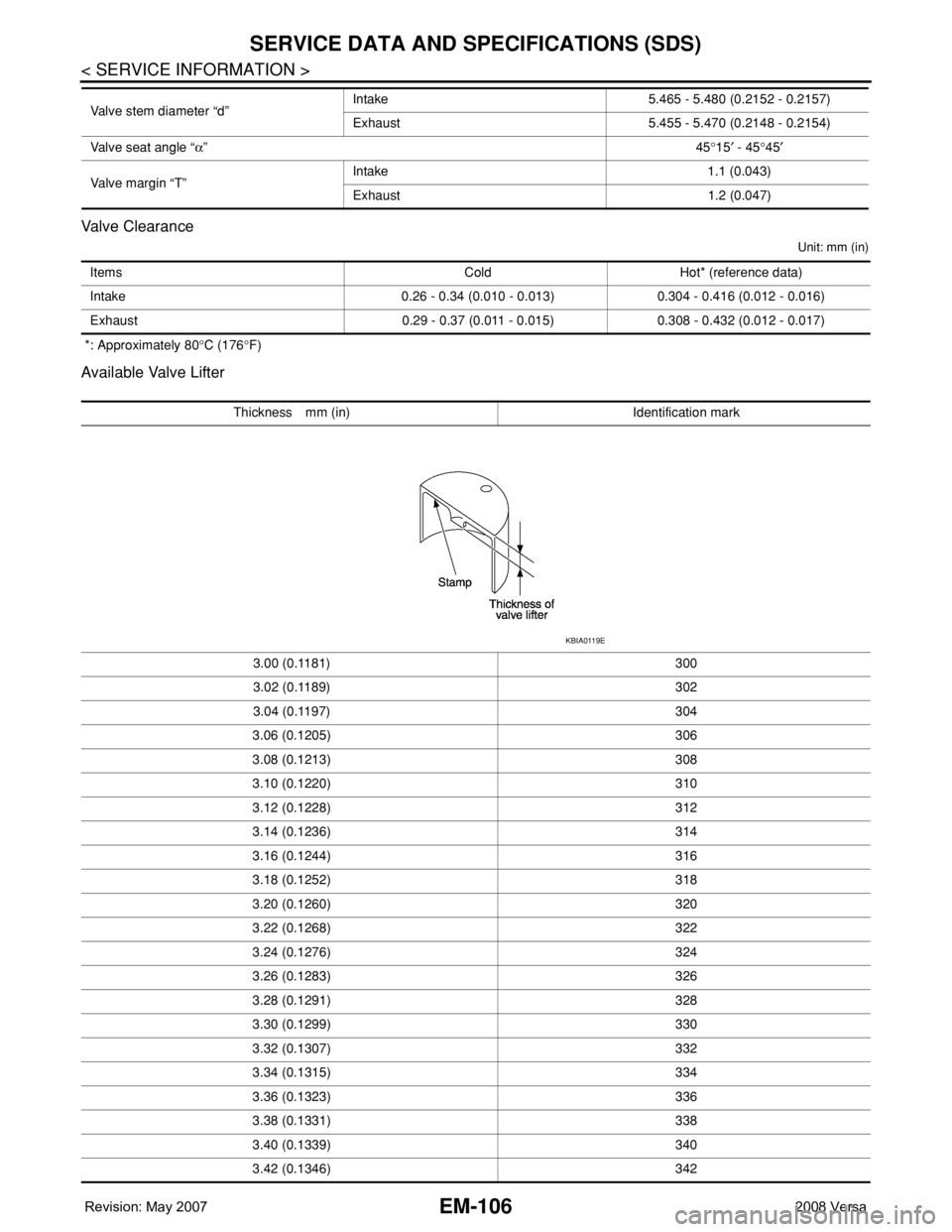
EM-106
< SERVICE INFORMATION >
SERVICE DATA AND SPECIFICATIONS (SDS)
Valve Clearance
Unit: mm (in)
*: Approximately 80°C (176°F)
Available Valve Lifter
Valve stem diameter “d”Intake 5.465 - 5.480 (0.2152 - 0.2157)
Exhaust 5.455 - 5.470 (0.2148 - 0.2154)
Valve seat angle “α”45°15′ - 45°45′
Valve margin “T”Intake 1.1 (0.043)
Exhaust 1.2 (0.047)
Items Cold Hot* (reference data)
Intake 0.26 - 0.34 (0.010 - 0.013) 0.304 - 0.416 (0.012 - 0.016)
Exhaust 0.29 - 0.37 (0.011 - 0.015) 0.308 - 0.432 (0.012 - 0.017)
Thickness mm (in) Identification mark
3.00 (0.1181) 300
3.02 (0.1189) 302
3.04 (0.1197) 304
3.06 (0.1205) 306
3.08 (0.1213) 308
3.10 (0.1220) 310
3.12 (0.1228) 312
3.14 (0.1236) 314
3.16 (0.1244) 316
3.18 (0.1252) 318
3.20 (0.1260) 320
3.22 (0.1268) 322
3.24 (0.1276) 324
3.26 (0.1283) 326
3.28 (0.1291) 328
3.30 (0.1299) 330
3.32 (0.1307) 332
3.34 (0.1315) 334
3.36 (0.1323) 336
3.38 (0.1331) 338
3.40 (0.1339) 340
3.42 (0.1346) 342
KBIA0119E
Page 1784 of 2771
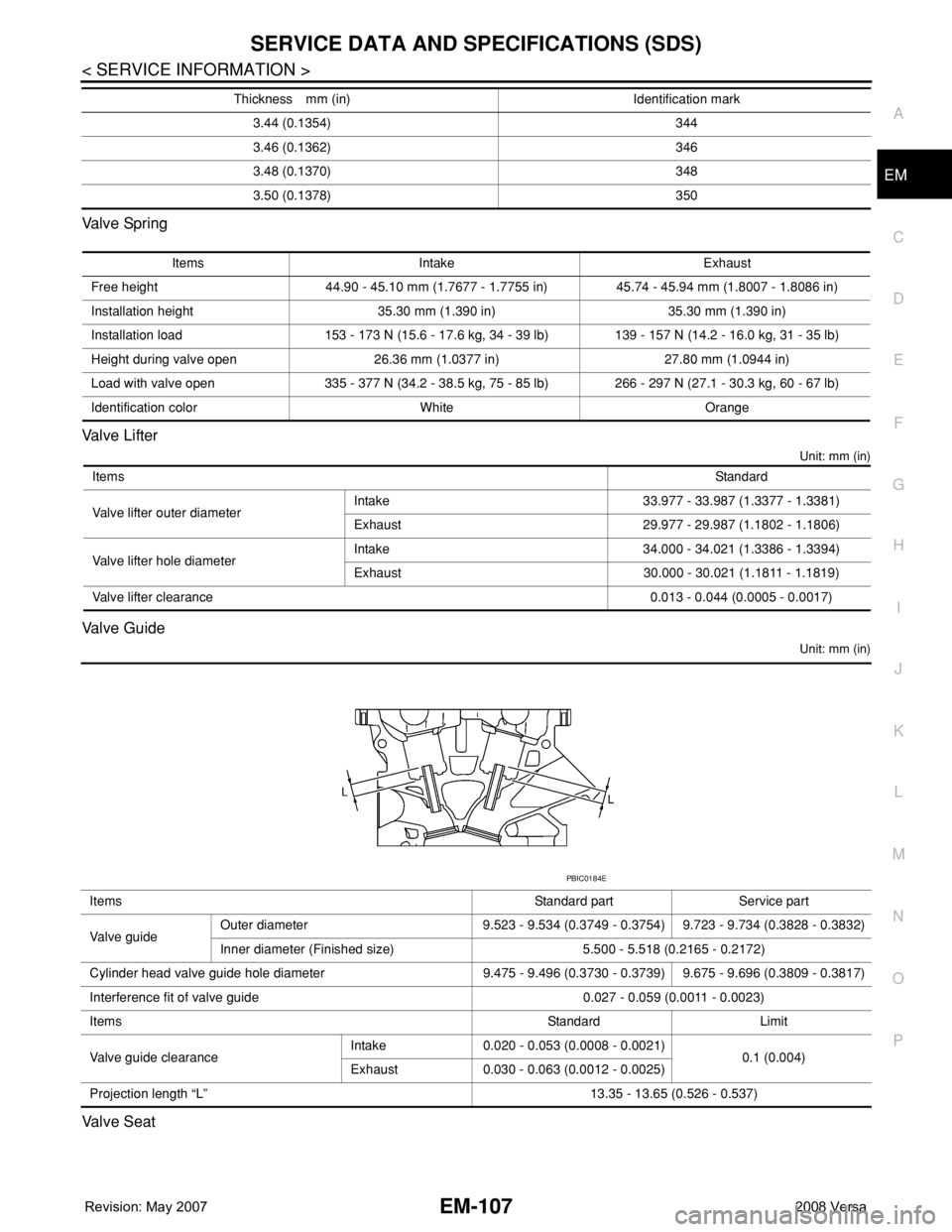
SERVICE DATA AND SPECIFICATIONS (SDS)
EM-107
< SERVICE INFORMATION >
C
D
E
F
G
H
I
J
K
L
MA
EM
N
P O Va l v e Sp r i n g
Valve Lifter
Unit: mm (in)
Valve Guide
Unit: mm (in)
Valve Seat
3.44 (0.1354) 344
3.46 (0.1362) 346
3.48 (0.1370) 348
3.50 (0.1378) 350 Thickness mm (in) Identification mark
Items Intake Exhaust
Free height 44.90 - 45.10 mm (1.7677 - 1.7755 in) 45.74 - 45.94 mm (1.8007 - 1.8086 in)
Installation height 35.30 mm (1.390 in) 35.30 mm (1.390 in)
Installation load 153 - 173 N (15.6 - 17.6 kg, 34 - 39 lb) 139 - 157 N (14.2 - 16.0 kg, 31 - 35 lb)
Height during valve open 26.36 mm (1.0377 in) 27.80 mm (1.0944 in)
Load with valve open 335 - 377 N (34.2 - 38.5 kg, 75 - 85 lb) 266 - 297 N (27.1 - 30.3 kg, 60 - 67 lb)
Identification color White Orange
ItemsStandard
Valve lifter outer diameterIntake 33.977 - 33.987 (1.3377 - 1.3381)
Exhaust 29.977 - 29.987 (1.1802 - 1.1806)
Valve lifter hole diameterIntake 34.000 - 34.021 (1.3386 - 1.3394)
Exhaust 30.000 - 30.021 (1.1811 - 1.1819)
Valve lifter clearance0.013 - 0.044 (0.0005 - 0.0017)
Items Standard part Service part
Va l v e g u i d eOuter diameter 9.523 - 9.534 (0.3749 - 0.3754) 9.723 - 9.734 (0.3828 - 0.3832)
Inner diameter (Finished size) 5.500 - 5.518 (0.2165 - 0.2172)
Cylinder head valve guide hole diameter 9.475 - 9.496 (0.3730 - 0.3739) 9.675 - 9.696 (0.3809 - 0.3817)
Interference fit of valve guide 0.027 - 0.059 (0.0011 - 0.0023)
ItemsStandard Limit
Valve guide clearanceIntake 0.020 - 0.053 (0.0008 - 0.0021)
0.1 (0.004)
Exhaust 0.030 - 0.063 (0.0012 - 0.0025)
Projection length “L” 13.35 - 13.65 (0.526 - 0.537)
PBIC0184E