2008 MERCEDES-BENZ SLK ROADSTER tow bar
[x] Cancel search: tow barPage 119 of 273
Driving sys
tems 11
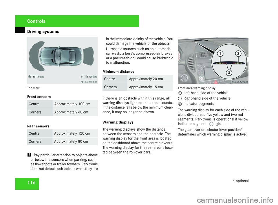
6 Top view
Front sensors
Centre Approximately 100 cm
Corners Approximately 60 cm
Rear sensors
Centre Approximately 120 cm
Corners Approximately 80 cm
!
Pay particular attention to objects above
or below the sensors when parking, such
as flower pots or trailer towbars. Parktronic
does not detect such objects when they are in the immediate vicinity of the vehicle. You
could damage the vehicle or the objects.
Ultrasonic sources such as an automatic
car wash, a lorry's compressed-air brakes
or a pneumatic drill could cause Parktronic
to malfunction.
Minimum distance Centre Approximately 20 cm
Corners Approximately 15 cm
If there is an obstacle within this range, all
warning displays light up and a tone sounds.
If the distance falls below the minimum clear-
ance, it may no longer be shown.
Warning displays
The warning displays show the distance
between the sensors and the obstacle. The
warning display for the front area is located
on the dashboard above the centre air vents.
The warning display for the rear area is loca-
ted between the roll-over bars. Front area warning display
1
Left-hand side of the vehicle
2 Right-hand side of the vehicle
3 Indicator segments
The warning display for each side of the vehi -
cle is divided into five yellow and two red
segments. Parktronic is operational if yellow
indicator segments 3light up.
The gear lever or selector lever position *
determines which warning display is active: Controls
* optional
171_AKB; 3; 4, en-GB
vpfaff7, 2007-11-13T10:50:25+01:00 - Seite 116
Page 138 of 273
Opening/closing the roof
135Closing the boot separator
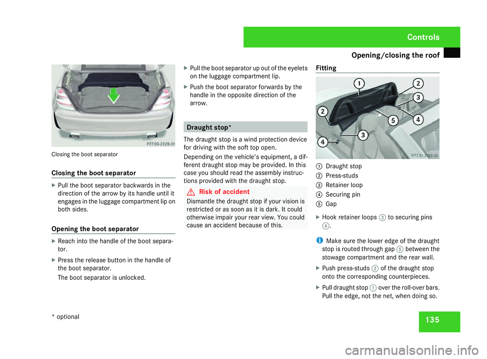
Closing the boot separator
X
Pull the boot separator backwards in the
direction of the arrow by its handle until it
engages in the luggage compartment lip on
both sides.
Opening the boot separator X
Reach into the handle of the boot separa-
tor.
X Press the release button in the handle of
the boot separator.
The boot separator is unlocked. X
Pull the boot separator up out of the eyelets
on the luggage compartment lip.
X Push the boot separator forwards by the
handle in the opposite direction of the
arrow. Draught stop*
The draught stop is a wind protection device
for driving with the soft top open.
Depending on the vehicle's equipment, a dif-
ferent draught stop may be provided. In this
case you should read the assembly instruc-
tions provided with the draught stop. G
Risk of acciden
t
Dismantle the draught stop if your vision is
restricted or as soon as it is dark. It could
otherwise impair your rear view. You could
cause an accident because of this. Fittin
g 1
Draught sto p
2 Press-studs
3 Retainer loop
4 Securing pi n
5 Gap
X Hook retainer loops 3to securing pins
4 .
i Make sure the lower edge of the draught
stop is routed through gap 5between the
stowage compartment and the rear wall.
X Push press-studs 2of the draught stop
onto the corresponding counterpieces.
X Pull draught stop 1over the roll-over bars.
Pull the edge, not the net, when doing so. Controls
* optional
171_AKB; 3; 4, en-GB
vpfaff7,
2007-11-13T10:50:25+01:00 - Seite 135
Page 139 of 273
Loading and stowing
136
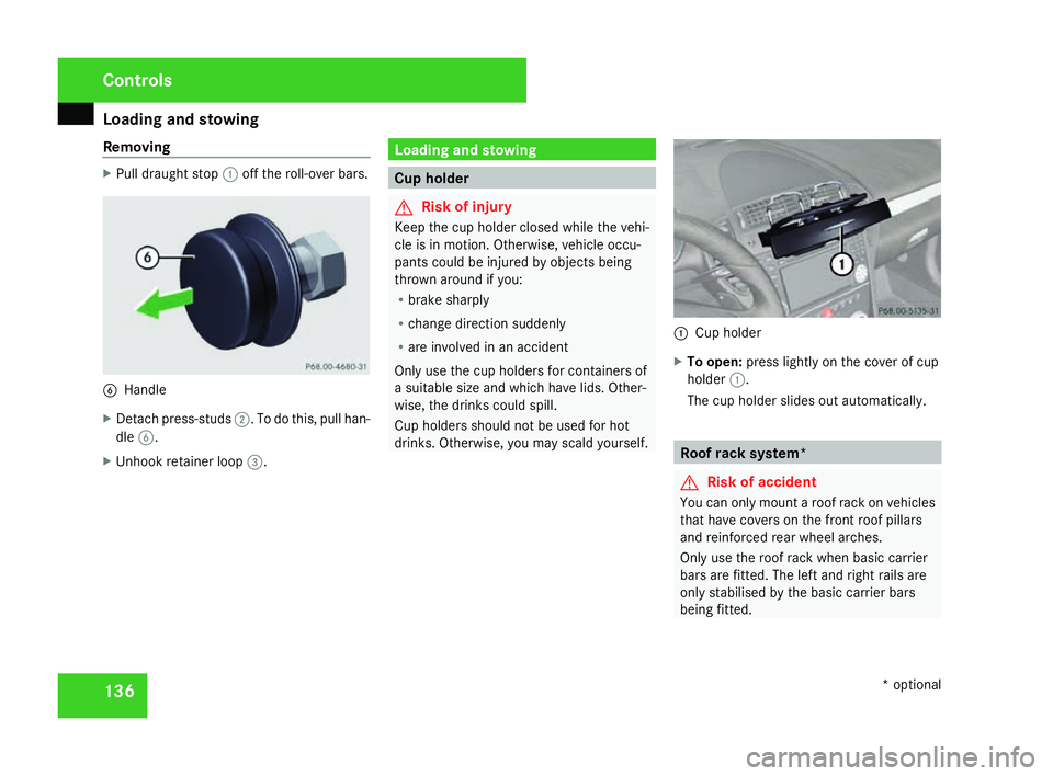
Removing X
Pull draught stop 1off the roll-over bars. 6
Handl e
X Detach press-studs 2. To do this, pull han-
dle 6.
X Unhook retainer loop 3. Loading and stowin
g Cup holder
G
Risk of injury
Keep the cup holder closed while the vehi-
cle is in motion. Otherwise, vehicle occu -
pants could be injured by objects being
thrown around if you:
R brake sharply
R change direction suddenly
R are involved in an acciden t
Only use the cup holders for containers of
a suitable size and which have lids. Other-
wise, the drinks could spill.
Cup holders should not be used for hot
drinks. Otherwise, you may scald yourself. 1
Cup holder
X To open: press lightly on the cover of cup
holder 1.
The cup holder slides out automatically. Roof rack system*
G
Risk of accident
You can only mount a roof rack on vehicles
that have covers on the front roof pillars
and reinforced rear wheel arches.
Only use the roof rack when basic carrie r
bars are fitted. The left and right rails are
only stabilised by the basic carrier bars
being fitted. Controls
* optional
171_AKB; 3; 4, en-GB
vpfaff7,
2007-11-13T10:50:25+01:00 - Seite 136
Page 140 of 273
Loading and stowing
137An incorrectly secured roof rack or load
could work loose from the vehicle and
thereby cause an accident. Follow the roo
f
rack manufacturer's installation instruc-
tions and special instructions for use.
The roof load raises the vehicle's centre of
gravity, thereby affecting vehicle handling.
You must observe the maximum roof load
of 50 kg. Always adapt your driving style to
the prevailing road, traffic and weather con-
ditions and drive with particular care if the
roof is laden.
! Mercedes-Benz recommends that you
only use roof rack systems which have
been tested and approved for Mercedes-
Benz vehicles. This helps to prevent dam-
age to the vehicle.
Position the load on the roof rack in such a
way that the vehicle will not sustain dam-
age even when it is in motion .
Do not open the roof if a roof rack is fitted.
You will otherwise damage the roof.
Leave the boot separator in the boot open
for protection.
Make sure that you can open the boot li d
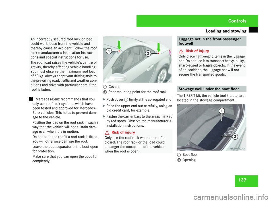
completely . 1
Cover s
2 Rear mounting point for the roof rac k
X Push cover 1firmly at the corrugated end.
X Prise the upper end out carefully, using an
old credit card, for example.
X Fasten the carrier bars to the areas marked
by red spots. Observe the manufacturer's
installation instructions. G
Risk of injury
Only use the roof rack when the roof is
closed. The roof rack or the load could
endanger the occupants of the vehicl e
when the roof is open. Luggage net in the front-passenger
footwell
G
Risk of injury
Only place lightweight items in the luggag e
net. Do not use it to transport heavy, bulky ,
sharp-edged or fragile objects. In the event
of an accident, the luggage net will not
secure the transported goods . Stowage well under the boot floor
The TIREFIT kit, the vehicle tool kit, etc. are
located in the stowage compartment. 1
Boot floor
2 Opening Controls
171_AKB; 3; 4, en-GB
vpfaff7,
2007-11-13T10:50:25+01:00 - Seite 137
Page 222 of 273
Flat tyre
219
For all vehicles X
All occupants must get out of the vehicle.
Make sure that they are not endangered as
they do so.
X Make sure that no one is near the danger
area whilst a wheel is being changed. Any-
one who is not directly assisting in the
wheel change should, for example, stand
behind the barrier.
X Switch off the engine.
X Remove the key from the ignition lock.
X Place the warning triangle (Y page 172) or
warning lamps at a suitable distance.
Observe legal requirements. G
Risk of injury
The jack is designed only to raise the vehi-
cle for a short time while a wheel is being
changed .
If you intend to work under the vehicle, it
must be placed on stands.
Make sure that the jack is placed on a firm,
non-slip, level surface. Do not use wooden
blocks or similar as jacking supports. Oth-
erwise, the jack will not be able to achieve
its load-bearing capacity due to the restric-
ted height. Do not start the engine at any time while
the wheel is being changed.
Do not lie under the vehicle when it is being
supported by the jack. If you do not rais
e
the vehicle as described, it could slip off the
jack (e.g. if the engine is started or a door
or the boot lid are opened or closed) and
you could be seriously injured . Using the TIREFIT kit
You can use the TIREFIT kit to seal small
punctures, particularly those in the tyre tread.
You can use TIREFIT in outdoor temperature s
down to -20 °C. G
Risk of accident
In the following situations, your safety is at
particular risk and TIREFIT is unable to pro -
vide breakdown assistance:
R if there are cuts or punctures in the tyre
greater than 4 mm
R if the wheel rim is damaged
R if you have driven at very low tyre pres-
sures or on a flat tyre
Do not drive any further. Consult a qualified
specialist workshop which has the neces- sary specialist knowledge and tools to carr
y
out the work required.
Mercedes-Benz recommends that you use
a Mercedes-Benz Service Centre for this
purpose. In particular, work relevant to
safety or on safety-related systems must be
carried out at a qualified specialist work-
shop.
X Do not remove any foreign objects which
have penetrated the tyre, e.g. screws or
nails .
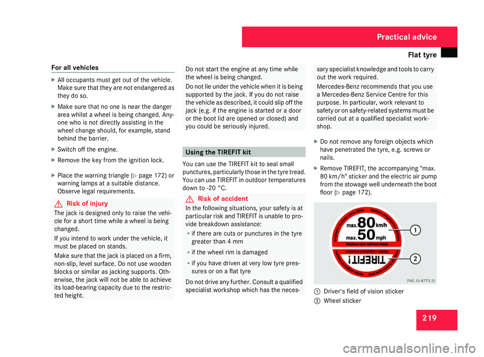
X Remove TIREFIT, the accompanying "max .
80 km/h" sticker and the electric air pum p
from the stowage well underneath the boot
floor (Y page 172). 1
Driver's field of vision sticker
2 Wheel sticker Practical advice
171_AKB; 3; 4, en-GB
vpfaff7
, 2007-11-13T10:50:25+01:00 - Seite 219
Page 225 of 273
Flat tyre
222 G
Risk of accident
If a pressure of 1.8 bar is not achieved afte r
five minutes, the tyre is too badly damaged.
Do not drive any further. Consult a qualified
specialist workshop which has the neces-
sary specialist knowledge and tools to carry
out the work required. Mercedes-Benz rec-
ommends that you use a Mercedes-Benz
Service Centre for this purpose. In particu-
lar, work relevant to safety or on safety-
related systems must be carried out at a
qualified specialist workshop.
If a tyre pressure of 1.8 bar is reached:
X Press on/off switch 4on the electric air
pump to 0.
The electric air pump is switched off.
X Disconnect the electric air pump and stow
it away .
X Fold up the warning triangle and stow it
away .
X Pull away immediately.
This distributes the TIREFIT more evenly
around the tyre.
X Stop after driving for approximately ten
minutes and check the tyre pressure with
the electric air pump. G
Risk of accident
If the tyre pressure is now lower than
1.3 bar, the tyre is too badly damaged. Do
not drive any further. Consult a qualified
specialist workshop which has the neces -
sary specialist knowledge and tools to carry
out the work required. Mercedes-Benz rec-
ommends that you use a Mercedes-Benz
Service Centre for this purpose. In particu-
lar, work relevant to safety or on safety-
related systems must be carried out at a
qualified specialist workshop.
X If the tyre pressure is still at least 1.3 bar,
correct it (see fuel filler flap for values).
To increase the tyre pressure: switch on
the electric air pump.
To reduce the tyre pressure: open pres-
sure release screw aon pressure
gauge b.
X Drive to the nearest workshop and have the
tyre changed there.
X Have the TIREFIT kit replaced as soon as
possible at a qualified specialist workshop ,
e.g. at a Mercedes-Benz Service Centre. G
Risk of accident
Do not exceed the maximum speed of 80
km/h.
The “max. 80 km/h” sticker must be affixe d
within the driver's field of vision.
The vehicle's handling characteristics may
be affected. H
Environmental not
e
Have the used TIREFIT kit disposed of pro-
fessionally, e.g. at a Mercedes-Benz
Service Centre.
X Have the TIREFIT kit replaced every fou r
years at a qualified specialist workshop ,
e.g. a Mercedes-Benz Service Centre. Practical advice
171_AKB; 3; 4, en-GB
vpfaff7
, 2007-11-13T10:50:25+01:00 - Seite 222
Page 227 of 273
Flat tyre
224 G
Risk of accident
If a pressure of 1.8 bar is not achieved afte r
five minutes, the tyre is too badly damaged.
Do not drive any further. Consult a qualified
specialist workshop which has the neces-
sary specialist knowledge and tools to carry
out the work required. Mercedes-Benz rec-
ommends that you use a Mercedes-Benz
Service Centre for this purpose. In particu-
lar, work relevant to safety or on safety-
related systems must be carried out at a
qualified specialist workshop.
If a tyre pressure of 1.8 bar is reached:
X Press on/off switch 3on the electric air
pump to 0.
The electric air pump is switched off.
X Disconnect the electric air pump and stow
it away .
X Fold up the warning triangle and stow it
away .
X Pull away immediately.
This distributes the TIREFIT more evenly
around the tyre.
X Stop after driving for approximately ten
minutes and check the tyre pressure with
the electric air pump. G
Risk of accident
If the tyre pressure is now lower than
1.3 bar, the tyre is too badly damaged. Do
not drive any further. Consult a qualified
specialist workshop which has the neces -
sary specialist knowledge and tools to carry
out the work required. Mercedes-Benz rec-
ommends that you use a Mercedes-Benz
Service Centre for this purpose. In particu-
lar, work relevant to safety or on safety-
related systems must be carried out at a
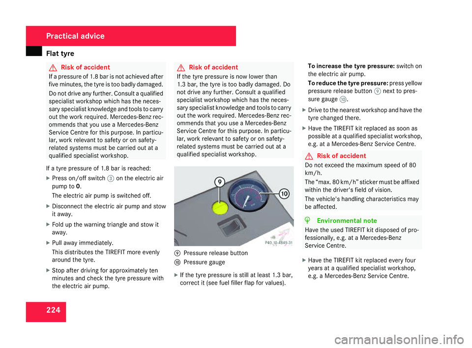
qualified specialist workshop. 9
Pressure release button
a Pressure gauge
X If the tyre pressure is still at least 1.3 bar,
correct it (see fuel filler flap for values). To increase the tyre pressure
:switch on
the electric air pump .
To reduce the tyre pressure :press yellow
pressure release button 9next to pres -
sure gauge a.
X Drive to the nearest workshop and have the
tyre changed there .
X Have the TIREFIT kit replaced as soon as
possible at a qualified specialist workshop ,
e.g. at a Mercedes-Benz Service Centre. G
Risk of acciden
t
Do not exceed the maximum speed of 80
km/h .
The “max. 80 km/h” sticker must be affixed
within the driver's field of vision.
The vehicle's handling characteristics may
be affected. H
Environmental note
Have the used TIREFIT kit disposed of pro-
fessionally, e.g. at a Mercedes-Ben z
Service Centre.
X Have the TIREFIT kit replaced every fou r
years at a qualified specialist workshop ,
e.g. a Mercedes-Benz Service Centre. Practical advice
171_AKB; 3; 4, en-GB
vpfaff7,
2007-11-13T10:50:25+01:00 - Seite 224
Page 231 of 273
Flat tyre
228
X
Unscrew the centring pin.
X Tighten the last wheel bolt until it is finger-
tight .
Inflating the collapsible emergency
spare wheel* with the electric air pump G
Risk of accident
Pump up the collapsible emergency spare
wheel before lowering the vehicle, as yo u
could otherwise damage the wheel rim.
The electric air pump is located in the stow -
age well under the boot floor.
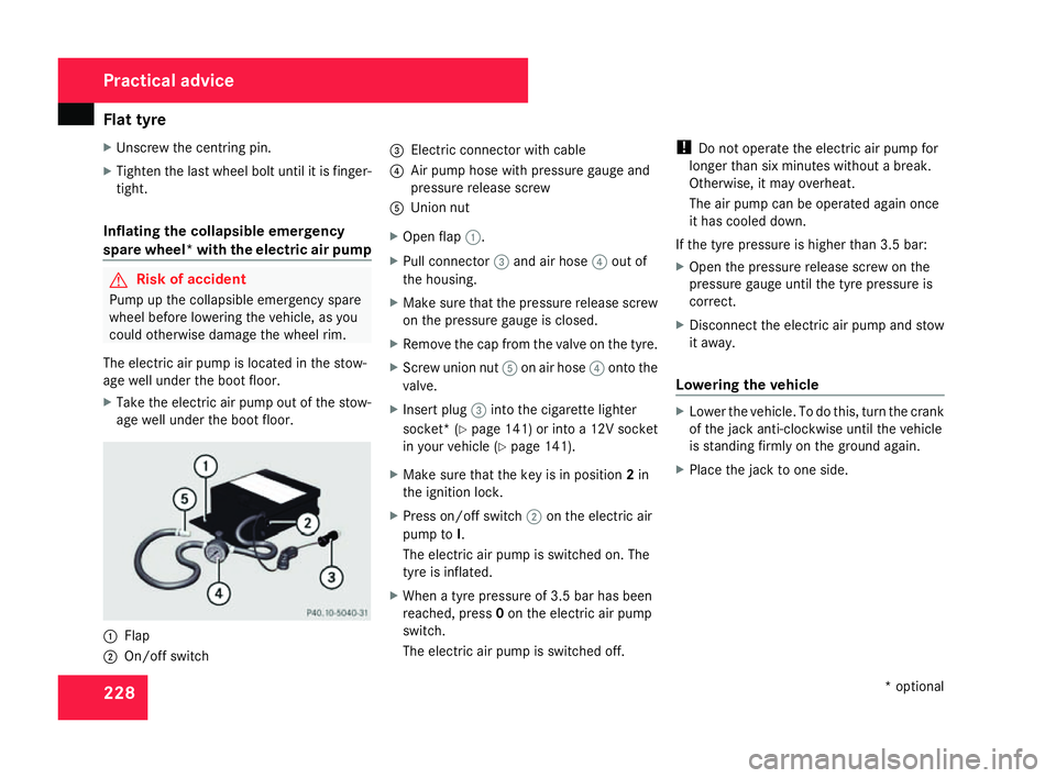
X Take the electric air pump out of the stow-
age well under the boot floor. 1
Flap
2 On/off switch 3
Electric connector with cable
4 Air pump hose with pressure gauge and
pressure release scre w
5 Union nut
X Open flap 1.
X Pull connector 3and air hose 4out of
the housing.
X Make sure that the pressure release screw
on the pressure gauge is closed.
X Remove the cap from the valve on the tyre.
X Screw union nut 5on air hose 4onto the
valve.
X Insert plug 3into the cigarette lighter
socket* (Y page 141 )or into a 12V socket
in your vehicle (Y page 141).
X Make sure that the key is in position 2in
the ignition lock .
X Press on/off switch 2on the electric air
pump to I.
The electric air pump is switched on. The
tyre is inflated.
X When a tyre pressure of 3.5 bar has been
reached, press 0on the electric air pump
switch.
The electric air pump is switched off. !
Do not operate the electric air pump for
longer than six minutes without a break.
Otherwise, it may overheat.
The air pump can be operated again once
it has cooled down.
If the tyre pressure is higher than 3.5 bar:
X Open the pressure release screw on the
pressure gauge until the tyre pressure is
correct.
X Disconnect the electric air pump and stow
it away .
Lowering the vehicle X
Lower the vehicle. To do this, turn the crank
of the jack anti-clockwise until the vehicle
is standing firmly on the ground again.
X Place the jack to one side. Practical advice
* optional
171_AKB; 3; 4, en-GB
vpfaff7
, 2007-11-13T10:50:25+01:00 - Seite 228