2008 MERCEDES-BENZ SLK ROADSTER flat tire
[x] Cancel search: flat tirePage 9 of 273
6
Emergency running mod
e
Automatic transmission . . . . . . . . .203
Emergency unlocking
Boot . . . . . . . . . . . . . . . . . . . . . . . .211
Vehicle . . . . . . . . . . . . . . . . . . . . . .210
Engine
Display message . . . . . . . . . . . . . .187
Running irregularl y.. . . . . . . . . . . .201
Starting problems . . . . . . . . . . . . .201
Starting with the key . . . . . . . . . . . .81
Technical data . . . . . . . . . . . . . . . .244
Engine diagnostic warning lamp . ..1 95
Engine electronics . . . . . . . . . . . . . ..241
Malfunction . . . . . . . . . . . . . . . . . .201
Engine number . . . . . . . . . . . . . . . . . .243
Engine oil . . . . . . . . . . . . . . . . . . . . . .258
Checking the oil level (dipstick) . . .153
Checking the oil level (on-board
computer) . . . . . . . . . . . . . . . . . . .152
Consumption . . . . . . . . . . . . . . . . .151
Display message . . . . . . . . . . . . . . . . . . .152, 186, 187
Filler neck . . . . . . . . . . . . . . . . . . .153
Temperature display (on-board
computer) . . . . . . . . . . . . . . . . . . . .96
Topping up . . . . . . . . . . . . . . . . . . .153
ESP ®
(Electronic Stability Program) .51
Activating/deactivating . . . . . . . . . .51
Display message . . . . . . . . . .176, 177
Warning lamp . . . . . . . . . . . . . .51, 194 Exterior lighting
Delayed switch-off (on-board
computer) . . . . . . . . . . . . . . . . . . .105
Exterior mirror parking position
Storing . . . . . . . . . . . . . . . . . . . .67, 69
Exterior mirrors
Adjusting . . . . . . . . . . . . . . . . . . . . .66
Anti-dazzle mode (automatic) . . . . .67
Folding in/out (automatically ).. . . .66
Folding in/out (electrically) . . . . . . .66
Folding in when locking (on-board
computer) . . . . . . . . . . . . . . . . . . .106
Malfunction . . . . . . . . . . . . . . . . . .206
Parking position . . . . . . . . . . . . .67, 69
Resetting . . . . . . . . . . . . . . . . . . . . .66
Storing settings . . . . . . . . . . . . . . . .68
Exterior view
Overview . . . . . . . . . . . . . . . . . . . . .18 F
Fire extinguishe r. . . . . . . . . . . . . . . .174
First-aid kit . . . . . . . . . . . . . . . . . . . . .174
Flat tyre Preparing the vehicle . . . . . . . . . . .218
TIREFIT kit . . . . . . . . . . . . . . . . . . .219
Floormat . . . . . . . . . . . . . . . . . . . . . . .146
Foglamps Display message . . . . . . . . . . . . . .185
Fording . . . . . . . . . . . . . . . . . . . . . . . .164 Frequencies
Garage door opene r.. . . . . . . . . . .262
Telephone . . . . . . . . . . . . . . . . . . .242
Front airbag . . . . . . . . . . . . . . . . . . . . .42
Front-passenger airbag . . . . . . . . . . ..42
Fuel . . . . . . . . . . . . . . . . . . . . . . . . . . .255
Loss . . . . . . . . . . . . . . . . . . . . . . . .200
Petrol . . . . . . . . . . . . . . . . . . . . . . .149
Fuel consumptio n. . . . . . . . . . .256, 257
Fuel filler flap Opening/closing . . . . . . . . . . . . . .148
Fuel lin e
Malfunction . . . . . . . . . . . . . . . . . .200
Fuel tank
Malfunction . . . . . . . . . . . . . . . . . .200
Fuse allocation chart . . . . . . . . . . ..237
Fuse box Boot . . . . . . . . . . . . . . . . . . . . . . . .238
Dashboard . . . . . . . . . . . . . . . . . . .238
Engine compartment . . . . . . . . . . .238
Fuse s. . . . . . . . . . . . . . . . . . . . . . . . . .237 G
Garage door Opening/closing (with the remote
control) . . . . . . . . . . . . . . . . . . . . .145
Garage door opener . . . . . . . . . . . . ..144
Clearing the memory . . . . . . . . . . .146 Index
171_AKB; 3; 4, en-GB
vpfaff7,
2007-11-13T10:50:25+01:00 - Seite
6
Page 175 of 273
Where will I find...?
172 Where will I find...?
Warning triangle
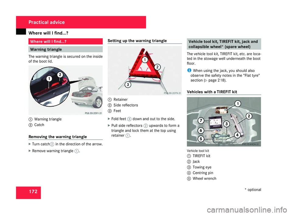
The warning triangle is secured on the insid e
of the boot lid. 1
Warning triangle
2 Catc h
Removing the warning triangl eX
Turn catch 2in the direction of the arrow.
X Remove warning triangle 1. Setting up the warning triangle 1
Retainer
2 Side reflectors
3 Fee t
X Fold feet 3down and out to the side.
X Pull side reflectors 2upwards to form a
triangle and lock them at the top using
retainer 1. Vehicle tool kit, TIREFIT kit, jack and
collapsible wheel *(spare wheel)
The vehicle tool kit, TIREFIT kit, etc. are loca-
ted in the stowage well underneath the boot
floor .
i When using the jack, you should also
observe the safety notes in the "Flat tyre"
section (Y page 218).
Vehicles with a TIREFIT kit Vehicle tool kit
1
TIREFIT kit
2 Jack
3 Towing eye
4 Centring pin
5 Wheel wrench Practical advice
* optional
171_AKB; 3; 4, en-GB
vpfaff7,
2007-11-13T10:50:25+01:00 - Seite 172
Page 221 of 273
Flat tyre
218 Removin
g
X Make sure that the key is in position 1or
2 in the ignition lock .
X Set the windscreen wipers to position II
( Y page 78) on the combination switch.
X When the wiper arms have reached a ver-
tical position, turn the key to position 0and
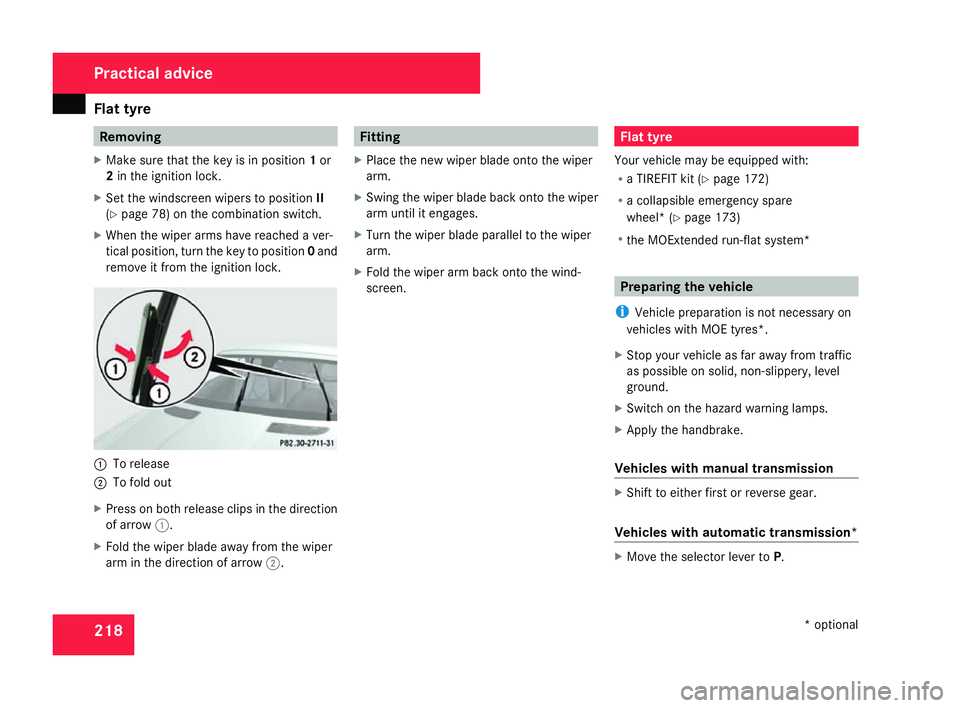
remove it from the ignition lock. 1
To release
2 To fold out
X Press on both release clips in the direction
of arrow 1.
X Fold the wiper blade away from the wipe r
arm in the direction of arrow 2. Fitting
X Place the new wiper blade onto the wiper
arm.
X Swing the wiper blade back onto the wipe r
arm until it engages.
X Turn the wiper blade parallel to the wiper
arm.
X Fold the wiper arm back onto the wind-
screen. Flat tyre
Your vehicle may be equipped with:
R a TIREFIT kit (Y page 172)
R a collapsible emergency spare
wheel* (Y page 173)
R the MOExtended run-flat system* Preparing the vehicle
i Vehicle preparation is not necessary on
vehicles with MOE tyres*.
X Stop your vehicle as far away from traffi c
as possible on solid, non-slippery, level
ground.
X Switch on the hazard warning lamps.
X Apply the handbrake.
Vehicles with manual transmissio n X
Shift to either first or reverse gear .
Vehicles with automatic transmission* X
Move the selector lever to P. Practical advice
* optional
171_AKB; 3; 4, en-GB
vpfaff7,
2007-11-13T10:50:25+01:00 - Seite 218
Page 222 of 273
Flat tyre
219
For all vehicles X
All occupants must get out of the vehicle.
Make sure that they are not endangered as
they do so.
X Make sure that no one is near the danger
area whilst a wheel is being changed. Any-
one who is not directly assisting in the
wheel change should, for example, stand
behind the barrier.
X Switch off the engine.
X Remove the key from the ignition lock.
X Place the warning triangle (Y page 172) or
warning lamps at a suitable distance.
Observe legal requirements. G
Risk of injury
The jack is designed only to raise the vehi-
cle for a short time while a wheel is being
changed .
If you intend to work under the vehicle, it
must be placed on stands.
Make sure that the jack is placed on a firm,
non-slip, level surface. Do not use wooden
blocks or similar as jacking supports. Oth-
erwise, the jack will not be able to achieve
its load-bearing capacity due to the restric-
ted height. Do not start the engine at any time while
the wheel is being changed.
Do not lie under the vehicle when it is being
supported by the jack. If you do not rais
e
the vehicle as described, it could slip off the
jack (e.g. if the engine is started or a door
or the boot lid are opened or closed) and
you could be seriously injured . Using the TIREFIT kit
You can use the TIREFIT kit to seal small
punctures, particularly those in the tyre tread.
You can use TIREFIT in outdoor temperature s
down to -20 °C. G
Risk of accident
In the following situations, your safety is at
particular risk and TIREFIT is unable to pro -
vide breakdown assistance:
R if there are cuts or punctures in the tyre
greater than 4 mm
R if the wheel rim is damaged
R if you have driven at very low tyre pres-
sures or on a flat tyre
Do not drive any further. Consult a qualified
specialist workshop which has the neces- sary specialist knowledge and tools to carr
y
out the work required.
Mercedes-Benz recommends that you use
a Mercedes-Benz Service Centre for this
purpose. In particular, work relevant to
safety or on safety-related systems must be
carried out at a qualified specialist work-
shop.
X Do not remove any foreign objects which
have penetrated the tyre, e.g. screws or
nails .
X Remove TIREFIT, the accompanying "max .
80 km/h" sticker and the electric air pum p
from the stowage well underneath the boot
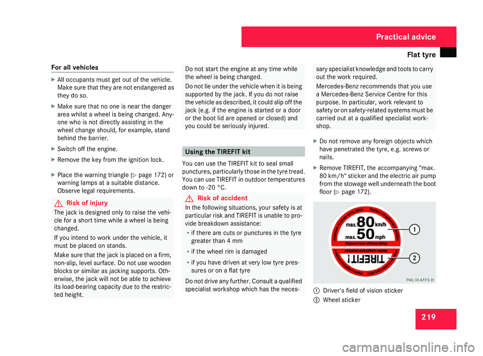
floor (Y page 172). 1
Driver's field of vision sticker
2 Wheel sticker Practical advice
171_AKB; 3; 4, en-GB
vpfaff7
, 2007-11-13T10:50:25+01:00 - Seite 219
Page 223 of 273
Flat tyre
220
X
Affix part 1of the sticker within the driv-
er's field of vision.
X Affix part 2of the sticker near the valve
on the wheel with the defective tyre. G
Risk of injury
TIREFIT must not come into contact with
your skin, eyes or clothing .
R If TIREFIT comes into contact with your
eyes or skin, immediately rinse thor -
oughly with clean water.
R Change out of clothing which has come
into contact with TIREFIT immediately.
R If an allergic reaction occurs, consult a
doctor immediately.
Keep TIREFIT away from children .
R If TIREFIT is swallowed, immediately
rinse your mouth out thoroughly with
water and drink plenty of water.
R Do not induce vomiting. Consult a doctor
immediately.
R Do not inhale TIREFIT fumes .
i If TIREFIT leaks out, allow it to dry. It can
then be removed like a layer of film. If you get TIREFIT on your clothing, have it
cleaned as soon as possible with perchloro
-
ethylene. G
Risk of injury
Comply with the manufacturer's safety
instructions shown on the sticker on the
electric air pump.
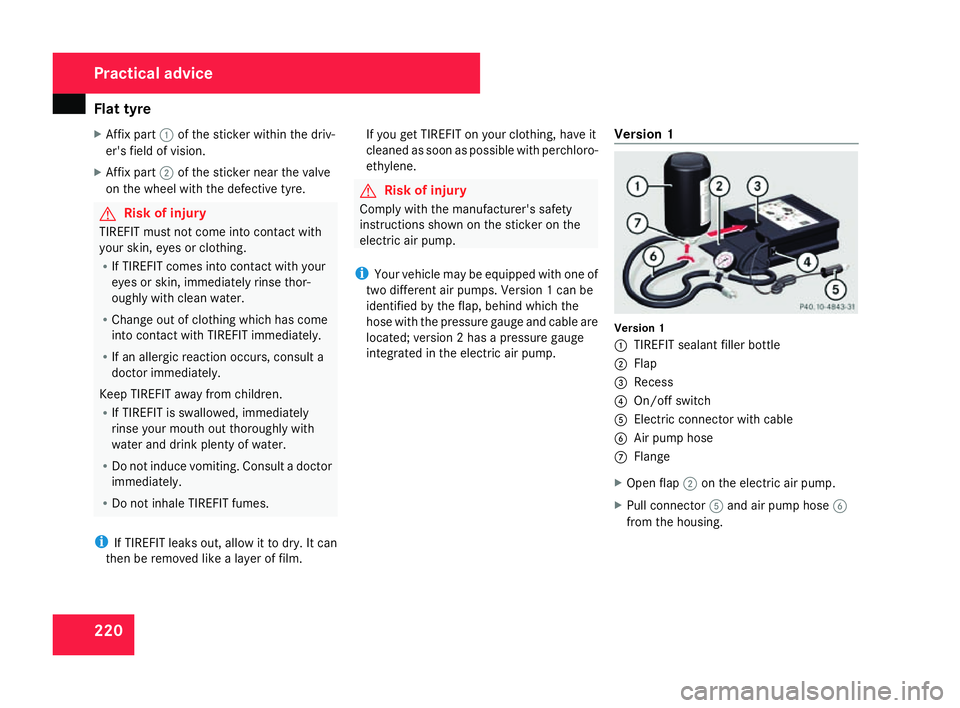
i Your vehicle may be equipped with one of
two different air pumps. Version 1 can be
identified by the flap, behind which the
hose with the pressure gauge and cable are
located; version 2 has a pressure gauge
integrated in the electric air pump. Version
1 Version
1
1 TIREFIT sealant filler bottle
2 Flap
3 Recess
4 On/off switch
5 Electric connector with cable
6 Air pump hos e
7 Flange
X Open flap 2on the electric air pump.
X Pull connector 5and air pump hose 6
from the housing. Practical advic
e
171_AKB; 3; 4, en-GB
vpfaff7,
2007-11-13T10:50:25+01:00 - Seite 220
Page 224 of 273
Flat tyre
221
X
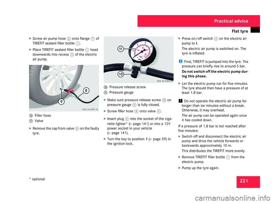
Screw air pump hose 6onto flange 7of
TIREFIT sealant filler bottle 1.
X Place TIREFIT sealant filler bottle 1head
downwards into recess 3of the electric
air pump. 8
Filler hos e
9 Valve
X Remove the cap from valve 9on the faulty
tyre. a
Pressure release screw
b Pressure gauge
X Make sure pressure release screw aon
pressure gauge bis fully closed.
X Screw filler hose 8onto valve 9.
X Insert plug 5into the socket of the ciga-
rette lighter* (Y page 141) or into a 12V
power socket in your vehicle
( Y page 141).
X Turn the key to position 1(Y page 59) in
the ignition lock. X
Press on/off switch 4on the electric air
pump to I.
The electric air pump is switched on. The
tyre is inflated.
i First, TIREFIT is pumped into the tyre. The
pressure can briefly rise to around 5 bar.
Do not switch off the electric pump dur-
ing this phase.
X Let the electric pump run for five minutes.
The tyre should then have a pressure of at
least 1.8 bar.
! Do not operate the electric air pump for
longer than six minutes without a break.
Otherwise, it may overheat.
The air pump can be operated again once
it has cooled down.
If a pressure of 1.8 bar is not reached after
five minutes:
X Switch off and disconnect the electric ai r
pump and drive the vehicle forwards or
backwards approximately 10 m.
This distributes the TIREFIT more evenly.
X Remove TIREFIT filler bottle 1from the
electric pump.
X Pump up the tyre again. Practical advice
* optional
171_AKB; 3; 4, en-GB
vpfaff7,
2007-11-13T10:50:25+01:00 - Seite 221
Page 225 of 273
Flat tyre
222 G
Risk of accident
If a pressure of 1.8 bar is not achieved afte r
five minutes, the tyre is too badly damaged.
Do not drive any further. Consult a qualified
specialist workshop which has the neces-
sary specialist knowledge and tools to carry
out the work required. Mercedes-Benz rec-
ommends that you use a Mercedes-Benz
Service Centre for this purpose. In particu-
lar, work relevant to safety or on safety-
related systems must be carried out at a
qualified specialist workshop.
If a tyre pressure of 1.8 bar is reached:
X Press on/off switch 4on the electric air
pump to 0.
The electric air pump is switched off.
X Disconnect the electric air pump and stow
it away .
X Fold up the warning triangle and stow it
away .
X Pull away immediately.
This distributes the TIREFIT more evenly
around the tyre.
X Stop after driving for approximately ten
minutes and check the tyre pressure with
the electric air pump. G
Risk of accident
If the tyre pressure is now lower than
1.3 bar, the tyre is too badly damaged. Do
not drive any further. Consult a qualified
specialist workshop which has the neces -
sary specialist knowledge and tools to carry
out the work required. Mercedes-Benz rec-
ommends that you use a Mercedes-Benz
Service Centre for this purpose. In particu-
lar, work relevant to safety or on safety-
related systems must be carried out at a
qualified specialist workshop.
X If the tyre pressure is still at least 1.3 bar,
correct it (see fuel filler flap for values).
To increase the tyre pressure: switch on
the electric air pump.
To reduce the tyre pressure: open pres-
sure release screw aon pressure
gauge b.
X Drive to the nearest workshop and have the
tyre changed there.
X Have the TIREFIT kit replaced as soon as
possible at a qualified specialist workshop ,
e.g. at a Mercedes-Benz Service Centre. G
Risk of accident
Do not exceed the maximum speed of 80
km/h.
The “max. 80 km/h” sticker must be affixe d
within the driver's field of vision.
The vehicle's handling characteristics may
be affected. H
Environmental not
e
Have the used TIREFIT kit disposed of pro-
fessionally, e.g. at a Mercedes-Benz
Service Centre.
X Have the TIREFIT kit replaced every fou r
years at a qualified specialist workshop ,
e.g. a Mercedes-Benz Service Centre. Practical advice
171_AKB; 3; 4, en-GB
vpfaff7
, 2007-11-13T10:50:25+01:00 - Seite 222
Page 226 of 273
Flat tyre
223
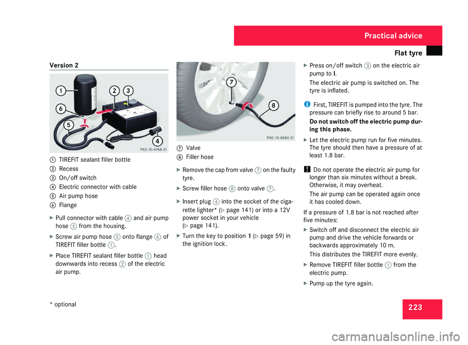
Version
2 1
TIREFIT sealant filler bottle
2 Recess
3 On/off switch
4 Electric connector with cable
5 Air pump hos e
6 Flange
X Pull connector with cable 4and air pump
hose 5from the housing.
X Screw air pump hose 5onto flange 6of
TIREFIT filler bottle 1.
X Place TIREFIT sealant filler bottle 1head
downwards into recess 2of the electric
air pump. 7
Valve
8 Filler hos e
X Remove the cap from valve 7on the faulty
tyre.
X Screw filler hose 8onto valve 7.
X Insert plug 4into the socket of the ciga-
rette lighter* (Y page 141) or into a 12V
power socket in your vehicle
( Y page 141).
X Turn the key to position 1(Y page 59) in
the ignition lock . X
Press on/off switch 3on the electric air
pump to I.
The electric air pump is switched on. The
tyre is inflated.
i First, TIREFIT is pumped into the tyre. The
pressure can briefly rise to around 5 bar.
Do not switch off the electric pump dur-
ing this phase .
X Let the electric pump run for five minutes.
The tyre should then have a pressure of at
least 1.8 bar.
! Do not operate the electric air pump for
longer than six minutes without a break.
Otherwise, it may overheat.
The air pump can be operated again once
it has cooled down.
If a pressure of 1.8 bar is not reached after
five minutes:
X Switch off and disconnect the electric ai r
pump and drive the vehicle forwards or
backwards approximately 10 m.
This distributes the TIREFIT more evenly.
X Remove TIREFIT filler bottle 1from the
electric pump .
X Pump up the tyre again. Practical advice
* optional
171_AKB; 3; 4, en-GB
vpfaff7
, 2007-11-13T10:50:25+01:00 - Seite 223