Page 60 of 317

Driving safet
ysystems 57
If yo
udeact ivate ESP ®
:
R ESP ®
no longe rimp roves driving stability.
R engine torque is no longe rlimit ed and the
drive wheels ar eabletos pin. Th espinning
wheels produce acutting effect for better
traction.
R tractio ncontrol is still activated.
R ESP ®
still provide ssuppo rt when yo ubrake
firmly.
i If ESP ®
is deactivate dand one or more
wheels start to spin, the vwarning lamp
in the instrumen tcluste rdoesn ot flash. In
such situations ESP ®
will not stabilise the
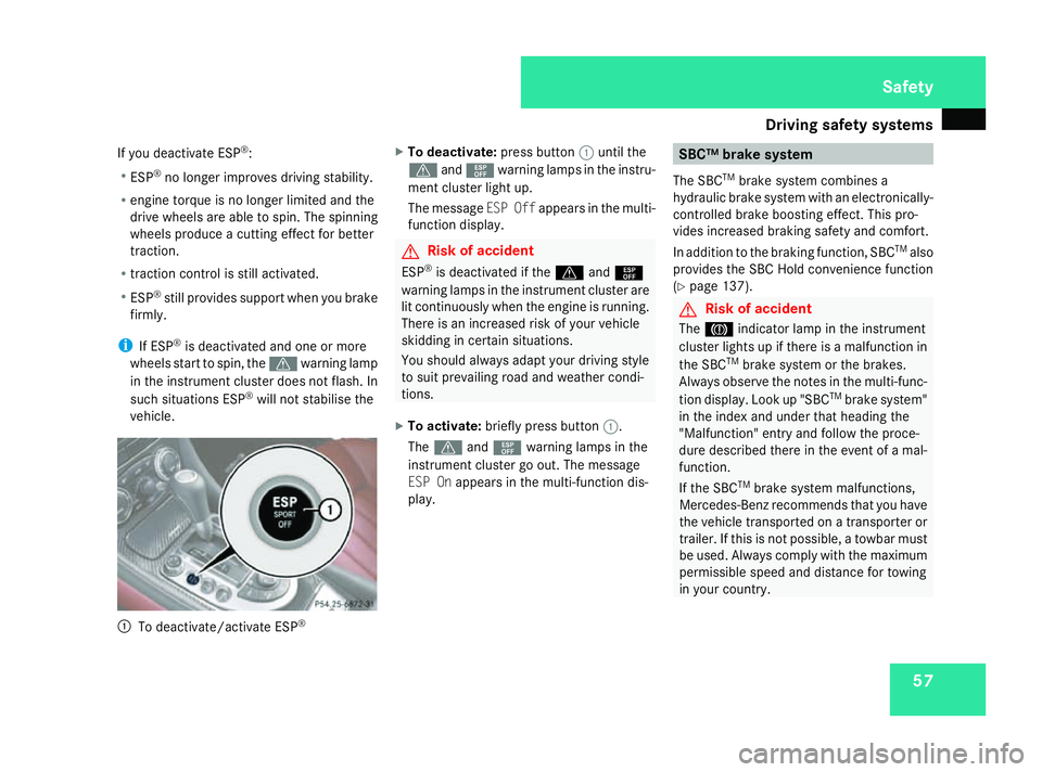
vehicle. 1
To deactivate/activat eESP® X
To deactivate: pressbutton 1untilt he
v and¯ warning lamp sinthe instr u-
ment cl usterlight up.
Th em essage ESPO ffappear sinthe multi-
function displa y. G
Risk of ac
cident
ESP ®
is deactivated if the vand¯
warning lamp sinthe instr umentclus tera re
li tc ontin uously when the engin eisrunning.
Ther eisani ncreased risk of yourvehicle
skiddin gincertain situations.
Yo us hould alwaysadap tyou rd riving style
to suit prevailing road an dweather condi-
tions.
X To activate: brieflypress button 1.
The v and¯ warning lamp sinthe
instr ument clus tergoo ut.T he message
ES POn appear sinthe multi-function dis-
play. SBC
™brake system
Th eS BCTM
brak esystemc ombines a
hydrauli cbrake syste mwithane lectronicall y-
controlled brak eboost inge ffec t. This pro-
vide sincreased brakin gsafet yand comfort.
In additio ntothe brakin gfun ction, SBC TM
also
provides the SBC Hold convenienc efunction
(Y page 137). G
Risk of ac
cident
The 3 indicator lamp in the instr ument
cl us terlight supift here isamalfun ction in
the SBC TM
brak esystemort he brakes.
Alwa ysobserve the note sinthe multi-func-
tio nd isplay. Lookup"SBC TM
brak esystem"
in the inde xand un dertha th eading the
"Malfunction" entry an dfollow the proce-
dure described there in the event of amal-
function.
If the SBC TM
brak esystemm alfun ctions,
Mercedes-Benz recommends tha tyou have
the vehicl etransported on atransporter or
trailer .Ifthisisn ot possible ,atowba rmust
be used. Alwayscompl ywitht he maxim um
permissible spee dand distance fo rtowing
in your country. Safety
230_AKB; 5; 4, en-GB
bjanott,
Version: 2.9.6
2008-04-08T15:09:54+02:00
-Seite 57 ZDateiname: 6515_3089_02_buchblock.pdf; preflight
Page 146 of 317

Driving sys
tems 143
Front sensors Centre Approximatel
y100 cm Corners Approximatel
y60cm Rea
rsenso rs Centre Approximatel
y120 cm Corners Approximatel
y80cm !
Payp articula rattentio ntoobjects above
or belo wthe sensors when parking, such
as flower pots or trailer towbars. Parktronic
does not detect such objects when the yare
in the immediate vicinity of the vehicle. You
could damage the vehicl eorthe objects.
Ultrasonic sources such as an automatic
ca rw ash, alorry's compressed-air brakes
or ap neumati cdrill could caus eParktronic
to malfunction.
Minimum distance Centre Approximatel
y20cm Corners Approximatel
y15cm If there is an obstacle withi
nthisr ange,all
warning displays ligh tupa nd atone sounds.
If the distance fall sbelow the minimum clear-
ance, it ma ynolongerbes hown.
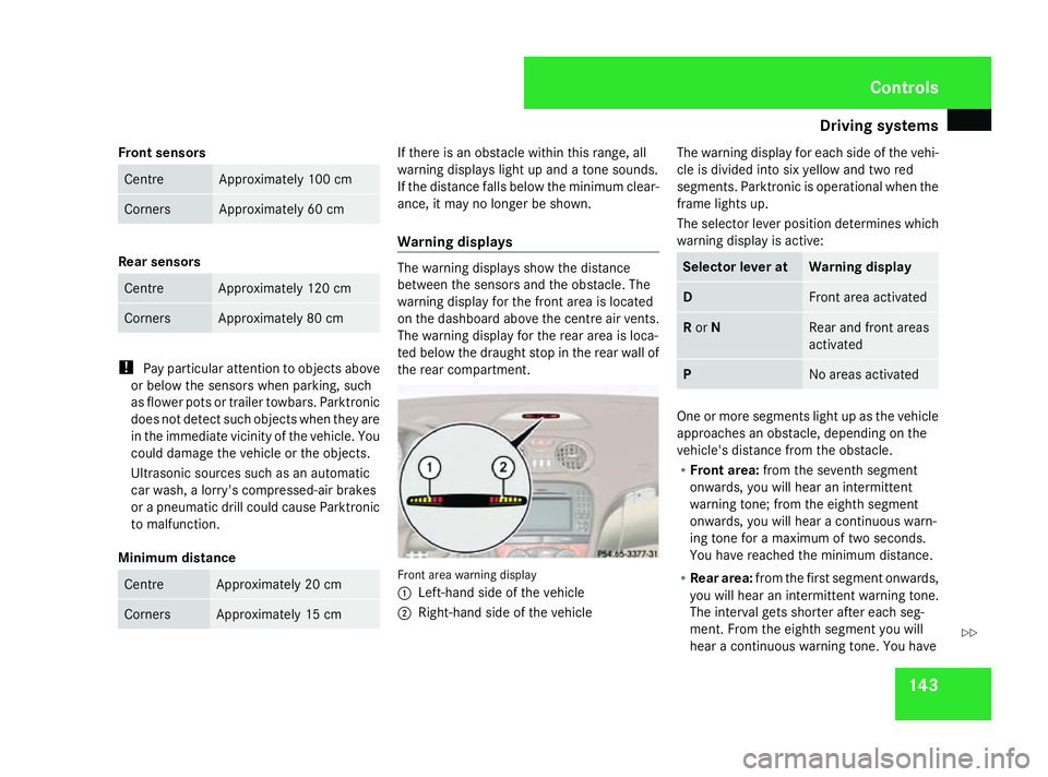
Warnin gdisplays Th
ew arning displays sho wthe distance
between the sensors and the obstacle .The
warning displa yfor the front area is located
on the dashboard above the centr eairvents.
Th ew arning displa yfor the rea rareaisl oca-
ted belo wthe draught sto pinthe rea rwallof
the rea rcompartment. Front area warning display
1
Left-hand side of the vehicle
2 Right-hand side of the vehicle Th
ew arning displa yfor each side of the vehi-
cle is divide dinto si xyello wand two red
segments. Parktronic is operational when the
frame lights up.
Th es elect or lever positio ndetermine swhich
warning displa yisactive: Selecto
rlever at Warnin
gdisplay D Front area activated
R
or N Rear and front areas
activated
P No area
sactivated One or mor
esegments ligh tupast he vehicle
approache sanobstacle ,depen ding on the
vehicle' sdistance fro mthe obstacle.
R Front area: fromt he seventh segment
onwards ,you will hear an intermittent
warning tone ;fro mt he eighth segment
onwards ,you will hear acontinuous warn-
ing tone for amaximum of two seconds.
Yo uh aver eache dthe minimum distance.
R Rea rarea: fromt he first segment onwards,
yo uw illh earani ntermittent warning tone.
Th einterva lgetss horter after each seg-
ment. Fro mthe eighth segment yo uwill
hear acontinuous warning tone .You have Controls
230_AKB; 5; 4, en-GB
bjanott,
Version: 2.9.6 2008-04-08T15:09:54+02:00-Seite 143 ZDateiname: 6515_3089_02_buchblock.pdf; preflight
Page 285 of 317

Towin
gand tow-starting 282
Opening the rea
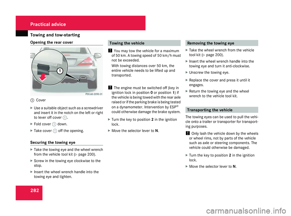
rcover 1
Cover
X Use asuitabl eobject such as ascrewdriver
and insert it in the notch on the left or right
to lever off cover 1.
X Fol dc over 1down.
X Take cover 1off the opening.
Securin gthe towin geye X
Take the towing ey eand the whee lwrench
fro mt he vehicl etoolkit ( Ypage 200).
X Scre wint he towing ey eclockwise to the
stop.
X Insert the whee lwrench handl einto the
towing ey eand tighten. Towin
gthe vehicle
! Youm aytow the vehicl efor am aximum
of 50 km. Atowing spee dof50k m/h must
not be exceeded.
With towing distances ove r50km, the
entire vehicl eneeds to be lifted up and
transported.
! Thee ngine must be switched off (ke yin
ignition lock in position 0or position 1)if
the vehicl eisbeing towed with the rea raxle
raised or if the parking brake is being tested
on adynamometer. Interventio nbyESP®
could otherwis edamag ethe brake system.
X Turn the key to position 2in the ignition
lock.
X Move the selector lever to N. Removing the towin
geye
X Take the whee lwrench fro mthe vehicle
too lkit ( Ypage 200).
X Insert the whee lwrench handl einto the
towing ey eand tur nitanti-clockwise.
X Unscrew the towing eye.
X Replac ethe cover and press it unti lit
engages.
X Retur nthe towing ey eand the wheel
wrench to the vehicl etoolkit. Transporting the vehicle
Th et owing eyes ca nbeusedtop ullt he vehi-
cle onto atrailer or transporte rfor transport-
ing purposes.
! Onlylas ht he vehicl edownbyt he wheels
or whee lrim s, not by parts of the vehicle
such as axl eorsteering components .The
vehicl ecould otherwis ebedamaged.
X Turn the key to position 2in the ignition
lock.
X Move the selector lever to N.Practical advice
230_AKB; 5; 4, en-GB
bjanott,
Version: 2.9.6 2008-04-08T15:09:54+02:00-Seite 282 Dateiname: 6515_3089_02_buchblock.pdf; preflight