Page 502 of 561
.
�Insert the SmartKey with
KEYLESS-GO* into the starter switch.
�Switch on the i")
501 Practical hints
Towing the vehicle
�Remove the KEYLESS-GO* start/stop
button from the starter switch
(
�page 41).
�Insert the SmartKey with
KEYLESS-GO* into the starter switch.
�Switch on the ignition.
�Depress the brake pedal.
�Shift the automatic transmission to
neutral positionN.
�Release the brake pedal.
�If engaged, release the parking brake
(
�page 57).
�Switch off the ignition and leave the
SmartKey with KEYLESS-GO* in the
starter switch.
Installing towing eye bolt
Depending on whether you are towing a
vehicle or you are being towed, the towing
eye bolt can be screwed into threaded
holes which are located behind covers on
the right-hand side of each bumper.
1Cover!Towing of the vehicle should only be done
using the properly installed towing eye bolt.
Never attach a tow cable, tow rope or tow rod to
the vehicle chassis, frame or suspension parts.
iTo signal turns while being towed with
hazard warning flasher in use, set the starter
switch to position2 and activate combination
switch for left or right turn signal in usual manner
– only the selected turn signal will operate.
Upon canceling the turn signal, the hazard warn-
ing flasher will operate again.
Page 503 of 561
502 Practical hints
Towing the vehicle
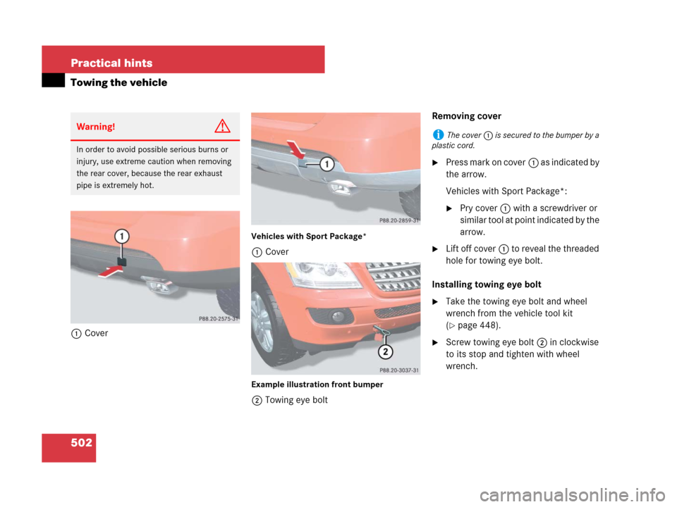
1Cover
Vehicles with Sport Package*
1Cover
Example illustration front bumper
2Towing eye boltRemoving cover
�Press mark on cover1 as indicated by
the arrow.
Vehicles with Sport Package*:
�Pry cover1 with a screwdriver or
similar tool at point indicated by the
arrow.
�Lift off cover1 to reveal the threaded
hole for towing eye bolt.
Installing towing eye bolt
�Take the towing eye bolt and wheel
wrench from the vehicle tool kit
(
�page 448).
�Screw towing eye bolt2 in clockwise
to its stop and tighten with wheel
wrench.
Warning!G
In order to avoid possible serious burns or
injury, use extreme caution when removing
the rear cover, because the rear exhaust
pipe is extremely hot.
iThe cover1 is secured to the bumper by a
plastic cord.
Page 504 of 561
503 Practical hints
Towing the vehicle
Removing towing eye bolt
�Loosen towing eye bolt2 counter-
clockwise with wheel wrench.
�Unscrew towing eye bolt2.
�Store the towing eye bolt and wheel
wrench back into the vehicle tool kit
(
�page 448).
Installing cover
�Engage cover1 at top and press at
bottom.
Stranded vehicle
Freeing a stranded vehicle, on which the
wheels are dug into sand or mud, should
be done with the greatest of care, especial-
ly if the vehicle is heavily loaded.
Avoid pulling the vehicle abruptly or diago-
nally, since it could result in damage to the
chassis alignment.
Never try to free a vehicle that is still cou-
pled to a trailer.
If possible, a vehicle equipped with trailer
hitch receiver should be pulled backward
in its own previously made tracks.
Page 505 of 561

504 Practical hints
Fuses
The electrical fuses in your vehicle serve to
switch off malfunctioning power circuits.
If a fuse is blown, the components and sys-
tems secured by that fuse will stop operat-
ing.If a newly inserted fuse blows again, have
the cause determined and rectified by an
authorized Mercedes-Benz Light Truck
Center.
A fuse chart explains the fuse allocation
and fuse amperages. It is located in the
cargo compartment with the vehicle tool
kit (
�page 448).
The electrical fuses are located in different
fuse boxes:
�Fuse box in engine compartment
(
�page 505)
�Fuse box in cargo compartment
(
�page 505)
�Fuse box in passenger compartment
(
�page 506)Before replacing fuses:
�Apply parking brake (�page 65).
�Make sure the automatic transmission
is set toP (
�page 185).
The gear position indicator in the multi-
function display should be on
P.
�Turn off all electrical consumers.
�Turn off the engine (�page 40).
�Remove the SmartKey from the starter
switch.
Vehicles with KEYLESS-GO*:
�Open the driver’s door (this puts
the starter switch in position0,
same as with the SmartKey re-
moved from the starter switch). The
driver’s door then can be closed
again.
Warning!G
Only use fuses approved by Mercedes-Benz
with the specified amperage for the system
in question and do not attempt to repair or
bridge a blown fuse. Using other than ap-
proved fuses or using repaired or bridged
fuses may cause an overload leading to a
fire, and/or cause damage to electrical
components and/or systems. Have the
cause determined and remedied by an au-
thorized Mercedes-Benz Light Truck Center.
iA blown fuse must be replaced by an appro-
priate spare fuse (recognizable by its color or the
fuse rating given on the fuse) of the amperage
recommended in the fuse chart. Any
Mercedes-Benz Light Truck Center will be glad to
advise you on this subject.
Page 506 of 561
505 Practical hints
Fuses
Fuse box in engine compartment
The fuse box is located on the passenger
side of the engine compartment.
�Open the hood (�page 341).
Example illustration fuse box ML 350
(ML 320 CDI, ML 550, ML 63 AMG similar)
1Fuse box cover
2Clamps
�Pull clamps2 in direction of arrow.
�Lift fuse box cover1 up.
�Install fuse box cover in reverse order.
�Close the hood after checking or
replacing fuses (
�page 343).
Fuse box in cargo compartment
The fuse box is located in the cargo com-
partment behind the passenger side trim
panel.
1Lock
2CoverRemoving/installing cover
�Open the tailgate (�page 119).
�Insert a suitable object such as a coin
into the slot of lock1 (
�page 505).
�Turn lock1 counterclockwise by 90°
in direction of arrow.
�Remove cover2.
�Install cover2 in reverse order.
!The fuse box cover must be installed
properly to prevent moisture and/or dirt from
entering the fuse box and possibly impairing fuse
operation.
Page 507 of 561

506 Practical hints
Fuses
Fuse box in passenger compartment
The fuse box is located behind a cover in
the dashboard on the front passenger side.
1CoverOpening
�Open the front passenger door.
�Open the glove box (�page 279).
�Insert flat, blunt object as a lever into
the edge of the cover1 at the position
indicated by the arrow.
�Loosen cover1 from dashboard using
lever.
�Using your hands, pull cover1 out
and remove.
Closing
�Hook cover1 into the opening at the
front.
�Press cover1 back on until it engag-
es.
Emergency engine shut-down
If the engine cannot be turned off as de-
scribed in the “Getting started” section
(
�page 66), you may use the following
emergency procedure.
�Take the fuse chart from the vehicle
tool kit (
�page 450).
�Open the fuse box in engine compart-
ment (
�page 505).
�Remove fuse 120.
Find its location in the fuse chart.
!Do not use sharp objects such as a screw-
driver to open the fuse box cover1 in the dash-
board, as this could damage the fuse box cover
or the dashboard.
Page 511 of 561
510 Technical data
Identification labels
1Certification label (on driver’s B-pillar)
The V
ehicle Identification Number (VIN)
can be found in the following locations:
�on the certification label
�embossed underneath the
passenger-side rear seat (
�page 511)
�on the lower edge of the windshield
(
�page 511)
Example certification label (U.S. vehicles)
2Paintwork code
3VIN
Example certification label
(Canada vehicles)
2Paintwork code
3VIN
iData shown on certification label are for
illustration purpose only. These data are specific
to each vehicle and may vary from data shown in
the illustration. Refer to certification label on
vehicle for actual data specific to your vehicle.
Page 512 of 561
511 Technical data
Identification labels
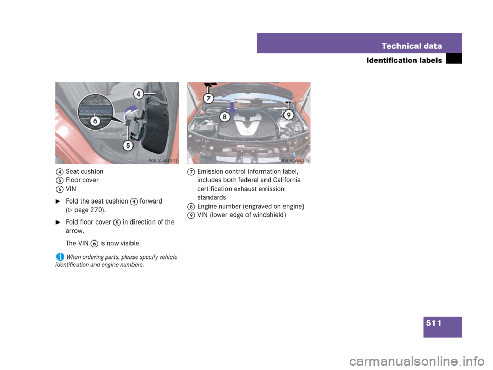
4Seat cushion
5Floor cover
6VIN
�Fold the seat cushion4 forward
(
�page 270).
�Fold floor cover5 in direction of the
arrow.
The VIN6 is now visible.7Emission control information label,
includes both federal and California
certification exhaust emission
standards
8Engine number (engraved on engine)
9VIN (lower edge of windshield)
iWhen ordering parts, please specify vehicle
identification and engine numbers.