Page 474 of 561
473 Practical hints
Replacing bulbs
License plate lamp
1License plate lamp cover
2Screws
�Loosen screws2.
�Remove license plate lamp cover1.
�Replace the tubular bulb.
�Reinstall license plate lamp cover1.
�Retighten screws2.
Adjusting headlamp aim
VVertical centerline
HHeadlamp mounting height, measured
from the centerCorrect headlamp adjustment is extremely
important. To check and readjust a head-
lamp, follow the steps described:
�Park the vehicle on a level surface
25 feet (7.6 m) from a vertical test
screen or wall.
�Switch the headlamps on
(
�page 135).
If the beam does not show a beam pattern
as indicated in the figure left, then follow
the steps below:
�Open hood (�page 341).
iHigh beam adjustments simultaneously aim
the low beam.
Vehicle should have a normal tailgate load.
��
Page 475 of 561
474 Practical hints
Replacing bulbs
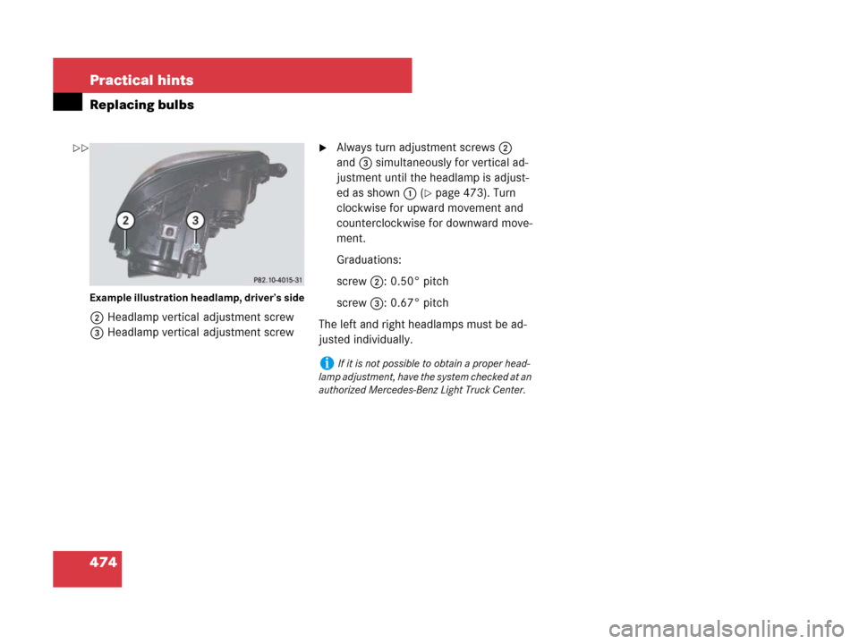
Example illustration headlamp, driver’s side
2Headlamp vertical adjustment screw
3Headlamp vertical adjustment screw
�Always turn adjustment screws2
and3 simultaneously for vertical ad-
justment until the headlamp is adjust-
ed as shown1 (
�page 473). Turn
clockwise for upward movement and
counterclockwise for downward move-
ment.
Graduations:
screw2: 0.50° pitch
screw3: 0.67° pitch
The left and right headlamps must be ad-
justed individually.
iIf it is not possible to obtain a proper head-
lamp adjustment, have the system checked at an
authorized Mercedes-Benz Light Truck Center.
��
Page 476 of 561

475 Practical hints
Replacing wiper blades
�Replacing wiper blades
Front wiper blades
Removing
�Remove the SmartKey from the starter
switch.
Vehicles with KEYLESS-GO*:
�Make sure the vehicle’s on-board
electronics have status0
(
�page 42).
�Fold the wiper arms forward until they
engage.
1Wiper blade
2Cover
3Attachment
4Tab
5Removing
�Press tabs4 together and tilt wiper
blade1 to detach tabs4 on both
recesses of attachment3.
Wiper blade1 is released on one end.
�Maintaining its tilted position, slide
wiper blade1 out of attachment3 in
direction of arrow5.
Warning!G
For safety reasons, switch off wipers and
remove SmartKey from starter switch
(vehicles with KEYLESS-GO*: Make sure the
vehicle’s on-board electronics have
status
0) before replacing a wiper blade.
Otherwise the motor could suddenly turn on
and cause injury.
Warning!G
Wiper blades are components that are sub-
ject to wear and tear. Replace the wiper
blades twice a year, preferably in the spring
and fall. Otherwise the windows will not be
properly wiped. As a result, you may not be
able to observe surrounding traffic condi-
tions and could cause an accident.
!Never open the hood when the wiper arms
are folded forward.
Hold on to the wiper when folding the wiper arm
back. If released, the force of the impact from
the tensioning spring could crack the windshield.
Do not allow the wiper arms to contact the wind-
shield glass without a wiper blade inserted.
Make sure the wiper blades are properly
installed. Improperly installed wiper blades may
cause windshield damage.
For your convenience, we recommend that you
have this work carried out by an authorized
Mercedes-Benz Light Truck Center.
!Do not pull on the wiper blade inserts. They
could tear.
Page 478 of 561
477 Practical hints
Replacing wiper blades
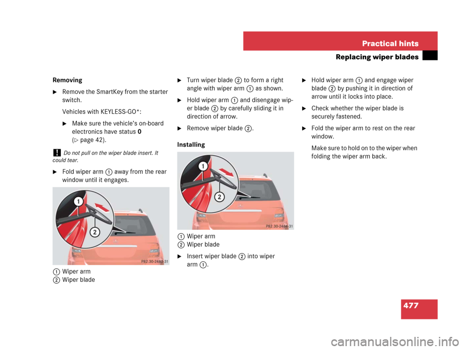
Removing
�Remove the SmartKey from the starter
switch.
Vehicles with KEYLESS-GO*:
�Make sure the vehicle’s on-board
electronics have status0
(
�page 42).
�Fold wiper arm1 away from the rear
window until it engages.
1Wiper arm
2Wiper blade
�Turn wiper blade2 to form a right
angle with wiper arm1 as shown.
�Hold wiper arm1 and disengage wip-
er blade2 by carefully sliding it in
direction of arrow.
�Remove wiper blade2.
Installing
1Wiper arm
2Wiper blade
�Insert wiper blade2 into wiper
arm1.
�Hold wiper arm1 and engage wiper
blade2 by pushing it in direction of
arrow until it locks into place.
�Check whether the wiper blade is
securely fastened.
�Fold the wiper arm to rest on the rear
window.
Make sure to hold on to the wiper when
folding the wiper arm back.
!Do not pull on the wiper blade insert. It
could tear.
Page 479 of 561
.
�Park the vehicle in a safe distance from
mov")
478 Practical hints
Flat tire
Preparing the vehicle
�Vehicles with air suspension program*:
Make sure the vehicle level is set to
highway (
�page 257).
�Park the vehicle in a safe distance from
moving traffic on a hard, flat surface
when possible.
�Turn on the hazard warning flasher
(
�page 141).
�Turn the steering wheel so that the
front wheels are in a straight-ahead
position.
�Set the parking brake (�page 57).
�Set the automatic transmission to park
positionP (
�page 185).
�Turn off the engine (�page 39).
�Have any passenger exit the vehicle at
a safe distance from the roadway.
�Vehicles with SmartKey: Remove the
SmartKey from the starter switch.
Vehicles with KEYLESS-GO*: Open the
driver’s door (this puts the starter
switch in position0, same as with the
SmartKey removed from the starter
switch). The driver’s door then can be
closed again.
�Remove the KEYLESS-GO*
start/stop button from the starter
switch.
Warning!G
The dimensions of the spare wheel
(Minispare wheel or collapsible tire) are dif-
ferent from those of the road wheels. As a
result, the vehicle handling characteristics
change when driving with a spare wheel
mounted. Adapt your driving style accord-
ingly.
The spare wheel is for temporary use only.
When driving with a spare wheel mounted,
ensure proper tire pressure and do not ex-
ceed a vehicle speed of 50 mph (80 km/h).
Drive to the nearest Mercedes-Benz Light
Truck Center as soon as possible to have the
spare wheel replaced with a regular road
wheel.
Never operate the vehicle with more than
one spare wheel mounted.
Do not switch off the ESP
® when a
Minispare wheel is mounted.
Warning!G
Vehicles with air suspension program*:
Do not open or close any doors or the
tailgate while mounting a spare wheel. The
vehicle could rise or lower to a previously
selected level. You or others could be
injured as a result.
iOpen door only when conditions are safe to
do so.
Page 480 of 561
.
Vehicles with Minispare wheel:
�Take the Minispare wheel out of the
cargo")
479 Practical hints
Flat tire
Mounting the spare wheel
Preparing the vehicle
�Prepare the vehicle as described
(
�page 478).
Vehicles with Minispare wheel:
�Take the Minispare wheel out of the
cargo compartment (
�page 453).
�Take the wheel wrench, the collapsible
wheel chock, and the vehicle jack out
of the cargo compartment
(
�page 448).
Vehicles with collapsible tire
(ML 63 AMG only):
�Take the collapsible tire, wheel wrench,
wheel bolts, jack, and electric air pump
out of the cargo compartment
(
�page 454).Lifting the vehicle
iVehicles with collapsible tire (ML 63 AMG
only):
You can use the power outlets, except for the
power outlet in the front center console, to
operate the electric air pump even when the
ignition is switched off, e.g. in order to inflate the
collapsible emergency spare tire (
�page 485).
An emergency shut-off feature ensures that the
vehicle’s electrical voltage does not fall below a
minimum level. If the voltage drops to this mini-
mum level, the power outlets are automatically
switched off. This ensures that enough power re-
mains to start the engine.
!Depending on vehicle production date your
vehicle may be equipped with a scissors-type
jack (located under the cargo compartment
floor). If so equipped, only use this jack when
jacking up the vehicle as otherwise the vehicle’s
underbody can be damaged. See separate
instructions for scissors-type jack.
Warning!G
When jacking up the vehicle, only use the
jack which has been specifically approved
by Mercedes-Benz for your vehicle.
The jack is designed exclusively for jacking
up the vehicle at the jack take-up brackets
built into both sides of the vehicle. Make
sure the jack arm is fully seated in the jack
take-up bracket.
The jack is intended only for lifting the
vehicle briefly for wheel changes. It is not
suited for performing maintenance work
under the vehicle. To help avoid personal in-
jury, use the jack only to lift the vehicle dur-
ing a wheel change.
Never get beneath the vehicle while it is sup-
ported by the jack. Keep hands and feet
away from the area under the lifted vehicle.
Always lower the vehicle onto sufficient
capacity jackstands before working under
the vehicle.
��
Page 481 of 561

480 Practical hints
Flat tire
�Prevent the vehicle from rolling away
by blocking wheels with wheel chocks
or other sizeable objects.One collapsible wheel chock is includ-
ed with the vehicle tool kit
(
�page 448). For information on set-
ting up the collapsible wheel chock,
see (
�page 452).
Changing wheel on a level surface
Changing rear wheel on passenger side
(Example illustration)
�Place the wheel chock in front of and
another sizeable object behind the
wheel that is diagonally opposite to the
wheel being changed.
Changing wheel on a slight decline
Always try lifting the vehicle using the jack
on a level surface. However, should
circumstances require you to do so on a
slight decline, place the wheel chock and
another sizeable object as follows:
Changing wheel on passenger side
(Example illustration)
Always firmly set parking brake and block
wheels with wheel chocks or other sizeable
objects before raising vehicle with jack. Do
not disengage parking brake while the vehi-
cle is raised.
Make sure that the ground on which the ve-
hicle is standing and where you place the
jack is solid, level and not slippery. If neces-
sary, use a large underlay. On slippery sur-
faces, such as tiled floors, you should use a
non-slip underlay, for example a rubber mat.
Do not use wooden blocks or similar objects
to support the jack. Otherwise the jack may
not be able to achieve its load-bearing ca-
pacity if it is not at its full height.
Never start the engine when the vehicle is
raised.
Also observe the notes on the jack.
Warning!G
Only jack up the vehicle on level ground or
on slight inclines/declines. Otherwise, the
vehicle could fall off the jack and injure you
or others.
��
Page 483 of 561
.
Screw-t")
482 Practical hints
Flat tire
Depending on production date, your vehi-
cle may be equipped with either a
screw-type vehicle jack or a scissors-type
jack, see “Vehicle jack” (
�page 450).
Screw-type jack
2Take-up bracket
3Jack
4Crank
Scissors-type jack
2Take-up bracket
3Jack
4Ratchet
�Vehicles with scissors-type jack:
Attach reversible ratchet4 to vehicle
jack in such a way that the wordUP
can be seen.
�Place jack3 on firm ground.
�Position jack3 under the take-up
bracket2 so that it is always vertical
(plumb-line) as seen from the side,
even if the vehicle is parked on an
incline.
Warning!G
The jack is designed exclusively for
jacking up the vehicle at the jack take-up
brackets. Make sure the jack arm is fully
seated in the jack take-up bracket.
If you do not position the jack correctly in
the jack take-up bracket, the vehicle can:
�fall off the jack
�seriously or fatally injure you or others
!Do not position the jack on the body of the
vehicle, as this may cause damage to the
vehicle.
!Depending on vehicle production date your
vehicle may be equipped with a scissors-type
jack (located under the cargo compartment
floor). If so equipped, only use this jack when
jacking up the vehicle as otherwise the vehicle’s
underbody can be damaged. See separate
instructions for scissors-type jack.