Page 149 of 457
148 Controls in detail
Control system
The table below shows what settings can
be changed within the various menus.
Detailed instructions on making individual
settings can be found on the following
pages.
Instrument clusterLightingVehicleConvenience
(�page 149)(�page 151)(�page 154)(�page 156)
Selecting speedometer
display modeSetting daytime
running lamp mode
(USA only)Selecting audio search
functionActivating
easy-entry/exit feature
Selecting languageSetting locator lightingSetting automatic
locking
Selecting display
(digital speedometer or
outside temperature)
for status indicatorSetting night security
illumination
Setting interior lighting
delayed shut-off
W463.boo Seite 148 Montag, 19. November 2007 8:41 08
Page 152 of 457
151
Controls in detail
Control system
Lighting submenu
Access the
Lighting submenu via the
Settings menu. Use the Lighting
submenu to change the lamp and lighting
settings on your vehicle.
The following functions are available:
Setting daytime running lamp mode
(USA only)
�Move the selection marker with
button
æ orç to the
Lighting
submenu.
�Press button j ork repeatedly
until the message
Headlamp mode
appears in the multifunction display.
The selection marker is on the current
setting.
�Press button æ orç to select
manual operation (
Manual) or daytime
running lamp mode (
Constant).
With daytime running lamp mode activated
and the exterior lamp switch in
position M orU , the low beam
headlamps are switched on when the
engine is running.
In low ambient light conditions the
following lamps will switch on additionally:
�Parking lamps
�Tail lamps
�License plate lamps
�Side marker lamps
FunctionPage
Setting daytime running lamp
mode (USA only)151
Setting locator lighting152
Setting night security
illumination153
Setting interior lighting delayed
shut-off154
iCanada vehicles:
This function is not available as the daytime
running lamp mode is mandatory and therefore
in a constant mode.
W463.boo Seite 151 Montag, 19 . November 2007 8:41 08
Page 154 of 457
153
Controls in detail
Control system
Setting night security illumination
(Headlamps delayed shut-off)
Use this function to set whether you would
like the exterior lamps to remain on for
15 seconds during darkness after exiting
the vehicle and closing all doors.
With the headlamps delayed shut-off
feature activated and the exterior lamp
switch in position
U before the engine
is turned off, the following lamps will
switch on when the engine is turned off:
�Parking lamps
�Tail lamps
�License plate lamps
�Side marker lamps
�Front fog lamps
If after turning off the engine you do not
open a door or do not close an opened
door, the lamps will automatically switch
off after approxim ately 60 seconds.
�Move the selection marker with
buttonæ orç to the
Lighting
submenu.
�Press button j ork repeatedly
until the message
Headl. delayed
shut-off
appears in the multifunction
display.
The selection marker is on the current
setting.
�Press button æ orç to switch
the headlamps delayed shut-off feature
On or Off.
�Turn the exterior lamp switch to
position U before turning off the
engine.
The headlamps delayed shut-off
feature is activated.
You can temporarily deactivate the
headlamps delayed shut-off feature:
�Before exiting the vehicle, turn the
SmartKey in the starter switch to
position 0.
�Then turn it to position 2 and back to
position 0.
The headlamps delayed shut-off
feature is deactivated. It will reactivate
as soon as you reinsert the SmartKey in
the starter switch.
W463.boo Seite 153 Montag, 19 . November 2007 8:41 08
Page 165 of 457
164 Controls in detail
Automatic transmission
Gear selector lever positions
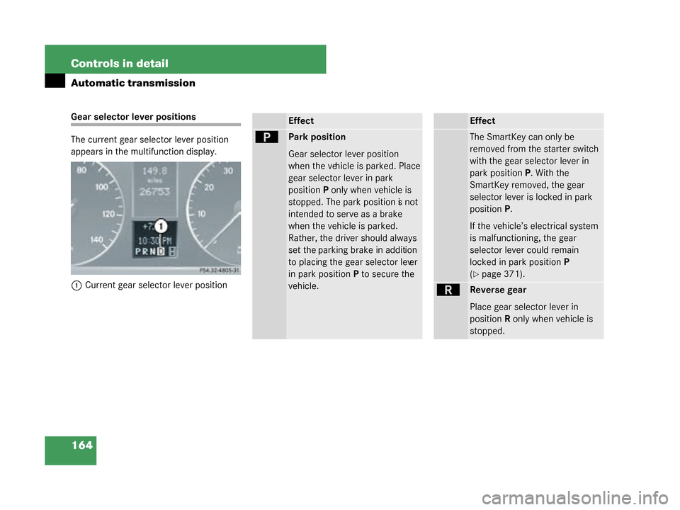
The current gear selector lever position
appears in the multifunction display.1 Current gear selector lever positionEffect
ìPark position
Gear selector lever position
when the vehicle is parked. Place
gear selector lever in park
position P only when vehicle is
stopped. The park position is not
intended to serve as a brake
when the vehicle is parked.
Rather, the driver should always
set the parking brake in addition
to placing the gear selector lever
in park position P to secure the
vehicle.
Effect
The SmartKey can only be
removed from the starter switch
with the gear selector lever in
park position P. With the
SmartKey removed, the gear
selector lever is locked in park
position P.
If the vehicle’s electrical system
is malfunctioning, the gear
selector lever could remain
locked in park position P
(
�page 371).
íReverse gear
Place gear selector lever in
position R only when vehicle is
stopped.
W463.boo Seite 164 Montag, 19 . November 2007 8:41 08
Page 208 of 457
207
Controls in detail
Loading
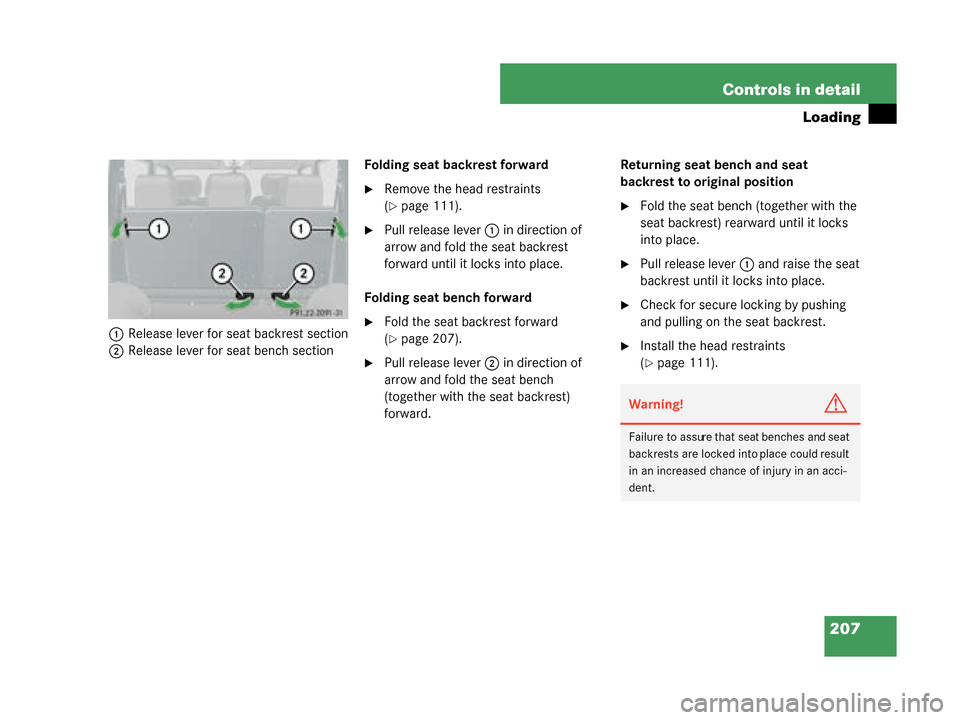
1
Release lever for seat backrest section
2 Release lever for seat bench section Folding seat backrest forward
�Remove the head restraints
(
�page 111).
�Pull release lever
1 in direction of
arrow and fold the seat backrest
forward until it locks into place.
Folding seat bench forward
�Fold the seat backrest forward
(
�page 207).
�Pull release lever 2 in direction of
arrow and fold the seat bench
(together with the seat backrest)
forward. Returning seat bench and seat
backrest to original position
�Fold the seat bench (together with the
seat backrest) rearward until it locks
into place.
�Pull release lever
1 and raise the seat
backrest until it locks into place.
�Check for secure locking by pushing
and pulling on the seat backrest.
�Install the head restraints
(
�page 111).
Warning!G
Failure to assure that seat benches and seat
backrests are locked into place could result
in an increased chance of injury in an acci-
dent.
W463.boo Seite 207 Montag, 19 . November 2007 8:41 08
Page 209 of 457
208 Controls in detail
Loading
Loading instructions
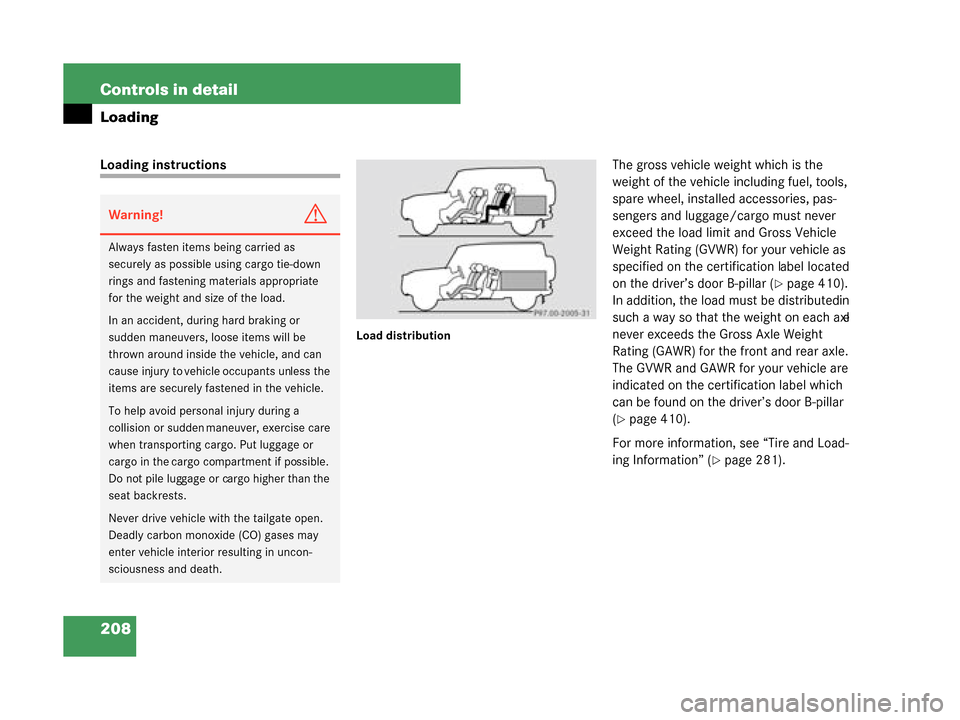
Load distribution
The gross vehicle weight which is the
weight of the vehicle including fuel, tools,
spare wheel, installed accessories, pas-
sengers and luggage/cargo must never
exceed the load limit and Gross Vehicle
Weight Rating (GVWR) for your vehicle as
specified on the certification label located
on the driver’s door B-pillar (
�page 410).
In addition, the load must be distributed in
such a way so that the weight on each axle
never exceeds the Gross Axle Weight
Rating (GAWR) for the front and rear axle.
The GVWR and GAWR for your vehicle are
indicated on the certification label which
can be found on the driver’s door B-pillar
(
�page 410).
For more information, see “Tire and Load-
ing Information” (
�page 281).
Warning!G
Always fasten items being carried as
securely as possible using cargo tie-down
rings and fastening materials appropriate
for the weight and size of the load.
In an accident, during hard braking or
sudden maneuvers, loose items will be
thrown around inside the vehicle, and can
cause injury to vehicl e occupants unless the
items are securely fastened in the vehicle.
To help avoid person al injury during a
collision or sudden maneuver, exercise care
when transporting cargo. Put luggage or
cargo in the cargo compartment if possible.
Do not pile luggage or cargo higher than the
seat backrests.
Never drive vehicle with the tailgate open.
Deadly carbon monoxide (CO) gases may
enter vehicle interior resulting in uncon-
sciousness and death.
W463.boo Seite 208 Montag, 19 . November 2007 8:41 08
Page 210 of 457
209
Controls in detail
Loading
The handling characteristics of a fully
loaded vehicle depend greatly on the load
distribution. It is therefore recommended
to load the vehicle according to the illustra-
tions shown, with the heaviest items being
placed towards the front of the vehicle.
Please pay attention to and comply with
the following instructions when loading the
vehicle and transporting cargo:
�Always place items being carried
against front or rear seat backrests,
and fasten them as securely as
possible.
�The heaviest portion of the cargo
should always be kept as low as possi-
ble against front or rear seat backrests.
�Always pad off sharp edges.
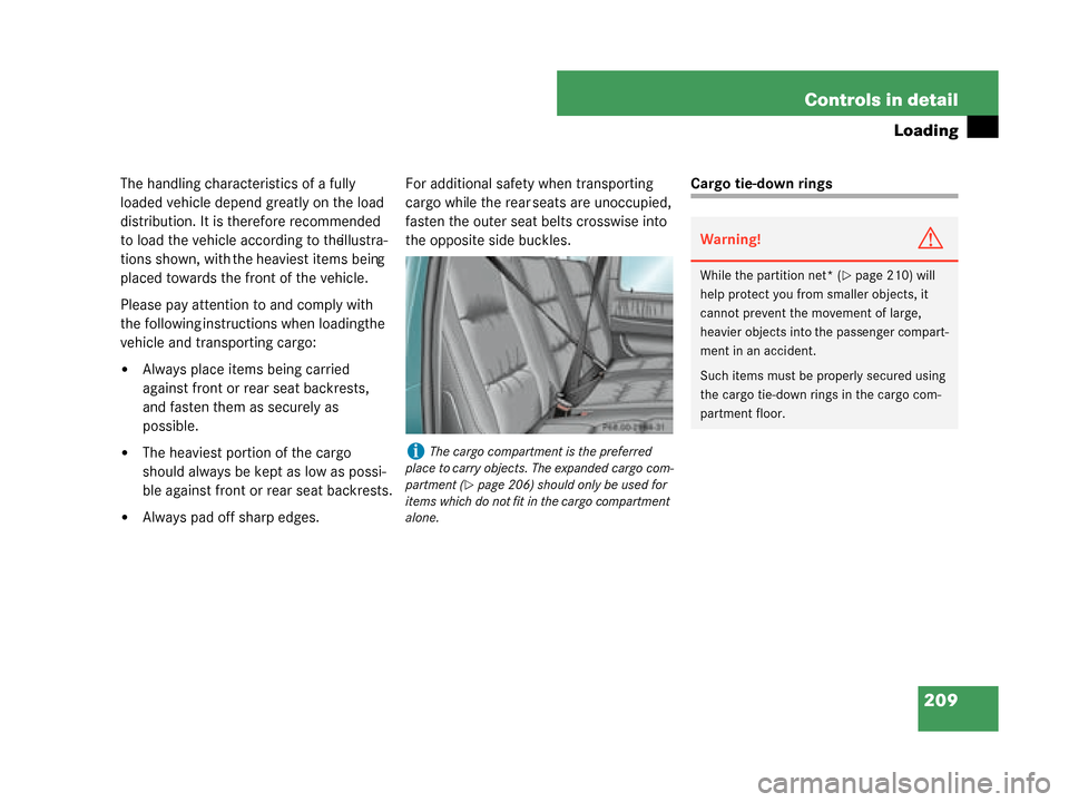
For additional safety when transporting
cargo while the rear seats are unoccupied,
fasten the outer seat belts crosswise into
the opposite side buckles.
Cargo tie-down rings
iThe cargo compartment is the preferred
place to carry objects. The expanded cargo com-
partment (
�page 206) should only be used for
items which do not fit in the cargo compartment
alone.
Warning!G
While the partition net* (�page 210) will
help protect you from smaller objects, it
cannot prevent the movement of large,
heavier objects into the passenger compart-
ment in an accident.
Such items must be properly secured using
the cargo tie-down rings in the cargo com-
partment floor.
W463.boo Seite 209 Montag, 19 . November 2007 8:41 08
Page 211 of 457
210 Controls in detail
Loading
Your vehicle is equipped with four cargo
tie-down rings located in the cargo com-
partment floor.1 Cargo tie-down rings Carefully secure cargo by applying even
load on all cargo tie-down rings with rope
of sufficient strength to hold down the
cargo.Partition net* (MB Accessory)
Warning!G
Make sure the partition net is properly
engaged at top and bottom position and the
tightening belts are securely fastened.
Never use a damaged partition net.
To help avoid personal
injury from smaller
objects being thrown around in the occu-
pant compartment during a collision or
sudden maneuver, always use partition net
when transporting cargo.
The partition net cannot prevent the move-
ment of large, heavier objects into the pas-
senger compartment in an accident. Such
items must be properly secured using the
cargo tie-down rings (
�page 209) in the
cargo compartment floor.
W463.boo Seite 210 Montag, 19 . November 2007 8:41 08