2008 MERCEDES-BENZ E-CLASS ESTATE wheel bolts
[x] Cancel search: wheel boltsPage 18 of 401
15
Tyre pressures
Table . . . . . . . . . . . . . . . . . . . . . . .356
Tyres
Direction of rotatio n.. . . . . . . . . . .229
General notes . . . . . . . . . . . . . . . . .227
Technical data . . . . . . . . . . . . . . . .357
Tyre tread . . . . . . . . . . . . . . . . . . . . . .229 U
Unit for distance Setting (on-board computer) . . . . .133
Unladen weight
. . . . . . . . . . . . . .369, 370, 372, 373, 374
Unlocking Emergency unlocking . . . . . . . . . . .306
From the inside (central unlocking
button) . . . . . . . . . . . . . . . . . . . . . . .70
Up (display message) . . . . . . . . . . ..126 V
Variable Speedtronic . . . . . . . . . . . ..152
Vehicle Emergency unlocking . . . . . . .306, 307
Individual settings (on-board com-
puter) . . . . . . . . . . . . . . . . . . . . . . .131
Leaving parked up . . . . . . . . . . . . .305
Towing . . . . . . . . . . . . . . . . . . . . . .339
Tow-starting . . . . . . . . . . . . . . . . . .339
Transporting . . . . . . . . . . . . . . . . . .340 Vehicle battery
. . . . . . . . . . . . . . . . .329
Vehicle dimensions . . . . . . . . . . . . ..366
Vehicle electronics . . . . . . . . . . . . ..345
Vehicle identification number
(VIN) . . . . . . . . . . . . . . . . . . . . . .346, 347
Vehicle identification plates . . . . ..346
Vehicle level Display message . . . . . . . . . . . . . .267
Setting (AIRMATIC DC) . . . . . . . . .156
Vehicle tool kit . . . . . . . . . . . . . . . . . .254
Vehicle weights . . . . . . . . . . . . . . . . .369 W
Warning and indicator lamp ABS (yellow) . . . . . . . . . . . . . . . . . .285
LIM (Cruise control) . . . . . . . . . . . .143
LIM (Distronic) . . . . . . . . . . . . . . . .146
LIM (variable Speedtronic) . . . . . . .152
Warning signal
Audible . . . . . . . . . . . . . . . . . . . . . .292
Warning triangle . . . . . . . . . . . . . . . .252
Washer fluid Display message . . . . . . . . . . . . . .281
Wearing seat belts . . . . . . . . . . . . . . ..95
Wheel bolts Tightening torque . . . . . . . . . . . . . .327
Wheel chock
Use . . . . . . . . . . . . . . . . . . . . . . . . .256 Wheels
General notes . . . . . . . . . . . . . . . . .227
Interchanging . . . . . . . . . . . . . . . . .233
Technical data . . . . . . . . . . . . . . . .357
Windowbags . . . . . . . . . . . . . . . . . . . . .46
Windows Cleaning . . . . . . . . . . . . . . . . . . . . .246
Cleaning the windscreen . . . . . . . .246
Side windows . . . . . . . . . . . . . . . . .107
Windscreen
Cleaning . . . . . . . . . . . . . . . . . . . . .246
Infrared reflecting . . . . . . . . . . . . .214
Windscreen washer fluid . . . . . . . ..390
Topping up . . . . . . . . . . . . . . . . . . .226
Windscreen washer fluid reservoir
. . . . . . . . . . . . . . . . . . . . . . . . . .226, 390
Windscreen washer reservoir Capacity . . . . . . . . . . . . . . . . . . . . .390
Windscreen washer system . . . . . ..390
Windscreen wipers . . . . . . . . . . . . ..105
Cleaning . . . . . . . . . . . . . . . . . . . . .246
Malfunction . . . . . . . . . . . . . . . . . .299
Replacing the wiper blades . . . . . .315
Winter diesel . . . . . . . . . . . . . . . . . . .221
Winter driving . . . . . . . . . . . . . .234, 235
Winter tyres . . . . . . . . . . . . . . . . . . . .234
Limiting the speed (on-board com-
puter) . . . . . . . . . . . . . . . . . . . . . . .154 Index
211_AKB; 2; 5, en-GB
mkalafa,
Version: 2.9.4
2008-02-29T16:57:07+01:00 - Seite 15 Dateiname: 6515_3416_02_buchblock.pdf; preflight
Page 236 of 401
Tyres and wheels
233
Restarting the tyre pressure monitor In most cases, the tyre pressure monitor will
automatically detect the new reference val-
ues, e.g. if you have:
R
changed the tyre pressure
R changed the wheels or tyres
R fitted new wheels or tyres
If you wish to define the new reference values
manually:
X Use the table on the inside of the fuel filler
flap to ensure that the tyre pressure is set
correctly in all four tyres for the current
operating conditions.
Also observe the notes in the section on
tyre pressures (Y page 229).
X Make sure that the key is in position 2in
the ignition lock.
The standard display appears in the multi-
function display (Y page 125).
X Press the jork button to select the
Tyre pressure function or wait until the
following message appears:
Tyre pressure displayed only after
driving for a few minutes X
Press the reset button on the left of the
instrument cluster (Y page 243).
The following message appears in the
multi-function display: Check current
tyre pressure?
X Press the æbutton.
The following message appears in the
multi-function display:
Tyre pressure monitor restarted
The tyre pressure monitor has stored the
pressure of the tyres as a new reference
value.
If you wish to cancel the restart:
X Press the çbutton. Interchanging the wheels
G
Risk of accident
Interchange the front and rear wheels only
if they have the same dimensions: for exam-
ple size, offset, etc.
After every wheel interchange/change,
have the tightening torque checked at a
qualified specialist workshop that has the
necessary specialist knowledge and tools
to carry out the work required. Mercedes- Benz recommends that you use a
Mercedes-Benz Service Centre for this pur-
pose. In particular, work relevant to safety
or on safety-related systems must be car-
ried out at a qualified specialist workshop.
The wheels could work loose if they are not
tightened to a torque of 130 Nm.
For safety reasons, Mercedes-Benz recom-
mends that you only use wheel bolts of the
correct size which have been approved for
Mercedes-Benz vehicles.
The wheels may be interchanged every
5,000 km to 10,000 km depending on the
degree of tyre wear, provided that the vehicle
has the same size front and rear tyres. Do not
reverse the direction of tyre rotation.
The wear patterns on the front and rear tyres
differ depending on the operating conditions.
Interchange the wheels before a clear wear
pattern has formed on the tyres. The front
tyres typically wear more on the shoulders
and the rear tyres in the centre.
Clean the contact surfaces of the wheel and
the brake disc thoroughly every time a wheel
is interchanged. Check the tyre pressure and,
if necessary, restart the tyre pressure loss
warning system or the tyre pressure moni-
tor*. Operation
* optional
211_AKB; 2; 5, en-GB
mkalafa
,V ersion: 2.9.4
2008-02-29T16:57:07+01:00 - Seite 233 ZDateiname: 6515_3416_02_buchblock.pdf; preflight
Page 259 of 401
Where will I find...?
256
Removing the "Minispare" emergency
spare wheel*/collapsible emergency
spare wheel or spare wheel*
X Saloon: remove the luggage well
(Y page 256).
X Estate: remove the luggage compartment
floor (Y page 194).
X Turn fastening element 3anti-clockwise.
X Remove the "Minispare" emergency spare
wheel/collapsible emergency spare wheel
or the spare wheel 2.
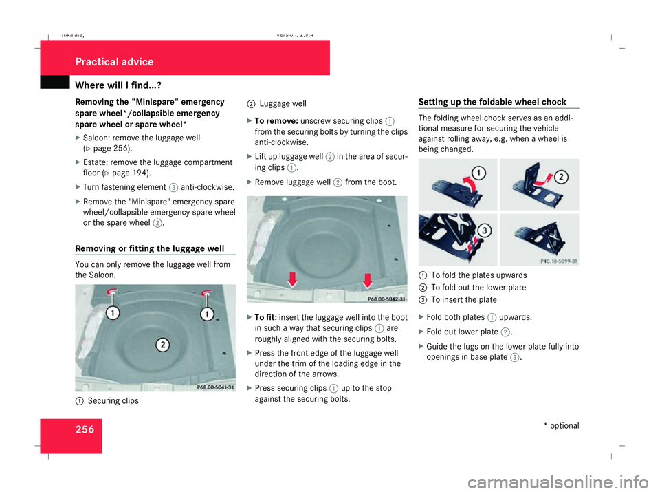
Removing or fitting the luggage well You can only remove the luggage well from
the Saloon. 1
Securing clips 2
Luggage well
X To remove: unscrew securing clips 1
from the securing bolts by turning the clips
anti-clockwise.
X Lift up luggage well 2in the area of secur-
ing clips 1.
X Remove luggage well 2from the boot. X
To fit: insert the luggage well into the boot
in such a way that securing clips 1are
roughly aligned with the securing bolts.
X Press the front edge of the luggage well
under the trim of the loading edge in the
direction of the arrows.
X Press securing clips 1up to the stop
against the securing bolts. Setting up the foldable wheel chock The folding wheel chock serves as an addi-
tional measure for securing the vehicle
against rolling away, e.g. when a wheel is
being changed.
1
To fold the plates upwards
2 To fold out the lower plate
3 To insert the plate
X Fold both plates 1upwards.
X Fold out lower plate 2.
X Guide the lugs on the lower plate fully into
openings in base plate 3.Practical advice
* optional
211_AKB; 2; 5, en-GB
mkalafa,
Version: 2.9.4 2008-02-29T16:57:07+01:00 - Seite 256Dateiname: 6515_3416_02_buchblock.pdf; preflight
Page 327 of 401

Flat tyre
324 required. Mercedes-Benz recommends
that you use a Mercedes-Benz Service
Centre for this purpose. In particular, work
relevant to safety or on safety-related sys-
tems must be carried out at a qualified
specialist workshop.
Preparing the vehicle X
Prepare the vehicle as described
(Y page 317).
X If a trailer is coupled, uncouple it.
X Place the wheels in the straight-ahead posi-
tion.
X Take out the following from the stowage
area beneath the boot/luggage compart-
ment floor:
R the "Minispare"/collapsible emergency
spare wheel* or the spare wheel*
R the vehicle tool kit
R the wheel chock
R the jack
X Secure the vehicle to prevent it from rolling
away.
On level ground: place chocks or similar
under the front and rear of the wheel that is diagonally opposite the wheel you wish
to change.
X On downhill gradients: place chocks or
similar under both wheels of the other axle.
Raising the vehicle 1
Wheel wrench
X Using wheel wrench 1, loosen the bolts on
the wheel you wish to change by about one
full turn. Do not unscrew the bolts com-
pletely. G
Risk of accident
If you fail to position the jack correctly, the
vehicle may: R
slip off the jack
R injure you or others
R be damaged
It is thus important to ensure that the jack
is positioned correctly in the respective
jacking points. Before positioning the jack,
remove any dirt that may have collected in
the jacking points.
The jacking points for the jack are located
behind the wheel housings of the front wheels
and in front of the wheel housings of the rear
wheels. 1
Jacking point
2 Jack
3 Crank
X Position jack 2at jacking point 1. Practical advice
* optional
211_AKB; 2; 5, en-GB
mkalafa,
Version: 2.9.4 2008-02-29T16:57:07+01:00 - Seite 324Dateiname: 6515_3416_02_buchblock.pdf; preflight
Page 328 of 401
Flat tyre
325X
Make sure that the base of the jack is posi-
tioned directly under jacking point 1.
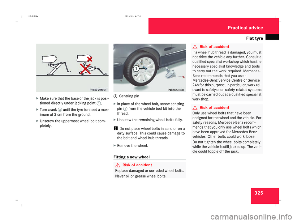
X Turn crank 3until the tyre is raised a max-
imum of 3 cm from the ground.
X Unscrew the uppermost wheel bolt com-
pletely. 1
Centring pin
X In place of the wheel bolt, screw centring
pin 1from the vehicle tool kit into the
thread.
X Unscrew the remaining wheel bolts fully.
! Do not place wheel bolts in sand or on a
dirty surface. This could cause damage to
the bolt and wheel hub threads.
X Remove the wheel.
Fitting a new wheel G
Risk of accident
Replace damaged or corroded wheel bolts.
Never oil or grease wheel bolts. G
Risk of accident
If a wheel hub thread is damaged, you must
not drive the vehicle any further. Consult a
qualified specialist workshop which has the
necessary specialist knowledge and tools
to carry out the work required. Mercedes-
Benz recommends that you use a
Mercedes-Benz Service Centre or Service
24h for this purpose. In particular, work rel-
evant to safety or on safety-related systems
must be carried out at a qualified specialist
workshop. G
Risk of accident
Only use wheel bolts that have been
designed for the wheel and the vehicle. For
safety reasons, Mercedes-Benz recom-
mends that you only use wheel bolts which
have been approved for Mercedes-Benz
vehicles. Other bolts could work loose.
Do not tighten the wheel bolts completely
while the vehicle is still jacked up. The vehi-
cle could topple off the jack. Practical advice
211_AKB; 2; 5, en-GB
mkalafa,
Version: 2.9.4 2008-02-29T16:57:07+01:00 - Seite 325 ZDateiname: 6515_3416_02_buchblock.pdf; preflight
Page 329 of 401
Flat tyre
3261
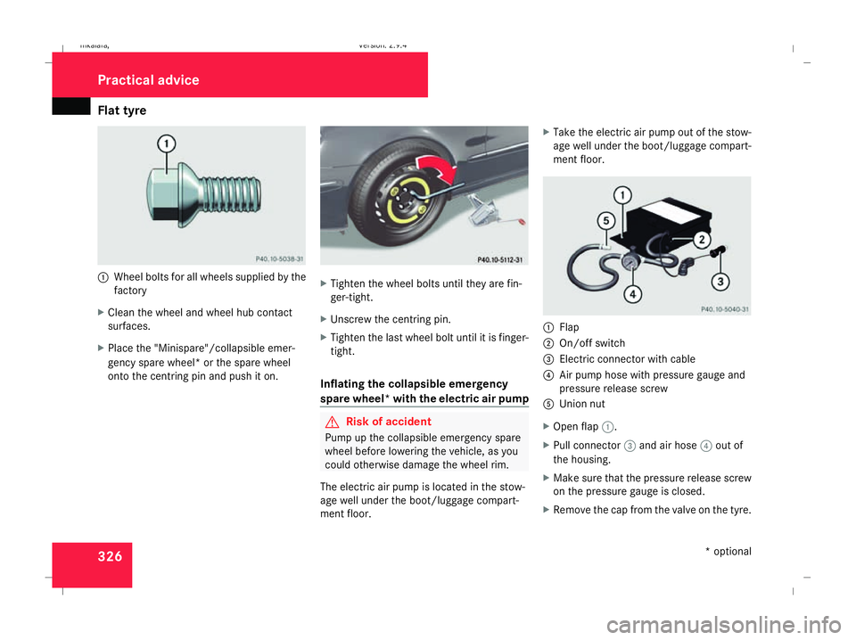
Wheel bolts for all wheels supplied by the
factory
X Clean the wheel and wheel hub contact
surfaces.
X Place the "Minispare"/collapsible emer-
gency spare wheel* or the spare wheel
onto the centring pin and push it on. X
Tighten the wheel bolts until they are fin-
ger-tight.
X Unscrew the centring pin.
X Tighten the last wheel bolt until it is finger-
tight.
Inflating the collapsible emergency
spare wheel* with the electric air pump G
Risk of accident
Pump up the collapsible emergency spare
wheel before lowering the vehicle, as you
could otherwise damage the wheel rim.
The electric air pump is located in the stow-
age well under the boot/luggage compart-
ment floor. X
Take the electric air pump out of the stow-
age well under the boot/luggage compart-
ment floor. 1
Flap
2 On/off switch
3 Electric connector with cable
4 Air pump hose with pressure gauge and
pressure release screw
5 Union nut
X Open flap 1.
X Pull connector 3and air hose 4out of
the housing.
X Make sure that the pressure release screw
on the pressure gauge is closed.
X Remove the cap from the valve on the tyre. Practical advice
* optional
211_AKB; 2; 5, en-GB
mkalafa,
Version: 2.9.4 2008-02-29T16:57:07+01:00 - Seite 326Dateiname: 6515_3416_02_buchblock.pdf; preflight
Page 330 of 401
Flat tyre
327
X
Screw union nut 5on air hose 4onto the
valve.
X Insert plug 3into the cigarette lighter
socket* ( Ypage 209) or into a 12V socket
in your vehicle (Y page 210).
X Make sure that the key is in position 2in
the ignition lock.
X Press on/off switch 2on the electric air
pump to I.
The electric air pump is switched on. The
tyre is inflated.
X When a tyre pressure of 3.5 bar has been
reached, press 0on the electric air pump
switch.
The electric air pump is switched off.
! Do not operate the electric air pump for
longer than six minutes without a break.
Otherwise, it may overheat.
The air pump can be operated again once
it has cooled down.
If the tyre pressure is higher than 3.5 bar: X
Open the pressure release screw on the
pressure gauge until the tyre pressure is
correct.
X Disconnect the electric air pump and stow
it away.
Lowering the vehicle X
Lower the vehicle. To do this, turn the crank
of the jack anti-clockwise until the vehicle
is standing firmly on the ground again.
X Place the jack to one side. 1
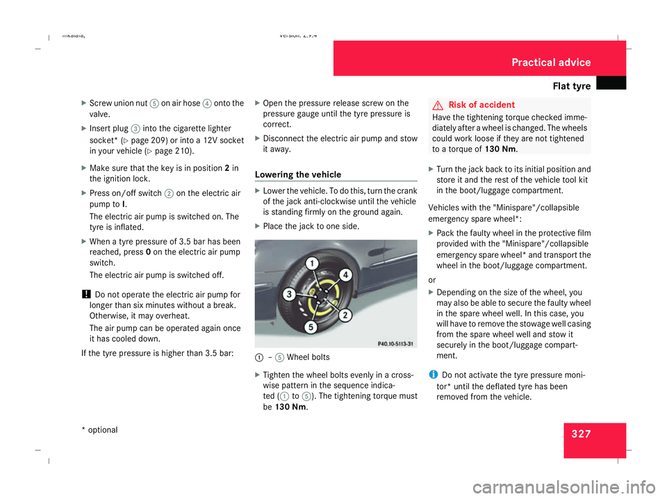
–5 Wheel bolts
X Tighten the wheel bolts evenly in a cross-
wise pattern in the sequence indica-
ted ( 1to5). The tightening torque must
be 130 Nm . G
Risk of accident
Have the tightening torque checked imme-
diately after a wheel is changed. The wheels
could work loose if they are not tightened
to a torque of 130 Nm.
X Turn the jack back to its initial position and
store it and the rest of the vehicle tool kit
in the boot/luggage compartment.
Vehicles with the "Minispare"/collapsible
emergency spare wheel*:
X Pack the faulty wheel in the protective film
provided with the "Minispare"/collapsible
emergency spare wheel* and transport the
wheel in the boot/luggage compartment.
or
X Depending on the size of the wheel, you
may also be able to secure the faulty wheel
in the spare wheel well. In this case, you
will have to remove the stowage well casing
from the spare wheel well and stow it
securely in the boot/luggage compart-
ment.
i Do not activate the tyre pressure moni-
tor* until the deflated tyre has been
removed from the vehicle. Practical advice
* optional
211_AKB; 2; 5, en-GB
mkalafa,
Version: 2.9.4 2008-02-29T16:57:07+01:00 - Seite 327 ZDateiname: 6515_3416_02_buchblock.pdf; preflight