2008 MERCEDES-BENZ E-CLASS ESTATE reset
[x] Cancel search: resetPage 32 of 401
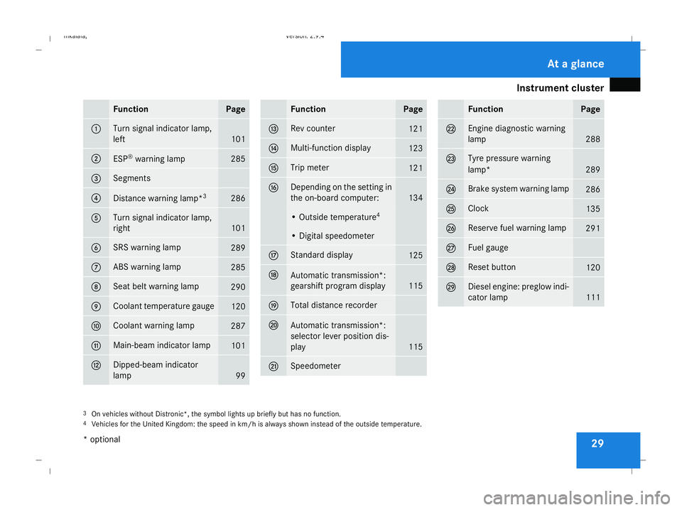
Instrument cluster
29Function Page
1 Turn signal indicator lamp,
left
101
2
ESP
®
warning lamp 285
3 Segments
4
Distance warning lamp*
3 286
5 Turn signal indicator lamp,
right
101
6 SRS warning lamp
289
7 ABS warning lamp
285
8 Seat belt warning lamp
290
9 Coolant temperature gauge
120
a Coolant warning lamp
287
b Main-beam indicator lamp
101
c Dipped-beam indicator
lamp
99 Function Page
d Rev counter
121
e Multi-function display
123
f Trip meter
121
g Depending on the setting in
the on-board computer:
134
• Outside temperature
4 • Digital speedometer
h Standard display
125
j
Automatic transmission*:
gearshift program display
115
k Total distance recorder
l
Automatic transmission*:
selector lever position dis-
play
115
m Speedometer Function Page
n Engine diagnostic warning
lamp
288
o Tyre pressure warning
lamp*
289
p Brake system warning lamp
286
q Clock
135
r Reserve fuel warning lamp
291
s Fuel gauge
t Reset button
120
u Diesel engine: preglow indi-
cator lamp
111
3
On vehicles without Distronic*, the symbol lights up briefly but has no function.
4 Vehicles for the United Kingdom: the speed in km/h is always shown instead of the outside temperature. At a glance
* optional
211_AKB; 2; 5, en-GB
mkalafa,
Version: 2.9.4 2008-02-29T16:57:07+01:00 - Seite 29Dateiname: 6515_3416_02_buchblock.pdf; preflight
Page 50 of 401
Occupant safety
47
If the seat belts are not released:
X
Move the backrest or the seat back slightly
until the belt tension is reduced.
The locking mechanism releases. G
Risk of injury
Make sure when adjusting the seat that
nobody can become trapped.
! Make sure that there are no objects in the
footwell or behind the seats when adjusting
the seats. You could otherwise damage the
seats and the objects. NECK-PRO head restraint
NECK-PRO head restraints are designed to
increase protection to the driver's and front-
passenger's head and neck. To this end, the
head restraints on the driver's and front-
passenger seats are moved forwards and
upwards in the event of a rear-end collision in
the direction of travel. This provides better
head support. G
Risk of injury
Head restraint covers prevent the NECK-
PRO head restraints from triggering cor-
rectly. Consequently, the NECK-PRO head restraints cannot provide the intended level
of protection. Do not use head restraint
covers.
If the NECK-PRO head restraints are triggered
in an accident, you must reset the head
restraints on the driver's and front-passenger
seats (Y page 309). Head restraints that have
been triggered are tilted forwards. Children in the vehicle
If a child is travelling in your vehicle, secure
the child using a child restraint system which
is appropriate to the size and age of the child
and recommended for Mercedes-Benz vehi-
cles. Preferably, you should fit the restraint
system to a suitable rear seat. Ensure that the
child is strapped in throughout the trip.
You can obtain information about the correct
child restraint system from any Mercedes-
Benz Service Centre.
i It is advisable to use Mercedes-Benz care
products to clean child restraint systems.
Information about this can be obtained
from any Mercedes-Benz Service Centre. G
Risk of injury
Do not leave children unsupervised in the
vehicle, even if they are secured in a child
restraint system. Children could injure
themselves on parts of the vehicle. They
could also be seriously or even fatally
injured by prolonged exposure to extreme
heat or cold.
Do not expose the child restraint system to
direct sunlight. The metallic parts of the
child restraint system could heat up and the
child could be burned by them.
If children open a door, they could injure
themselves and others. They could get out
and injure themselves or be injured by a
passing vehicle.
Please also observe the information on
HOLD. Relevant information can be found
in the index. G
Risk of injury
An unsecured or incorrectly positioned load
increases the risk of injury to the child in
the event of:
R an accident
R a braking manoeuvre
R a sudden change of direction Safety
211_AKB; 2; 5, en-GB
mkalafa,
Version: 2.9.4
2008-02-29T16:57:07+01:00 - Seite 47 ZDateiname: 6515_3416_02_buchblock.pdf; preflight
Page 95 of 401
Mirrors
92
X
Make sure that the key is in position 1or
2 in the ignition lock.
X Briefly press button 1.
Both exterior mirrors fold in or out.
i If you are driving faster than 47 km/h, you
can no longer fold in the exterior mirrors.
Make sure that the exterior mirrors are
always folded out fully while the vehicle is
in motion; otherwise, they may vibrate.
Resetting the exterior mirrors If the battery has been disconnected or has
become discharged, the exterior mirrors
must be reset. Otherwise, they will not fold in
when you select the "Fold in mirrors when
locking" function in the on-board computer
(Y page 139).
X Make sure that the key is in position 1in
the ignition lock.
X Briefly press button 1.
Folding the exterior mirrors in or out
automatically* If the "Fold in mirrors when locking" function
is activated in the on-board computer
(Y page 139): R
The exterior mirrors fold in automatically as
soon as you lock the vehicle from the out-
side.
R The exterior mirrors fold out again auto-
matically as soon as you unlock the vehicle
and then open the driver's or front-
passenger door.
i If you have activated this function and fold
in the exterior mirrors using button 1, they
will not be folded out automatically. You
can then only fold out the exterior mirrors
using button 1. Automatic anti-dazzle mirrors*
The rear-view mirror and the exterior mirror
on the driver's side automatically go into anti-
dazzle mode if the ignition is switched on and
incident light from headlamps strikes the sen-
sor in the rear-view mirror.
The mirrors do not go into anti-dazzle mode if
reverse gear is engaged and the interior light-
ing is switched on. G
Risk of accident
If the incident light from headlamps cannot
strike the sensor in the rear-view mirror, for
instance when the rear window blind* is extended, the mirrors' automatic anti-daz-
zle function will not operate.
Incident light could then dazzle you. This
may prevent you from observing the traffic
conditions, thereby causing an accident. In
this case, adjust the rear-view mirror man-
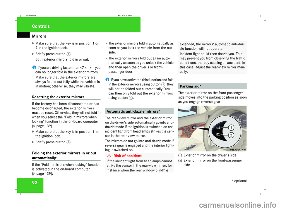
ually. Parking aid*
The exterior mirror on the front-passenger
side moves into the parking position as soon
as you engage reverse gear. 1
Exterior mirror on the driver's side
2 Exterior mirror on the front-passenger
side Controls
* optional
211_AKB; 2; 5, en-GB
mkalafa,
Version: 2.9.4
2008-02-29T16:57:07+01:00 - Seite 92 Dateiname: 6515_3416_02_buchblock.pdf; preflight
Page 96 of 401
Memory functions*
93
X
Make sure that parking position for the
exterior mirror on the front-passenger side
is stored with the memory function
(Y page 94).
X Make sure that the key is in position 2in
the ignition lock.
X Make sure that button 2for the exterior
mirror on the front-passenger side is
pressed in.
X Engage reverse gear.
The exterior mirror on the front-passenger
side moves to the stored parking position.
The exterior mirror on the front-passenger
side moves back to its original position:
R as soon as you exceed a speed of
10 km/h
R about ten seconds after you have disen-
gaged reverse gear
R if you press button 1for the exterior mir-
ror on the driver's side Memory functions*
Storing settings
You can store up to three different settings
using the memory button.
The following settings are stored as a single
memory preset:
R Position of the seat, backrest and head
restraint
R Dynamic driving seat*: activated/deacti-
vated
R Driver's side: steering-wheel position
R Driver's side: position of the exterior mir-
rors on the driver's and front-passenger
sides G
Risk of injury
The memory function can be used when the
key has been removed. For this reason,
children should never be left unsupervised
in the vehicle. They could otherwise
become trapped when moving the seat or
the steering wheel. G
Risk of accident
Only use the memory function on the
driver’s side when the vehicle is stationary.
You could otherwise be distracted from the traffic conditions by the steering wheel and
seat moving of their own accord, and cause
an accident.
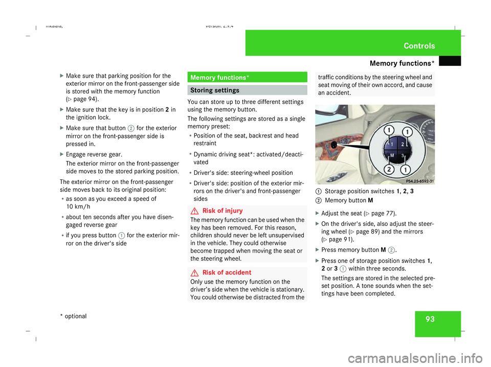
1
Storage position switches 1,2,3
2 Memory button M
X Adjust the seat ( Ypage 77).
X On the driver's side, also adjust the steer-
ing wheel (Y page 89) and the mirrors
(Y page 91).
X Press memory button M2.
X Press one of storage position switches 1,
2 or 31 within three seconds.
The settings are stored in the selected pre-
set position. A tone sounds when the set-
tings have been completed. Controls
* optional
211_AKB; 2; 5, en-GB
mkalafa
, Version: 2.9.4 2008-02-29T16:57:07+01:00 - Seite 93 ZDateiname: 6515_3416_02_buchblock.pdf; preflight
Page 106 of 401
Lights
103Position Load
-1 Front and rear seats occupied
or
Front and rear seats occu-
pied, luggage compartment
laden
0 Front seats occupied
1 Driver's seat occupied, lug-
gage compartment laden
X
Turn thumbwheel for headlamp range 1to
the position which corresponds to the load
in your vehicle. Headlamp cleaning system*
The headlamps are cleaned automatically if
the "Wipe with windscreen washer fluid" func-
tion is operated five times while the lights are
on and the engine is running. When you
switch off the ignition, the automatic head-
lamp cleaning system is reset and counting is
resumed from 0. Intelligent Light System* (vehicles
with bi-xenon headlamps*)
The Intelligent Light System adapts the light-
ing of the front headlamps to the prevailing
driving conditions so that the road is illumi-
nated better.
i The Intelligent Light System is only active
when it is dark.
The Intelligent Light System comprises:
R Active light function
R Cornering light function
R Motorway mode
R Extended range foglamps Active light function For the active light function, the dipped-beam
headlamps swivel horizontally. The swivel
angle changes according to the respective
driving situation. The active light function is
not active when the vehicle is stationary.
Cornering light function
Specially designed headlamps light up the
area into which you are driving when turning
corners.
If you are driving at speeds below 40 km/h,
the cornering light function is activated either
by the turn signals or when the steering wheel
is turned. If you are driving at speeds above
40 km/h the cornering light function is deac-
tivated.
Switching on
X
Make sure that the engine is running.
X Switch on the dipped-beam headlamps.
X Switch off the fog lights.
X Switch on the turn signal.
The cornering light on the same side as the
turn signal comes on, even if you turn the
steering wheel in the opposite direction
after indicating. Controls
* optional
211_AKB; 2; 5, en-GB
mkalafa,
Version: 2.9.4
2008-02-29T16:57:07+01:00 - Seite 103 ZDateiname: 6515_3416_02_buchblock.pdf; preflight
Page 111 of 401
Side windows
108
i
You can disable the controls for the rear
side windows from the driver's seat
(Y page 47).
i If PRE-SAFE ®
has been activated, the side
windows close automatically, leaving a
small gap.
The switches for all side windows are located
on the driver's door. There is also a switch on
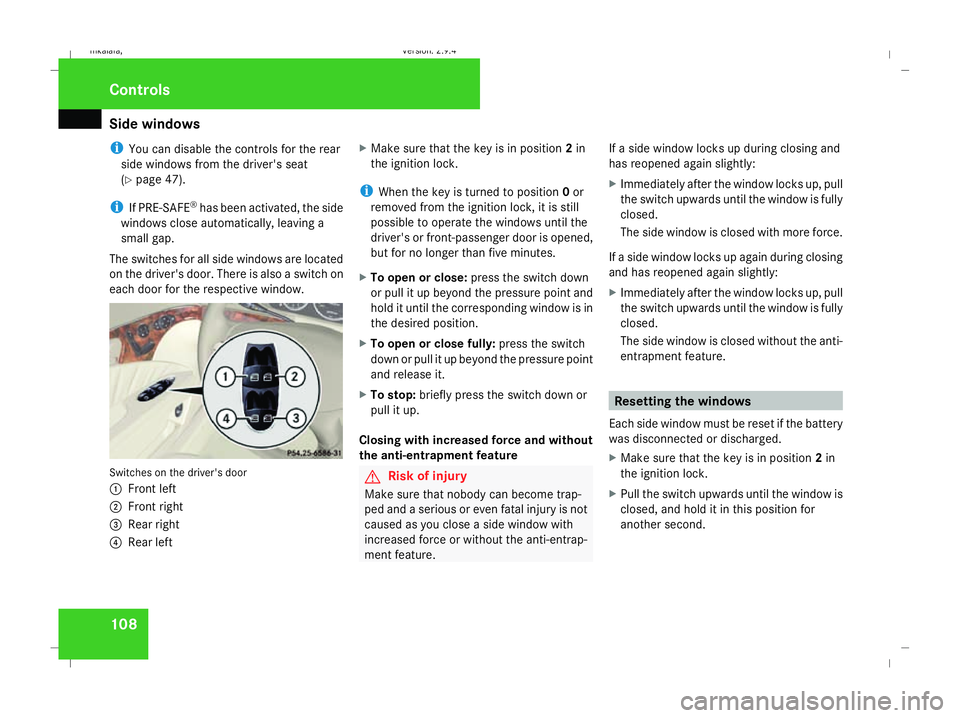
each door for the respective window. Switches on the driver's door
1
Front left
2 Front right
3 Rear right
4 Rear left X
Make sure that the key is in position 2in
the ignition lock.
i When the key is turned to position 0or
removed from the ignition lock, it is still
possible to operate the windows until the
driver's or front-passenger door is opened,
but for no longer than five minutes.
X To open or close: press the switch down
or pull it up beyond the pressure point and
hold it until the corresponding window is in
the desired position.
X To open or close fully: press the switch
down or pull it up beyond the pressure point
and release it.
X To stop: briefly press the switch down or
pull it up.
Closing with increased force and without
the anti-entrapment feature G
Risk of injury
Make sure that nobody can become trap-
ped and a serious or even fatal injury is not
caused as you close a side window with
increased force or without the anti-entrap-
ment feature. If a side window locks up during closing and
has reopened again slightly:
X
Immediately after the window locks up, pull
the switch upwards until the window is fully
closed.
The side window is closed with more force.
If a side window locks up again during closing
and has reopened again slightly:
X Immediately after the window locks up, pull
the switch upwards until the window is fully
closed.
The side window is closed without the anti-
entrapment feature. Resetting the windows
Each side window must be reset if the battery
was disconnected or discharged.
X Make sure that the key is in position 2in
the ignition lock.
X Pull the switch upwards until the window is
closed, and hold it in this position for
another second. Controls
211_AKB; 2; 5, en-GB
mkalafa,
Version: 2.9.4 2008-02-29T16:57:07+01:00 - Seite 108Dateiname: 6515_3416_02_buchblock.pdf; preflight
Page 123 of 401
Instrument cluster
120 Instrument cluster
Points to remember
You will find a full overview of the instrument
cluster in the "At a glance" section
(Y page 26). G
Risk of accident
No further messages can be displayed if the
instrument cluster and/or the multi-func-
tion display fails.
This means that you will not see information
about the driving situation, such as the
speed, outside temperature, warning/indi-
cator lamps, display messages or system
failures. The vehicle's handling character-
istics may be affected. Adjust your driving
style and speed accordingly.
Immediately consult a qualified specialist
workshop which has the necessary special-
ist knowledge and tools to carry out the
work required. Mercedes-Benz recom-
mends that you use a Mercedes-Benz
Service Centre for this purpose. In particu-
lar, work relevant to safety or on safety-
related systems must be carried out at a
qualified specialist workshop. Activating the multi-function display
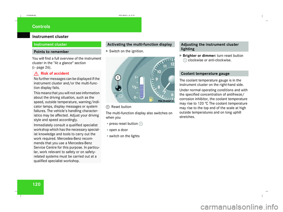
X Switch on the ignition. 1
Reset button
The multi-function display also switches on
when you
R press reset button 1
R open a door
R switch on the lights Adjusting the instrument cluster
lighting
X Brighter or dimmer: turn reset button
1 clockwise or anti-clockwise. Coolant temperature gauge
The coolant temperature gauge is in the
instrument cluster on the right-hand side.
Under normal operating conditions and with
the specified concentration of antifreeze/
corrosion inhibitor, the coolant temperature
may rise to 120 † The coolant temperature
may rise to the top end of the scale at high
outside temperatures and on long uphill
stretches. Controls
211_AKB; 2; 5, en-GB
mkalafa
, Version: 2.9.4 2008-02-29T16:57:07+01:00 - Seite 120Dateiname: 6515_3416_02_buchblock.pdf; preflight
Page 124 of 401
On-board computer
121Resetting the trip meter
X Select the standard display menu
(Y page 125).
X Press and hold reset button 1until the trip
meter is reset. Speedometer with segments
The segments in the speedometer indicate
which speed range is available.
Cruise control mode:
The segments light up from the stored speed
to the maximum speed.
Distronic* mode:
One or two segments around the stored
speed light up.
Variable Speedtronic mode:
The segments light up from the start of the
scale to the selected limit speed. Rev counter
The red band in the rev counter indicates the
engine's overrevving range. The fuel supply is
interrupted to protect the engine when the
red band is reached.
! Do not drive in the overrevving range.
Doing so will damage the engine. H
Environmental note
Avoid driving at high engine speeds, as this
increases your vehicle's consumption
unnecessarily and pollutes the environ-
ment through increased emissions. Outside temperature display
G
Risk of accident
The road surface may be icy, especially in
wooded areas or on bridges, even if tem-
peratures are just above freezing point. The
vehicle could skid if you fail to adapt your
driving style. You should therefore always
adapt your driving style and speed to suit
the weather conditions.
There is a short delay before a change in out-
side temperature is displayed. On-board computer
Points to remember
The on-board computer is activated as soon
as the key is turned to position 1in the igni-
tion lock. You can use the on-board computer
to call up information relating to your vehicle
and to make and adjust settings.
You can call up the next service due date,
select the display language for the instrument
cluster and set other functions. G
Risk of accident
Only use the on-board computer when road
and traffic conditions permit. You would
otherwise be distracted and unable to con-
centrate properly on driving, and could
cause an accident.
The on-board computer shows information in
the multi-function display. Controls
* optional
211_AKB; 2; 5, en-GB
mkalafa,
Version: 2.9.4
2008-02-29T16:57:07+01:00 - Seite 121 ZDateiname: 6515_3416_02_buchblock.pdf; preflight