2008 MERCEDES-BENZ E-CLASS ESTATE tow bar
[x] Cancel search: tow barPage 12 of 401
9
Checking the battery . . . . . . . . . .
.310
Convenience closing . . . . . . . . . . .110
Display message . . . . . . . . . . . . . .279
Factory setting . . . . . . . . . . . . . .66, 67
Loss . . . . . . . . . . . . . . . . . . . . . . . .301
Malfunction . . . . . . . . . . . . . . . . . .301
Modifying the programming . . . . . . .66
KEYLESS GO . . . . . . . . . . . . . . . . . . . . .67
Button . . . . . . . . . . . . . . . . . . . . . . .77
Changing the battery . . . . . . . . . . .310
Checking the battery . . . . . . . . . . .310
Closing the boot lid automatically . .74
Convenience closin g.. . . . . . . . ..110
Factory settings . . . . . . . . . . . . . . . .68
Losing the key . . . . . . . . . . . . . . . .304
Malfunction . . . . . . . . . . . . . . . . . .303
Modifying the programming . . . . . . .68
Starting the engine . . . . . . . . . . . .111
Key positions
Key . . . . . . . . . . . . . . . . . . . . . . . . . .76
KEYLESS GO . . . . . . . . . . . . . . . . . .77
Kickdown . . . . . . . . . . . . . . . . . .117, 119 L
Lamp Display message . . . . . . . . . . . . . .272
Lamps
see Indicator and warning lamp
Language
Selecting (on-board computer) . . .133 Lashing eyelets
. . . . . . . . . . . . . . . . .191
Licence plate lighting Display message . . . . . . . . . . . . . .275
Lighting
see Lights
Lights
Active light function . . . . . . . . . . . .103
Automatic headlamp mode . . . . . .100
Constant headlamp mode . . . . . . . .99
Cornering light function . . . . . . . . .103
Dipped-beam headlamps . . . . . . . . .99
Display message . . . . . . . . . . . . . .272
Fog lights . . . . . . . . . . . . . . . .100, 104
Hazard warning lamps . . . . . . . . . .102
Headlamp flasher . . . . . . . . . . . . . .101
Headlamp range . . . . . . . . . . . . . . .102
Light switch . . . . . . . . . . . . . . . . . . .99
Main-beam headlamps . . . . . . . . . .101
Motorway mode . . . . . . . . . . . . . . .104
Rear foglamp . . . . . . . . . . . . . . . . .100
Switching off (display message) . . .275
Turn signals . . . . . . . . . . . . . . . . . .101
LIM indicator lamp
Cruise control . . . . . . . . . . . . . . . .143
Distronic . . . . . . . . . . . . . . . . . . . .146
Variable Speedtronic . . . . . . . . . . .152
Load compartment load, maximum
. . . . . . . . . . . . . .370, 371, 372, 373, 374
Loading guidelines . . . . . . . . . . . . ..190 Locking
Automatic . . . . . . . . . . . . . . . . . . . . .70
Emergency locking . . . . . . . . . . . . .307
From the inside (central locking
button) . . . . . . . . . . . . . . . . . . . . . . .70
Luggage compartment enlarge-
ment . . . . . . . . . . . . . . . . . . . . . . . . . .198
Luggage compartment floor extending . . . . . . . . . . . . . . . . . . . .194
opening/closing . . . . . . . . . .193, 195
removing . . . . . . . . . . . . . . . . . . . .194
stowage well, unde r.. . . . . . . . . . .192
Luggage cover . . . . . . . . . . . . . . . . . .201
Luggage net Front-passenger footwell . . . . . . . .190
Luggage well
Removing/fitting . . . . . . . . . . . . . .256
Lumbar support
see Lumbar support
Luxury head restraint . . . . . . . . ..79, 81 M
Main-beam headlamps Display message . . . . . . . . . . . . . .274
Main fuse box . . . . . . . . . . . . . . . . . . .341
Maintenance Battery . . . . . . . . . . . . . . . . . . . . . .329
Malfunction memory
see Message memory menu Index
211_AKB; 2; 5, en-GB
mkalafa,
Version: 2.9.4
2008-02-29T16:57:07+01:00 - Seite 9 Dateiname: 6515_3416_02_buchblock.pdf; preflight
Page 84 of 401
Seats
81
Luxury head restraint* G
Risk of injury
When folding back the head restraint side
bolsters, do not put your hands between
the side bolster and the cushion holder.
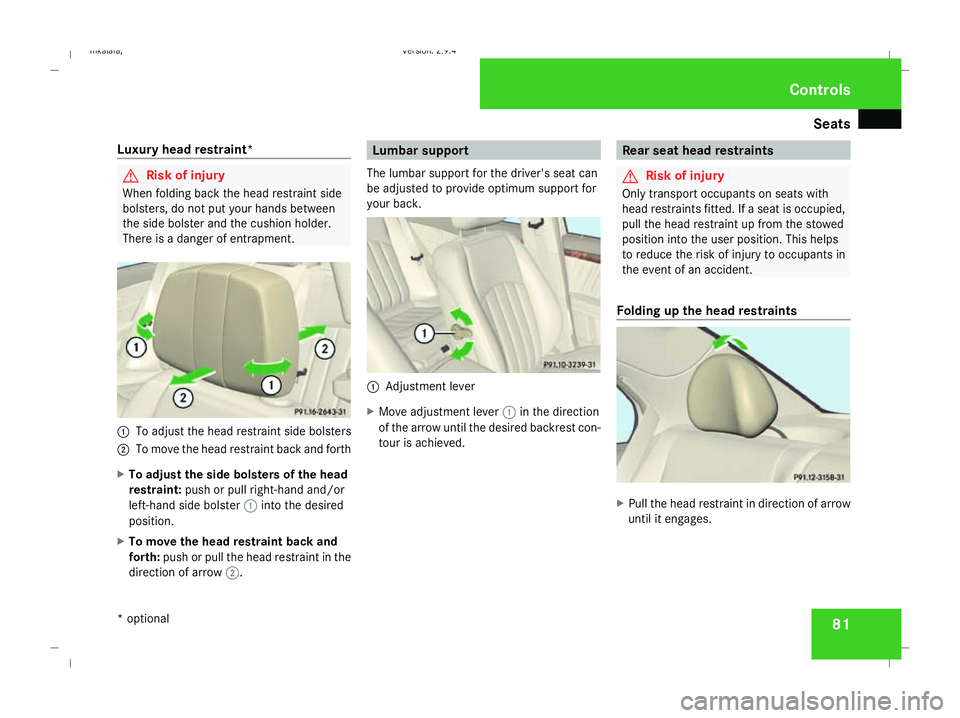
There is a danger of entrapment. 1
To adjust the head restraint side bolsters
2 To move the head restraint back and forth
X To adjust the side bolsters of the head
restraint: push or pull right-hand and/or
left-hand side bolster 1into the desired
position.
X To move the head restraint back and
forth: push or pull the head restraint in the
direction of arrow 2. Lumbar support
The lumbar support for the driver's seat can
be adjusted to provide optimum support for
your back. 1
Adjustment lever
X Move adjustment lever 1in the direction
of the arrow until the desired backrest con-
tour is achieved. Rear seat head restraints
G
Risk of injury
Only transport occupants on seats with
head restraints fitted. If a seat is occupied,
pull the head restraint up from the stowed
position into the user position. This helps
to reduce the risk of injury to occupants in
the event of an accident.
Folding up the head restraints X
Pull the head restraint in direction of arrow
until it engages. Controls
* optional
211_AKB; 2; 5, en-GB
mkalafa,
Version: 2.9.4 2008-02-29T16:57:07+01:00 - Seite 81 ZDateiname: 6515_3416_02_buchblock.pdf; preflight
Page 162 of 401
Driving sys
tems 1591
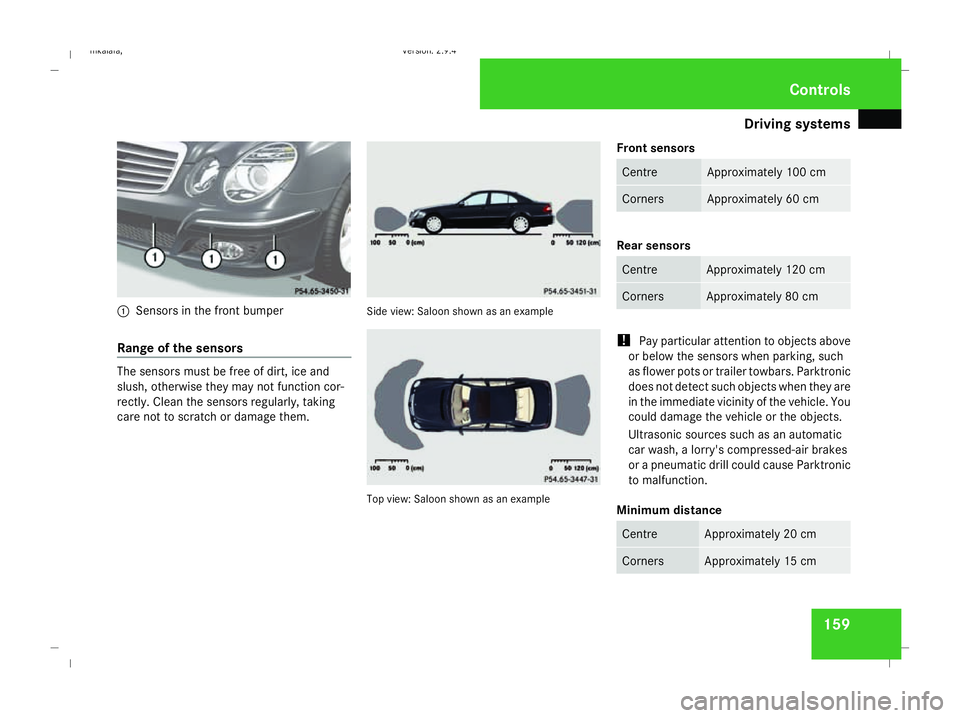
Sensors in the front bumper
Range of the sensors The sensors must be free of dirt, ice and
slush, otherwise they may not function cor-
rectly. Clean the sensors regularly, taking
care not to scratch or damage them. Side view: Saloon shown as an example
Top view: Saloon shown as an exampleFront sensors Centre Approximately 100 cm
Corners Approximately 60 cm
Rear sensors
Centre Approximately 120 cm
Corners Approximately 80 cm
!
Pay particular attention to objects above
or below the sensors when parking, such
as flower pots or trailer towbars. Parktronic
does not detect such objects when they are
in the immediate vicinity of the vehicle. You
could damage the vehicle or the objects.
Ultrasonic sources such as an automatic
car wash, a lorry's compressed-air brakes
or a pneumatic drill could cause Parktronic
to malfunction.
Minimum distance Centre Approximately 20 cm
Corners Approximately 15 cm Controls
211_AKB; 2; 5, en-GB
mkalafa
, Version: 2.9.4 2008-02-29T16:57:07+01:00 - Seite 159 ZDateiname: 6515_3416_02_buchblock.pdf; preflight
Page 243 of 401
Trailer towing
240
X
Press the ball coupling in the direction of
the arrow by hand until it engages in a ver-
tical position.
Indicator lamp 2goes out.
The message Trailer tow hitch
Check locking mech. is shown in the
multi-function display until the ball cou-
pling is engaged.
X Remove the protective cap from the ball
coupling. Notes on towing a trailer
G
Risk of accident
When reversing the vehicle towards the
trailer, make sure there is nobody between
the trailer and the vehicle.
Couple and uncouple the trailer carefully. If
you do not couple the trailer to the towing
vehicle correctly, the trailer could become
detached.
Make sure that the following values are not
exceeded:
R The permitted trailer drawbar nose-
weight
R The permitted trailer load R
The permitted rear axle load of the towing
vehicle
R The maximum permissible gross vehicle
weight of both the towing vehicle and the
trailer
You will find the applicable permissible val-
ues which must not be exceeded in the
vehicle documents.
You will find the values approved by the
manufacturer on the vehicle identification
plates and those for the towing vehicle in
the “Technical data” section.
You will find installation dimensions and loads
in the "Technical data" section
(Y page 375).
The maximum permissible trailer drawbar
noseweight on the ball coupling is 76 kg
(Saloon) or 84 kg (Estate). However, the
actual noseweight must not exceed the value
given on the trailer coupling and trailer iden-
tification plates. The lowest weight applies.
! Use a noseweight as close as possible to
the maximum permissible noseweight. Do
not use a noseweight of less than 50 kg,
otherwise the trailer may come loose. Bear in mind that the payload and the rear
axle load are reduced by the actual nose-
weight.
i On vehicles without level control, the
height of the ball coupling will alter accord-
ing to the load placed on the vehicle. In this
case, you should use a trailer with a height-
adjustable drawbar.
Coupling up a trailer G
Risk of injury
Do not connect a trailer with an engaged
overrun brake. Otherwise, your hand could
become trapped between the bumper and
drawbar.
! Do not uncouple a trailer with overrun
brake between the bumper and drawbar,
otherwise your vehicle could be damaged
by the spring action of the overrun brake.
X Position the trailer level behind the vehicle.
X Couple up the trailer.
X Establish the electrical connection
between the vehicle and the trailer. Operation
211_AKB; 2; 5, en-GB
mkalafa
,V ersion: 2.9.4
2008-02-29T16:57:07+01:00 - Seite 240 Dateiname: 6515_3416_02_buchblock.pdf; preflight
Page 323 of 401
Flat tyre
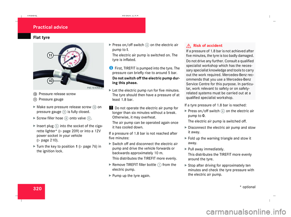
320a
Pressure release screw
b Pressure gauge
X Make sure pressure release screw aon
pressure gauge bis fully closed.
X Screw filler hose 8onto valve 9.
X Insert plug 5into the socket of the ciga-
rette lighter* (Y page 209) or into a 12V
power socket in your vehicle
(Y page 210).
X Turn the key to position 1(Y page 76) in
the ignition lock. X
Press on/off switch 4on the electric air
pump to I.
The electric air pump is switched on. The
tyre is inflated.
i First, TIREFIT is pumped into the tyre. The
pressure can briefly rise to around 5 bar.
Do not switch off the electric pump dur-
ing this phase.
X Let the electric pump run for five minutes.
The tyre should then have a pressure of at
least 1.8 bar.
! Do not operate the electric air pump for
longer than six minutes without a break.
Otherwise, it may overheat.
The air pump can be operated again once
it has cooled down.
If a pressure of 1.8 bar is not reached after
five minutes:
X Switch off and disconnect the electric air
pump and drive the vehicle forwards or
backwards approximately 10 m.
This distributes the TIREFIT more evenly.
X Remove TIREFIT filler bottle 1from the
electric pump.
X Pump up the tyre again. G
Risk of accident
If a pressure of 1.8 bar is not achieved after
five minutes, the tyre is too badly damaged.
Do not drive any further. Consult a qualified
specialist workshop which has the neces-
sary specialist knowledge and tools to carry
out the work required. Mercedes-Benz rec-
ommends that you use a Mercedes-Benz
Service Centre for this purpose. In particu-
lar, work relevant to safety or on safety-
related systems must be carried out at a
qualified specialist workshop.
If a tyre pressure of 1.8 bar is reached:
X Press on/off switch 4on the electric air
pump to 0.
The electric air pump is switched off.
X Disconnect the electric air pump and stow
it away.
X Fold up the warning triangle and stow it
away.
X Pull away immediately.
This distributes the TIREFIT more evenly
around the tyre.
X Stop after driving for approximately ten
minutes and check the tyre pressure with
the electric air pump. Practical advice
* optional
211_AKB; 2; 5, en-GB
mkalafa,
Version: 2.9.4 2008-02-29T16:57:07+01:00 - Seite 320Dateiname: 6515_3416_02_buchblock.pdf; preflight
Page 325 of 401
Flat tyre
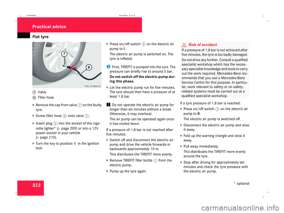
3227
Valve
8 Filler hose
X Remove the cap from valve 7on the faulty
tyre.
X Screw filler hose 8onto valve 7.
X Insert plug 4into the socket of the ciga-
rette lighter* (Y page 209) or into a 12V
power socket in your vehicle
(Y page 210).
X Turn the key to position 1in the ignition
lock. X
Press on/off switch 3on the electric air
pump to I.
The electric air pump is switched on. The
tyre is inflated.
i First, TIREFIT is pumped into the tyre. The
pressure can briefly rise to around 5 bar.
Do not switch off the electric pump dur-
ing this phase.
X Let the electric pump run for five minutes.
The tyre should then have a pressure of at
least 1.8 bar.
! Do not operate the electric air pump for
longer than six minutes without a break.
Otherwise, it may overheat.
The air pump can be operated again once
it has cooled down.
If a pressure of 1.8 bar is not reached after
five minutes:
X Switch off and disconnect the electric air
pump and drive the vehicle forwards or
backwards approximately 10 m.
This distributes the TIREFIT more evenly.
X Remove TIREFIT filler bottle 1from the
electric pump.
X Pump up the tyre again. G
Risk of accident
If a pressure of 1.8 bar is not achieved after
five minutes, the tyre is too badly damaged.
Do not drive any further. Consult a qualified
specialist workshop which has the neces-
sary specialist knowledge and tools to carry
out the work required. Mercedes-Benz rec-
ommends that you use a Mercedes-Benz
Service Centre for this purpose. In particu-
lar, work relevant to safety or on safety-
related systems must be carried out at a
qualified specialist workshop.
If a tyre pressure of 1.8 bar is reached:
X Press on/off switch 3on the electric air
pump to 0.
The electric air pump is switched off.
X Disconnect the electric air pump and stow
it away.
X Fold up the warning triangle and stow it
away.
X Pull away immediately.
This distributes the TIREFIT more evenly
around the tyre.
X Stop after driving for approximately ten
minutes and check the tyre pressure with
the electric air pump. Practical advice
* optional
211_AKB; 2; 5, en-GB
mkalafa,
Version: 2.9.4 2008-02-29T16:57:07+01:00 - Seite 322Dateiname: 6515_3416_02_buchblock.pdf; preflight
Page 330 of 401
Flat tyre
327
X
Screw union nut 5on air hose 4onto the
valve.
X Insert plug 3into the cigarette lighter
socket* ( Ypage 209) or into a 12V socket
in your vehicle (Y page 210).
X Make sure that the key is in position 2in
the ignition lock.
X Press on/off switch 2on the electric air
pump to I.
The electric air pump is switched on. The
tyre is inflated.
X When a tyre pressure of 3.5 bar has been
reached, press 0on the electric air pump
switch.
The electric air pump is switched off.
! Do not operate the electric air pump for
longer than six minutes without a break.
Otherwise, it may overheat.
The air pump can be operated again once
it has cooled down.
If the tyre pressure is higher than 3.5 bar: X
Open the pressure release screw on the
pressure gauge until the tyre pressure is
correct.
X Disconnect the electric air pump and stow
it away.
Lowering the vehicle X
Lower the vehicle. To do this, turn the crank
of the jack anti-clockwise until the vehicle
is standing firmly on the ground again.
X Place the jack to one side. 1
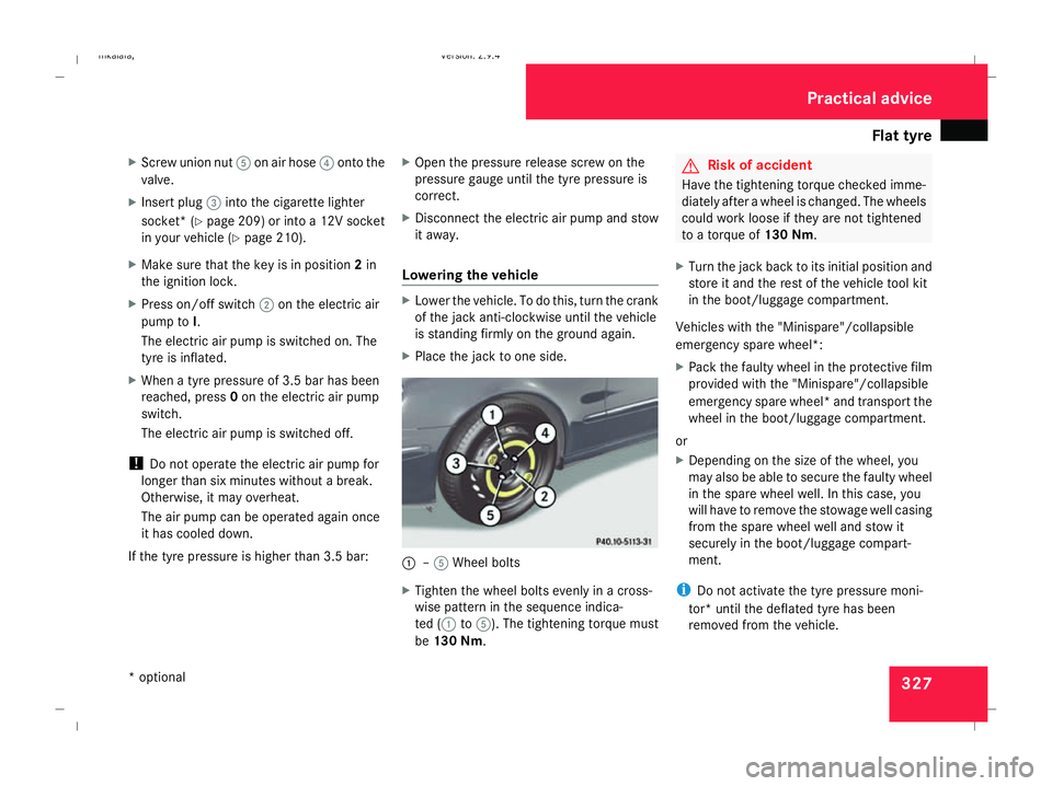
–5 Wheel bolts
X Tighten the wheel bolts evenly in a cross-
wise pattern in the sequence indica-
ted ( 1to5). The tightening torque must
be 130 Nm . G
Risk of accident
Have the tightening torque checked imme-
diately after a wheel is changed. The wheels
could work loose if they are not tightened
to a torque of 130 Nm.
X Turn the jack back to its initial position and
store it and the rest of the vehicle tool kit
in the boot/luggage compartment.
Vehicles with the "Minispare"/collapsible
emergency spare wheel*:
X Pack the faulty wheel in the protective film
provided with the "Minispare"/collapsible
emergency spare wheel* and transport the
wheel in the boot/luggage compartment.
or
X Depending on the size of the wheel, you
may also be able to secure the faulty wheel
in the spare wheel well. In this case, you
will have to remove the stowage well casing
from the spare wheel well and stow it
securely in the boot/luggage compart-
ment.
i Do not activate the tyre pressure moni-
tor* until the deflated tyre has been
removed from the vehicle. Practical advice
* optional
211_AKB; 2; 5, en-GB
mkalafa,
Version: 2.9.4 2008-02-29T16:57:07+01:00 - Seite 327 ZDateiname: 6515_3416_02_buchblock.pdf; preflight
Page 340 of 401
Towing and tow-starting
337Towing and tow-starting
Points to remember
G
Risk of accident
If you tow the vehicle, you must use a rigid
towing bar if:
R the engine is not running
R there is a brake system malfunction
R the voltage supply or the vehicle's elec-
trical system is damaged
The electric power steering and the brake
force boosting effect do not work when the
engine is not running. Greater braking force
will then be required and the brake pedal
travel will be longer. If necessary, depress
the brake pedal with maximum force.
Do not tow the vehicle if the key cannot be
turned in the ignition lock. If this is the case,
the steering is locked and the vehicle can-
not be steered.
If you tow or tow-start another vehicle, its
weight must not exceed the maximum per-
missible gross vehicle weight of your vehi-
cle. G
Risk of accident
The vehicle is braked when HOLD is activa-
ted. Therefore, deactivate HOLD if the vehi-
cle is to be towed.
If you tow or tow-start another vehicle, its
weight must not exceed the maximum per-
missible gross vehicle weight of your vehi-
cle.
It is better to have the vehicle transported
than to have it towed.
When towing, observe the legal requirements
in all countries concerned.
! When towing, pull away slowly and with-
out jerking. If the tractive power is too high,
the vehicles could be damaged. Do not use
the towing eye for recovery.
! You may tow the vehicle for a maximum
of 50 km. A towing speed of 50 km/h must
not be exceeded.
With towing distances over 50 km, the
entire vehicle needs to be lifted up and
transported.
! Only secure the tow cable or towing bar
to the towing eyes. You may otherwise
damage the vehicle. R
Vehicles with an automatic transmission*
must not be tow-started.
R If the engine does not start, try jump start-
ing (Y page 333).
R If it is not possible to jump-start the vehicle,
have it towed to the nearest qualified spe-
cialist workshop, e.g. a Mercedes-Benz
Service Centre.
R If the vehicle has suffered transmission
damage, only tow it with the propeller shaft
disconnected.
R The automatic transmission* selector lever
must be in the Nposition when towing the
vehicle away.
R If you are towing the vehicle over a consid-
erable distance, this must only be done
with the rear axle raised.
R The ignition must be switched off if you are
towing the vehicle with the front/rear axle
raised. Intervention by ESP ®
could other-
wise damage the brake system.
R Vehicles with 4MATIC* may not be towed
with the front or rear axle raised.
R Before towing the vehicle, make sure that
the battery is connected and charged. Oth-
erwise: Practical advice
* optional
211_AKB; 2; 5, en-GB
mkalafa
,V ersion: 2.9.4
2008-02-29T16:57:07+01:00 - Seite 337 ZDateiname: 6515_3416_02_buchblock.pdf; preflight