2008 MERCEDES-BENZ E-CLASS ESTATE set clock
[x] Cancel search: set clockPage 30 of 401
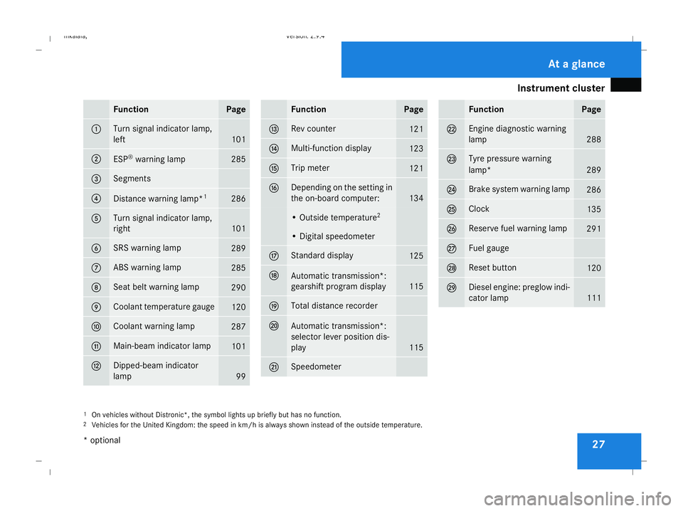
Instrument cluster
27Function Page
1 Turn signal indicator lamp,
left
101
2
ESP
®
warning lamp 285
3 Segments
4
Distance warning lamp*
1 286
5 Turn signal indicator lamp,
right
101
6 SRS warning lamp
289
7 ABS warning lamp
285
8 Seat belt warning lamp
290
9 Coolant temperature gauge
120
a Coolant warning lamp
287
b Main-beam indicator lamp
101
c Dipped-beam indicator
lamp
99 Function Page
d Rev counter
121
e Multi-function display
123
f Trip meter
121
g Depending on the setting in
the on-board computer:
134
• Outside temperature
2 • Digital speedometer
h Standard display
125
j
Automatic transmission*:
gearshift program display
115
k Total distance recorder
l
Automatic transmission*:
selector lever position dis-
play
115
m Speedometer Function Page
n Engine diagnostic warning
lamp
288
o Tyre pressure warning
lamp*
289
p Brake system warning lamp
286
q Clock
135
r Reserve fuel warning lamp
291
s Fuel gauge
t Reset button
120
u Diesel engine: preglow indi-
cator lamp
111
1
On vehicles without Distronic*, the symbol lights up briefly but has no function.
2 Vehicles for the United Kingdom: the speed in km/h is always shown instead of the outside temperature. At a glance
* optional
211_AKB; 2; 5, en-GB
mkalafa,
Version: 2.9.4 2008-02-29T16:57:07+01:00 - Seite 27Dateiname: 6515_3416_02_buchblock.pdf; preflight
Page 32 of 401
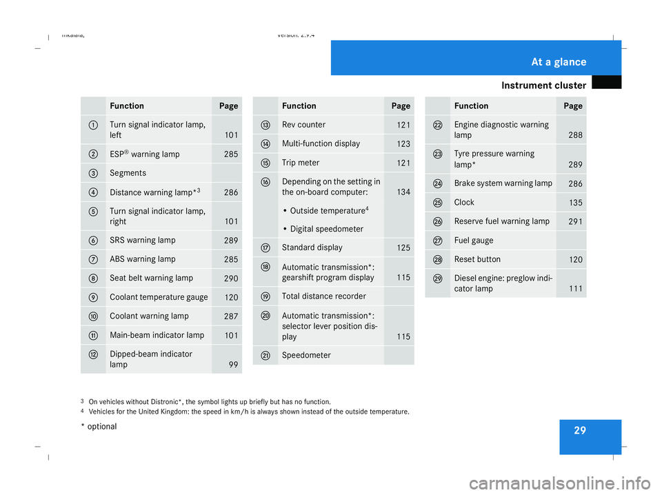
Instrument cluster
29Function Page
1 Turn signal indicator lamp,
left
101
2
ESP
®
warning lamp 285
3 Segments
4
Distance warning lamp*
3 286
5 Turn signal indicator lamp,
right
101
6 SRS warning lamp
289
7 ABS warning lamp
285
8 Seat belt warning lamp
290
9 Coolant temperature gauge
120
a Coolant warning lamp
287
b Main-beam indicator lamp
101
c Dipped-beam indicator
lamp
99 Function Page
d Rev counter
121
e Multi-function display
123
f Trip meter
121
g Depending on the setting in
the on-board computer:
134
• Outside temperature
4 • Digital speedometer
h Standard display
125
j
Automatic transmission*:
gearshift program display
115
k Total distance recorder
l
Automatic transmission*:
selector lever position dis-
play
115
m Speedometer Function Page
n Engine diagnostic warning
lamp
288
o Tyre pressure warning
lamp*
289
p Brake system warning lamp
286
q Clock
135
r Reserve fuel warning lamp
291
s Fuel gauge
t Reset button
120
u Diesel engine: preglow indi-
cator lamp
111
3
On vehicles without Distronic*, the symbol lights up briefly but has no function.
4 Vehicles for the United Kingdom: the speed in km/h is always shown instead of the outside temperature. At a glance
* optional
211_AKB; 2; 5, en-GB
mkalafa,
Version: 2.9.4 2008-02-29T16:57:07+01:00 - Seite 29Dateiname: 6515_3416_02_buchblock.pdf; preflight
Page 123 of 401
Instrument cluster
120 Instrument cluster
Points to remember
You will find a full overview of the instrument
cluster in the "At a glance" section
(Y page 26). G
Risk of accident
No further messages can be displayed if the
instrument cluster and/or the multi-func-
tion display fails.
This means that you will not see information
about the driving situation, such as the
speed, outside temperature, warning/indi-
cator lamps, display messages or system
failures. The vehicle's handling character-
istics may be affected. Adjust your driving
style and speed accordingly.
Immediately consult a qualified specialist
workshop which has the necessary special-
ist knowledge and tools to carry out the
work required. Mercedes-Benz recom-
mends that you use a Mercedes-Benz
Service Centre for this purpose. In particu-
lar, work relevant to safety or on safety-
related systems must be carried out at a
qualified specialist workshop. Activating the multi-function display
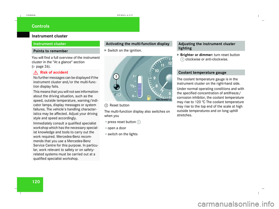
X Switch on the ignition. 1
Reset button
The multi-function display also switches on
when you
R press reset button 1
R open a door
R switch on the lights Adjusting the instrument cluster
lighting
X Brighter or dimmer: turn reset button
1 clockwise or anti-clockwise. Coolant temperature gauge
The coolant temperature gauge is in the
instrument cluster on the right-hand side.
Under normal operating conditions and with
the specified concentration of antifreeze/
corrosion inhibitor, the coolant temperature
may rise to 120 † The coolant temperature
may rise to the top end of the scale at high
outside temperatures and on long uphill
stretches. Controls
211_AKB; 2; 5, en-GB
mkalafa
, Version: 2.9.4 2008-02-29T16:57:07+01:00 - Seite 120Dateiname: 6515_3416_02_buchblock.pdf; preflight
Page 138 of 401
On-board computer
135
X
Press the èor· button to select the
Settings... menu.
X Press the jbutton to call up the selec-
tion of submenus.
X Press the æorç button to select the
Time/Date submenu.
Setting the time
X Use the jbutton to select Clock,
hours Press R to confirm (orClock,
minutes Press R to confirm ).
X Press the æorç button to set a
value.
X Press the reset button on the left of the
instrument cluster.
The set time is stored.
Setting the date
X Press the jbutton to select Set date
Day (orSet date Month orSet date
Year).
X Press the æorç button to set the
values.
X Press the j,èorÿ button to
select a different display. Setting constant headlamp mode If you have set constant headlamp mode and
the light switch is in position MorU,
the side lamps, dipped-beam headlamps and
licence plate lighting are switched on auto-
matically when the engine is running. Turning
the light switch to a different position
switches on the corresponding lights. Make
sure that the light switch is turned to Bor
U if you switch off constant headlamp
mode while driving in the dark.
In countries in which constant headlamp
mode is a legal requirement, Constantis the
factory setting.
X Press the èor· button to select the
Settings... menu.
X Press the jbutton to call up the selec-
tion of submenus.
X Press the æorç button to select the
Lighting submenu.
X Press the jbutton to select Headlamp
mode. X
Press the æorç button to set the
mode for the headlamps to ManualorCon-
stant (constant headlamp mode).
X Press the j,èorÿ button to
select a different display.
Switching the surround lighting on or
off If the surround lighting is switched on, the
following lights will be switched on automat-
ically in the dark after you have unlocked the
vehicle using the key:
R
the side lamps
R the tail lamps
R the licence plate lighting
R the front foglamps
The surround lighting switches off automati-
cally if you open the driver's door or after 40
seconds.
X Press èor· to select the Set-
tings... menu.
X Press the jbutton to call up the selec-
tion of submenus.
X Press the æorç button to select the
Lighting submenu. Controls
211_AKB; 2; 5, en-GB
mkalafa,
Version: 2.9.4
2008-02-29T16:57:07+01:00 - Seite 135 ZDateiname: 6515_3416_02_buchblock.pdf; preflight
Page 174 of 401
Air conditioning
171
4-zone Thermotronic*: the temperature for
each of the four air-conditioning zones can be
set individually. You can set the temperature
separately for the driver's and front-
passenger sides as well as for the left and
right sides of the rear compartment.
Setting the temperature in the front
compartment using 2-zone Thermatic X
Make sure that the key is in position 2in
the ignition lock.
X To increase/reduce: turn thumbwheels
1 and 7clockwise or anti-clockwise
(Y page 164). Only change the temperature
setting in small increments. Start at 22 †.
Setting the temperature in the front
compartment via 4-zone
Thermotronic* X
Make sure that the key is in position 2in
the ignition lock.
X To increase/reduce: press the$or
% button. Only change the temperature
setting in small increments. Start at 22 †.
The set temperature is shown in the 4-zone
Thermotronic* display. Setting the temperature in the rear
compartment via 4-zone
Thermotronic* X
Make sure that the key is in position 2in
the ignition lock.
X Press the ™button.
The 4-zone Thermotronic* display switches
to the rear-compartment air-conditioning
settings.
X To increase/reduce: press the$or
% button. Only change the temperature
setting in small increments. Start at 22 †.
The set temperature is shown in the 4-zone
Thermotronic* display. The 4-zone
Thermotronic* display changes back to the
standard display about five seconds after a
button is pressed.
i You can also return to the standard dis-
play by pressing the ™button again. Setting the rear-compartment temper-
ature via the rear-compartment air con-
ditioning* X
Make sure that the key is in position 2in
the ignition lock.
X To increase/reduce: press the$or
% button. Only change the temperature
setting in small increments. Start at 22 †. Adjusting the air vents
G
Risk of injury
Very hot or very cold air can flow from the
air vents. This could cause burns or frost-
bite to bare skin in the immediate vicinity
of the vents. Keep bare skin away from
these air outlets. If necessary, direct the
airflow away to a different area of the vehi-
cle interior.
Please observe the following notes to ensure
that the air can flow freely through the air
vents:
R Keep the air inlet between the windscreen
and the bonnet free of deposits, such as ice Cont
rols
* optional
211_AKB; 2; 5, en-GB
mkalafa ,V ersion: 2.9.4
2008-02-29T16:57:07+01:00 - Seite 171 ZDateiname: 6515_3416_02_buchblock.pdf; preflight
Page 177 of 401
Air conditioning
174
The symbols for the air distribution have the
following meanings: Symbol Meaning
Z
Directs the airflow through the
centre, the side and the demis-
ter air vents
a
Directs the airflow through the
centre and side air vents
X
Directs the airflow to the entire
vehicle interior
Y
Directs the airflow through the
centre, the side and the foot-
well vents in the front and rear
X
Make sure that the key is in position 2in
the ignition lock.
X Turn thumbwheel 1or7 to the corre-
sponding symbol (Y page 166). The thumb-
wheel can also be turned to the area
between two symbols. Setting the airflow
X Make sure that the key is in position 2in
the ignition lock.
X To increase/reduce: press theQor
· button. Demisting the windscreen
i You should only select the "demisting"
function until the windscreen is clear again.
X Make sure that the key is in position 2in
the ignition lock.
X To activate: press theybutton.
The indicator lamp in the ybutton
comes on.
The system automatically switches to the
following functions:
R cooling with air dehumidification on
R high airflow 29
R high temperature 29
R air distribution to the windscreen and
front side windows
R air-recirculation mode off X
To deactivate: press theybutton.
The indicator lamp in the ybutton goes
out. The previously selected settings come
into effect again. The cooling with air dehu-
midification function remains on. Air-recir-
culation mode remains deactivated.
or
X Press the Ubutton.
The indicator lamp in the ybutton goes
out. Airflow and air distribution are set to
automatic mode.
or
X 2-zone Thermatic: turn thumbwheels1
or 7 clockwise or anti-clockwise
(Y page 164).
or
X 2-zone Thermatic: press theQor
· button.
29 Depending on the outside temperature. Cont
rols
211_AKB; 2; 5, en-GB
mkalafa
,V ersion: 2.9.4
2008-02-29T16:57:07+01:00 - Seite 174 Dateiname: 6515_3416_02_buchblock.pdf; preflight
Page 246 of 401
Service
243
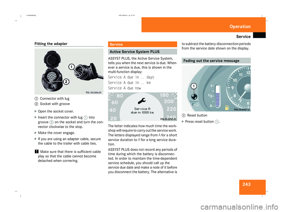
Fitting the adapter
1
Connector with lug
2 Socket with groove
X Open the socket cover.
X Insert the connector with lug 1into
groove 2on the socket and turn the con-
nector clockwise to the stop.
X Make the cover engage.
X If you are using an adapter cable, secure
the cable to the trailer with cable ties.
! Make sure that there is sufficient cable
play so that the cable cannot become
detached when cornering. Service
Active Service System PLUS
ASSYST PLUS, the Active Service System,
tells you when the next service is due. When-
ever a service is due, this is shown in the
multi-function display:
Service A due in .. days
Service A due in .. km
Service A due now The letter indicates how much time the work-
shop will require to carry out the service work.
The letters displayed range from
Afor a short
service duration to Hfor a long service dura-
tion.
ASSYST PLUS does not record any periods of
time during which the battery is disconnec-
ted. In order to maintain the time-dependent
service schedule, you should call up the
service due date and make a note of it before
you disconnect the battery. The alternative is to subtract the battery-disconnection periods
from the service date shown on the display. Fading out the service message
1
Reset button
X Press reset button 1. Operation
211_AKB; 2; 5, en-GB
mkalafa,
Version: 2.9.4
2008-02-29T16:57:07+01:00 - Seite 243 ZDateiname: 6515_3416_02_buchblock.pdf; preflight
Page 259 of 401
Where will I find...?
256
Removing the "Minispare" emergency
spare wheel*/collapsible emergency
spare wheel or spare wheel*
X Saloon: remove the luggage well
(Y page 256).
X Estate: remove the luggage compartment
floor (Y page 194).
X Turn fastening element 3anti-clockwise.
X Remove the "Minispare" emergency spare
wheel/collapsible emergency spare wheel
or the spare wheel 2.
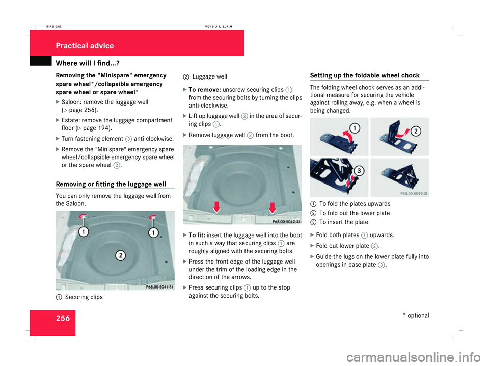
Removing or fitting the luggage well You can only remove the luggage well from
the Saloon. 1
Securing clips 2
Luggage well
X To remove: unscrew securing clips 1
from the securing bolts by turning the clips
anti-clockwise.
X Lift up luggage well 2in the area of secur-
ing clips 1.
X Remove luggage well 2from the boot. X
To fit: insert the luggage well into the boot
in such a way that securing clips 1are
roughly aligned with the securing bolts.
X Press the front edge of the luggage well
under the trim of the loading edge in the
direction of the arrows.
X Press securing clips 1up to the stop
against the securing bolts. Setting up the foldable wheel chock The folding wheel chock serves as an addi-
tional measure for securing the vehicle
against rolling away, e.g. when a wheel is
being changed.
1
To fold the plates upwards
2 To fold out the lower plate
3 To insert the plate
X Fold both plates 1upwards.
X Fold out lower plate 2.
X Guide the lugs on the lower plate fully into
openings in base plate 3.Practical advice
* optional
211_AKB; 2; 5, en-GB
mkalafa,
Version: 2.9.4 2008-02-29T16:57:07+01:00 - Seite 256Dateiname: 6515_3416_02_buchblock.pdf; preflight