2008 MERCEDES-BENZ CLS COUPE light
[x] Cancel search: lightPage 266 of 329
Troubleshooting
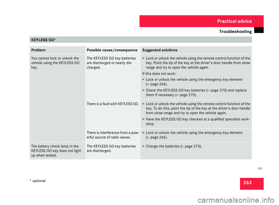
263KEYLESS GO*
Problem Possible cause/consequence Suggested solutions
You cannot lock or unlock the
vehicle using the KEYLESS GO
key. The KEYLESS GO key batteries
are discharged or nearly dis-
charged. X
Lock or unlock the vehicle using the remote control function of the
key.
Point the tip of the key at the driver's door handle from close
range and try to open the vehicle again.
If this does not work:
X Lock or unlock the vehicle using the emergency key element
(Y page 266).
X Check the KEYLESS GO key batteries (Y page 270) and replace
them if necessary (Y page 270). There is a fault with KEYLESS GO. X
Lock or unlock the vehicle using the remote control function of the
key.
To do this, point the tip of the key at the driver's door handle
from close range and try to open the vehicle again.
X Have the KEYLESS GO key checked at a qualified specialist work-
shop. There is interference from a pow-
erful source of radio waves. X
Lock or unlock the vehicle using the emergency key element
(Y page 266). The battery check lamp in the
KEYLESS GO key does not light
up when tested. The KEYLESS GO key batteries
are discharged. X
Change the batteries ( Y page 270). Practical advice
* optional
219_AKB; 2; 4, en-GB
mkalafa,
2007-11-13T09:28:36+01:00 - Seite 263 Z
Page 273 of 329
Changing the batteries
270 Key or KEYLESS GO key*
Checking the batteries X
Press the j or k button.
The batteries are in order if the battery
charge indicator lamp lights up briefly.
Changing the batteries You require two CR 2025 3V cell batteries.
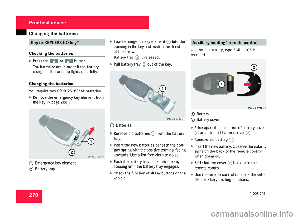
X
Remove the emergency key element from
the key (Y page 266). 1
Emergency key element
2 Battery tray X
Insert emergency key element 1 into the
opening in the key and push in the direction
of the arrow.
Battery tray 2 is released.
X Pull battery tray 2 out of the key. 1
Batteries
X Remove old batteries 1 from the battery
tray.
X Insert the new batteries beneath the con-
tact spring with the positive terminal facing
upwards. Use a lint-free cloth to do so.
X Push the battery tray back into the key
housing until the battery tray engages.
X Check the function of all key buttons on the
vehicle. Auxiliary heating* remote control
One 6V pin battery, type 2CR11108 is
required. 1
Battery
2 Battery cover
X Prise apart the side arms of battery cover
2 and slide off battery cover 2.
X Remove old battery 1.
X Insert the new battery. Observe the polarity
signs on the back of the remote control
when doing so.
X Slide battery cover 2 back onto the
remote control.
X Use the remote control to check the vehi-
cle's auxiliary heating functions. Practical advice
* optional
219_AKB; 2; 4, en-GB
mkalafa,
2007-11-13T09:28:36+01:00 - Seite 270
Page 275 of 329
Changing the bulbs
272
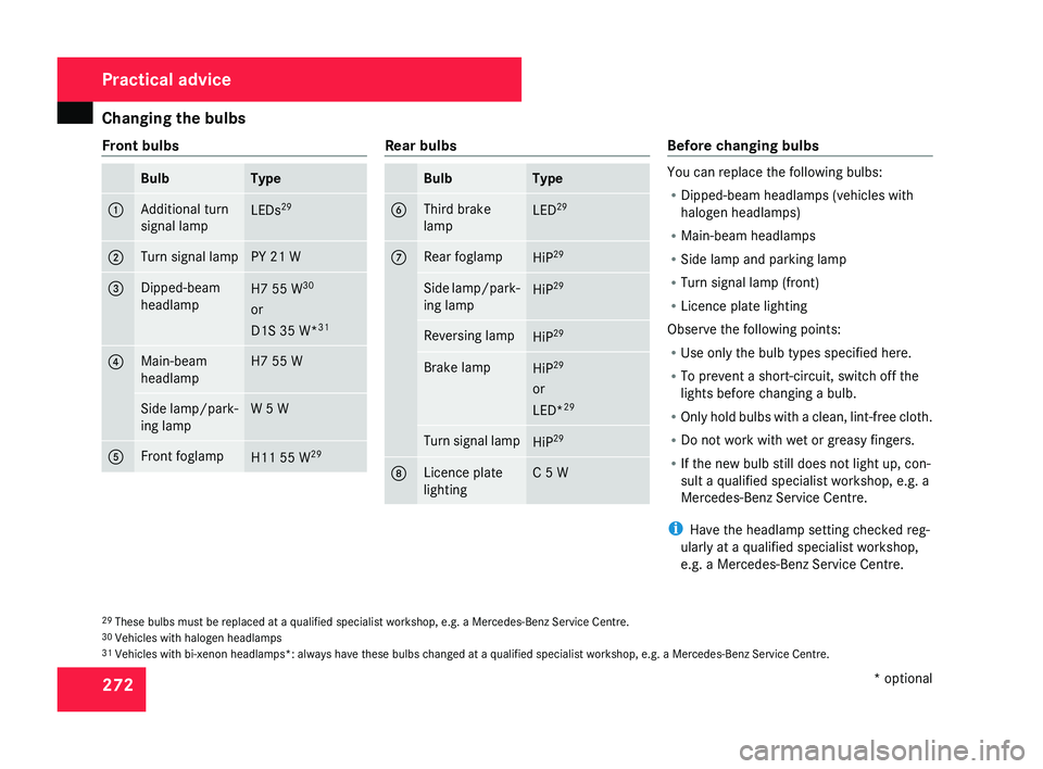
Front bulbs Bulb Type
1 Additional turn
signal lamp
LEDs
29 2 Turn signal lamp PY 21 W
3 Dipped-beam
headlamp
H7 55 W
30
or
D1S 35 W* 31 4 Main-beam
headlamp H7 55 W
Side lamp/park-
ing lamp W 5 W
5 Front foglamp
H11 55 W
29 Rear bulbs
Bulb Type
6 Third brake
lamp
LED
29 7 Rear foglamp
HiP
29 Side lamp/park-
ing lamp
HiP
29 Reversing lamp
HiP
29 Brake lamp
HiP
29
or
LED* 29 Turn signal lamp
HiP
29 8 Licence plate
lighting C 5 W Before changing bulbs
You can replace the following bulbs:
R
Dipped-beam headlamps (vehicles with
halogen headlamps)
R Main-beam headlamps
R Side lamp and parking lamp
R Turn signal lamp (front)
R Licence plate lighting
Observe the following points:
R Use only the bulb types specified here.
R To prevent a short-circuit, switch off the
lights before changing a bulb.
R Only
hold bulbs with a clean, lint-free cloth.
R Do not work with wet or greasy fingers.
R If the new bulb still does not light up, con-
sult a qualified specialist workshop, e.g. a
Mercedes-Benz Service Centre.
i Have the headlamp setting checked reg-
ularly at a qualified specialist workshop,
e.g. a Mercedes-Benz Service Centre.
29 These bulbs must be replaced at a qualified specialist workshop, e.g. a Mercedes-Benz Service Centre.
30 Vehicles with halogen headlamps
31 Vehicles with bi-xenon headlamps*: always have these bulbs changed at a qualified specialist workshop, e.g. a Mercedes-Benz Service Centre. Practical advice
* optional
219_AKB; 2; 4, en-GB
mkalafa,
2007-11-13T09:28:36+01:00 - Seite 272
Page 276 of 329
Changing the bulbs
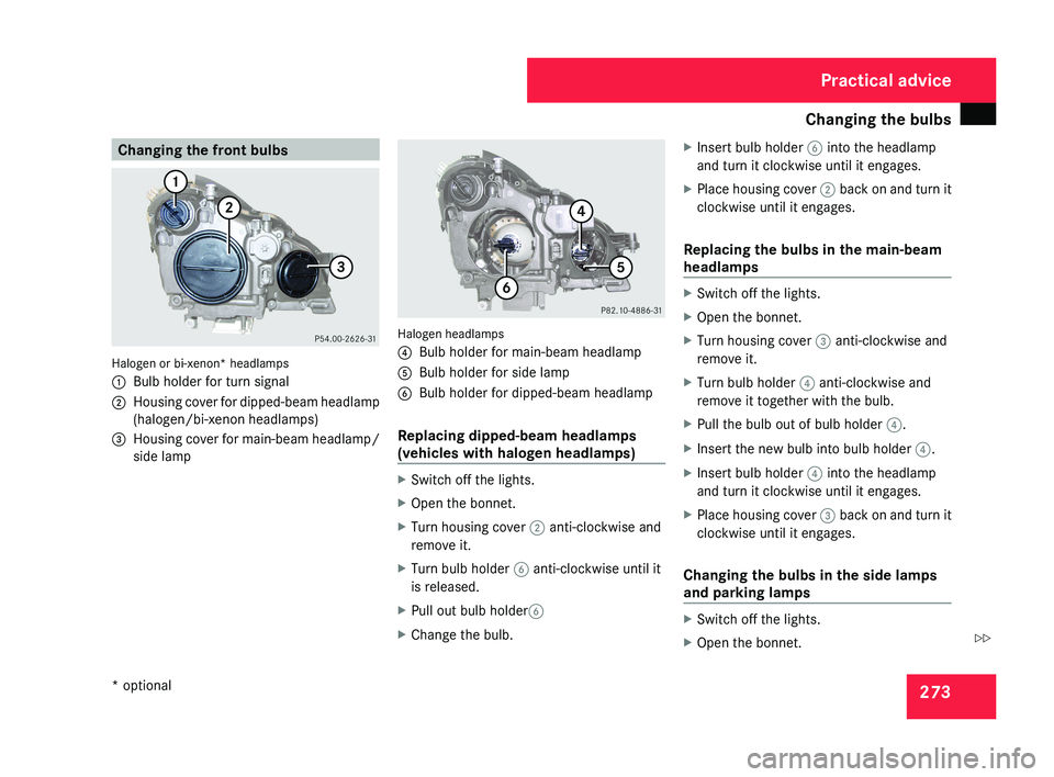
273Changing the front bulbsHalogen or bi-xenon* headlamps
1
Bulb holder for turn signal
2 Housing cover for dipped-beam headlamp
(halogen/bi-xenon headlamps)
3 Housing cover for main-beam headlamp/
side lamp
Halogen headlamps
4Bulb holder for main-beam headlamp
5 Bulb holder for side lamp
6 Bulb holder for dipped-beam headlamp
Replacing dipped-beam headlamps
(vehicles with halogen headlamps)
X Switch off the lights.
X Open the bonnet.
X Turn housing cover 2 anti-clockwise and
remove it.
X Turn bulb holder 6 anti-clockwise until it
is released.
X Pull out bulb holder 6
X Change the bulb. X
Insert bulb holder 6 into the headlamp
and turn it clockwise until it engages.
X Place housing cover 2 back on and turn it
clockwise until it engages.
Replacing the bulbs in the main-beam
headlamps
X Switch off the lights.
X Open the bonnet.
X Turn housing cover 3 anti-clockwise and
remove it.
X Turn bulb holder 4 anti-clockwise and
remove it together with the bulb.
X Pull the bulb out of bulb holder 4.
X Insert the new bulb into bulb holder 4.
X Insert bulb holder 4 into the headlamp
and turn it clockwise until it engages.
X Place housing cover 3 back on and turn it
clockwise until it engages.
Changing the bulbs in the side lamps
and parking lamps
X Switch off the lights.
X Open the bonnet.
Practical advice
* optional
219_AKB; 2; 4, en-GB
mkalafa,
2007-11-13T09:28:36+01:00 - Seite 273
Z
Page 277 of 329
Changing the bulbs
274
X
Turn housing cover 3 anti-clockwise and
remove it.
X Turn main-beam headlamp bulb holder 4
anti-clockwise until it disengages and then
remove it together with the bulb.
X Turn the bulb anti-clockwise, applying
slight pressure, and remove it from bulb
holder 5.
X Insert the new bulb into bulb holder 5 and
turn it clockwise.
X Pull out bulb holder 5.
X Insert main-beam headlamp bulb
holder 4 into the headlamp and turn it
clockwise until it engages.
X Place housing cover 3 back on and turn it
clockwise until it engages.
Replacing the turn signal lamps X
Switch off the lights.
X Open the bonnet.
X Turn bulb holder 1 anti-clockwise and
remove it along with the bulb.
X Turn the bulb anti-clockwise, applying
slight pressure, and remove it from bulb
holder 1. X
Insert the new bulb into bulb holder 1 and
turn it clockwise.
X Insert bulb holder 1 into the headlamp
and turn it clockwise until it engages. Changing the rear bulbs
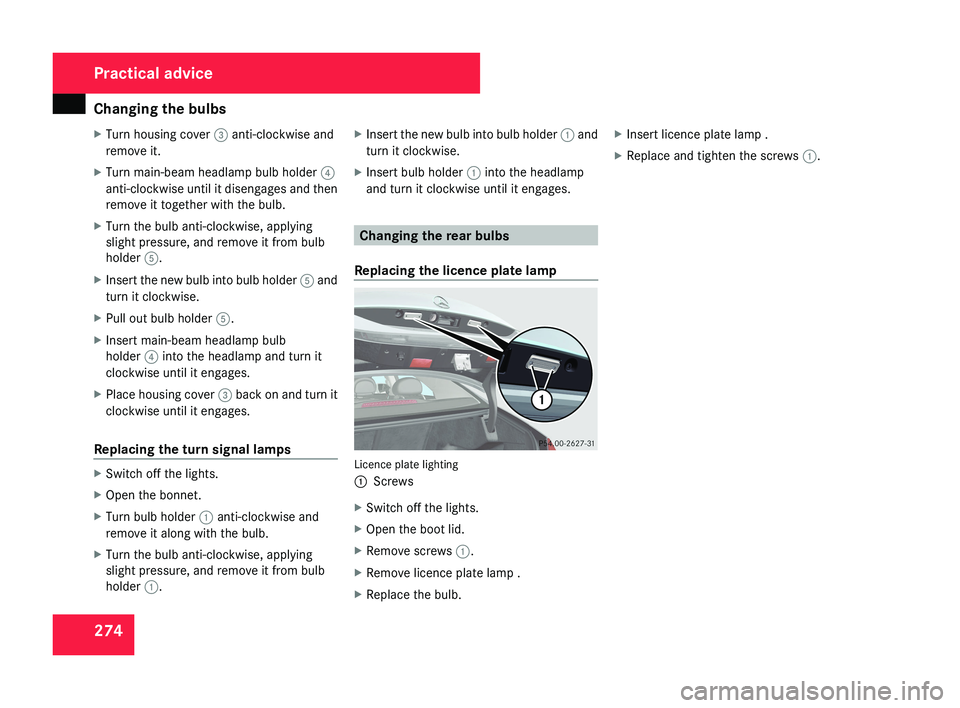
Replacing the licence plate lamp Licence plate lighting
1
Screws
X Switch off the lights.
X Open the boot lid.
X Remove screws 1.
X Remove licence plate lamp .
X Replace the bulb. X
Insert licence plate lamp .
X Replace and tighten the screws 1.Practical advice
219_AKB; 2; 4, en-GB
mkalafa,
2007-11-13T09:28:36+01:00 - Seite 274
Page 282 of 329
Flat tyre
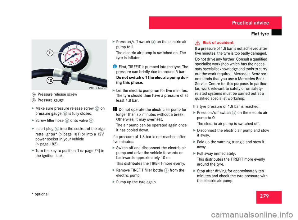
279a
Pressure release screw
b Pressure gauge
X Make sure pressure release screw a on
pressure gauge b is fully closed.
X Screw filler hose 8 onto valve 9.
X Insert plug 5 into the socket of the ciga-
rette lighter* (Y page 181) or into a 12V
power socket in your vehicle
(Y page 182).
X Turn the key to position 1 (Y page 74) in
the ignition lock. X
Press on/off switch 4 on the electric air
pump to I.
The electric air pump is switched on. The
tyre is inflated.
i First, TIREFIT is pumped into the tyre. The
pressure can briefly rise to around 5 bar.
Do not switch off the electric pump dur-
ing this phase.
X Let the electric pump run for five minutes.
The tyre should then have a pressure of at
least 1.8 bar.
! Do not operate the electric air pump for
longer than six minutes without a break.
Otherwise, it may overheat.
The air pump can be operated again once
it has cooled down.
If a pressure of 1.8 bar is not reached after
five minutes:
X Switch off and disconnect the electric air
pump and drive the vehicle forwards or
backwards approximately 10 m.
This distributes the TIREFIT more evenly.
X Remove TIREFIT filler bottle 1 from the
electric pump.
X Pump up the tyre again.
G Risk of accident
If a pressure of 1.8 bar is not achieved after
five minutes, the tyre is too badly damaged.
Do not drive any further. Consult a qualified
specialist workshop which has the neces-
sary specialist knowledge and tools to carry
out the work required. Mercedes-Benz rec-
ommends that you use a Mercedes-Benz
Service Centre for this purpose. In particu-
lar, work relevant to safety or on safety-
related systems must be carried out at a
qualified specialist workshop.
If a tyre pressure of 1.8 bar is reached:
X Press on/off switch 4 on the electric air
pump to 0.
The electric air pump is switched off.
X Disconnect the electric air pump and stow
it away.
X Fold up the warning triangle and stow it
away.
X Pull away immediately.
This distributes the TIREFIT more evenly
around the tyre.
X Stop after driving for approximately ten
minutes and check the tyre pressure with
the electric air pump.
Practical advice
* optional
219_AKB; 2; 4, en-GB
mkalafa,
2007-11-13T09:28:36+01:00 - Seite 279
Page 284 of 329

Flat tyre
2817
Valve
8 Filler hose
X Remove the cap from valve 7 on the faulty
tyre.
X Screw filler hose 8 onto valve 7.
X Insert plug 4 into the socket of the ciga-
rette lighter* (Y page 181) or into a 12V
power socket in your vehicle
(Y page 182).
X Turn the key to position 1 in the ignition
lock. X
Press on/off switch 3 on the electric air
pump to I.
The electric air pump is switched on. The
tyre is inflated.
i First, TIREFIT is pumped into the tyre. The
pressure can briefly rise to around 5 bar.
Do not switch off the electric pump dur-
ing this phase.
X Let the electric pump run for five minutes.
The tyre should then have a pressure of at
least 1.8 bar.
! Do not operate the electric air pump for
longer than six minutes without a break.
Otherwise, it may overheat.
The air pump can be operated again once
it has cooled down.
If a pressure of 1.8 bar is not reached after
five minutes:
X Switch off and disconnect the electric air
pump and drive the vehicle forwards or
backwards approximately 10 m.
This distributes the TIREFIT more evenly.
X Remove TIREFIT filler bottle 1 from the
electric pump.
X Pump up the tyre again.
G Risk of accident
If a pressure of 1.8 bar is not achieved after
five minutes, the tyre is too badly damaged.
Do not drive any further. Consult a qualified
specialist workshop which has the neces-
sary specialist knowledge and tools to carry
out the work required. Mercedes-Benz rec-
ommends that you use a Mercedes-Benz
Service Centre for this purpose. In particu-
lar, work relevant to safety or on safety-
related systems must be carried out at a
qualified specialist workshop.
If a tyre pressure of 1.8 bar is reached:
X Press on/off switch 3 on the electric air
pump to 0.
The electric air pump is switched off.
X Disconnect the electric air pump and stow
it away.
X Fold up the warning triangle and stow it
away.
X Pull away immediately.
This distributes the TIREFIT more evenly
around the tyre.
X Stop after driving for approximately ten
minutes and check the tyre pressure with
the electric air pump.
Practical advice
* optional
219_AKB; 2; 4, en-GB
mkalafa,
2007-11-13T09:28:36+01:00 - Seite 281
Page 289 of 329

Flat tyre
286
X
Screw union nut 5 on air hose 4 onto the
valve.
X Insert plug 3 into the cigarette lighter
socket* ( Y page 181) or into a 12V socket
in your vehicle ( Y page 182).
X Make sure that the key is in position 2 in
the ignition lock.
X Press on/off switch 2 on the electric air
pump to I.
The electric air pump is switched on. The
tyre is inflated.
X When a tyre pressure of 3.5 bar has been
reached, press 0 on the electric air pump
switch.
The electric air pump is switched off.
! Do not operate the electric air pump for
longer than six minutes without a break.
Otherwise, it may overheat.
The air pump can be operated again once
it has cooled down.
If the tyre pressure is higher than 3.5 bar: X
Open the pressure release screw on the
pressure gauge until the tyre pressure is
correct.
X Disconnect the electric air pump and stow
it away.
Lowering the vehicle X
Lower the vehicle. To do this, turn the crank
of the jack anti-clockwise until the vehicle
is standing firmly on the ground again.
X Place the jack to one side. 1
– 5 Wheel bolts
X Tighten the wheel bolts evenly in a cross-
wise pattern in the sequence indica-
ted ( 1 to 5). The tightening torque must
be 130 Nm. G
Risk of accident
Have the tightening torque checked imme-
diately after a wheel is changed. The wheels
could work loose if they are not tightened
to a tightening torque of 130 Nm.
X Turn the jack back to its initial position and
store it and the rest of the vehicle tool kit
in the boot.
Vehicles with the "Minispare"/collapsible
emergency spare wheel*:
X Wrap the faulty wheel in the protective film
provided with the "Minispare"/collapsible
emergency spare wheel* and transport the
wheel in the boot.
or
X Depending on the size of the wheel, the
faulty wheel may also be secured in the
spare wheel recess. In this case, the stow-
age well casing will have to be removed
from the spare wheel well and stowed in the
boot.
i Do not activate the tyre pressure moni-
tor* until the deflated tyre has been
removed from the vehicle. Practical advice
* optional
219_AKB; 2; 4, en-GB
mkalafa,
2007-11-13T09:28:36+01:00 - Seite 286