2008 INFINITI QX56 battery
[x] Cancel search: batteryPage 3533 of 4083
STR-4
< PREPARATION >
PREPARATION
PREPARATION
PREPARATION
Special Service ToolINFOID:0000000001538875
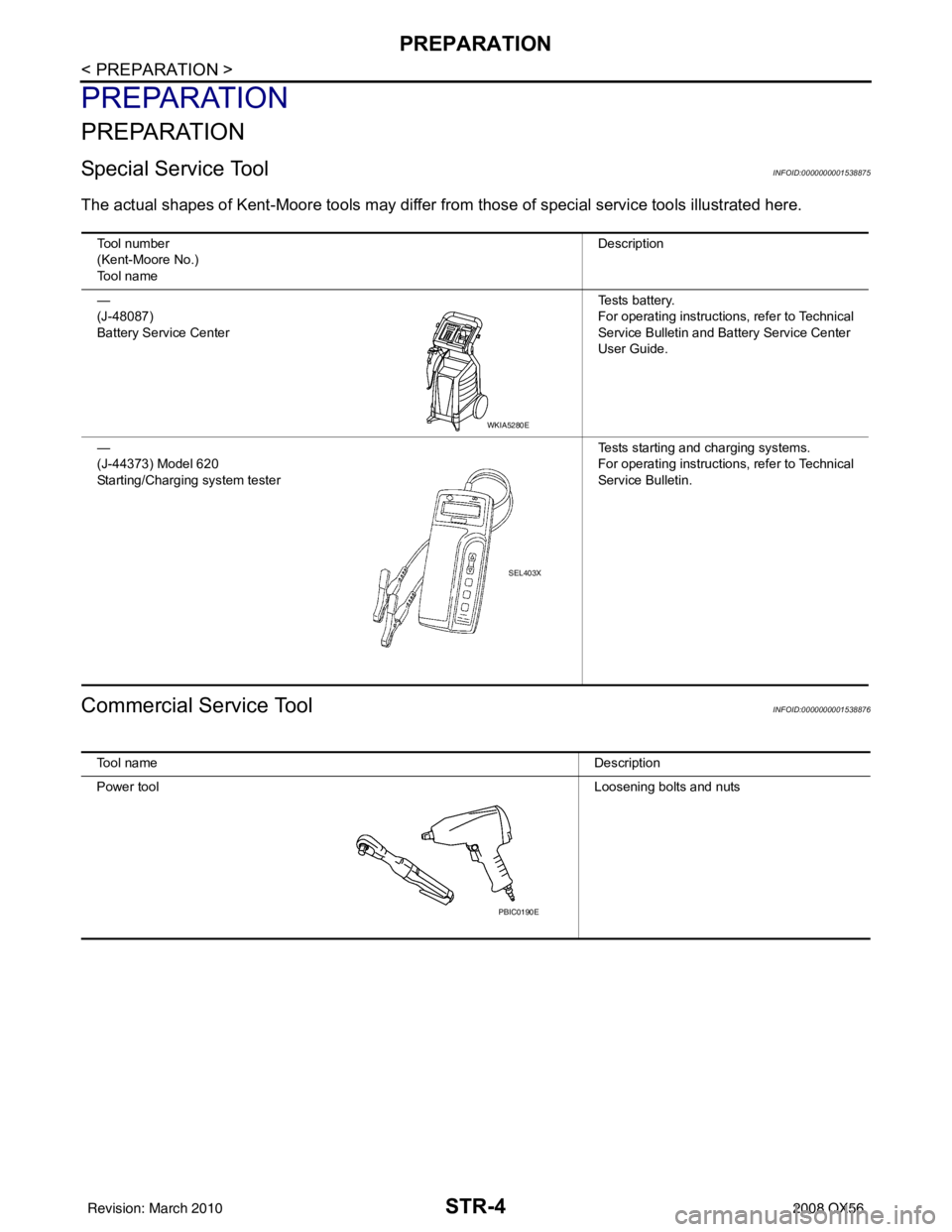
The actual shapes of Kent-Moore tools may differ from those of special service tools illustrated here.
Commercial Service ToolINFOID:0000000001538876
Tool number
(Kent-Moore No.)
Tool name Description
—
(J-48087)
Battery Service Center Te s t s b a t t e r y.
For operating instructions, refer to Technical
Service Bulletin and Battery Service Center
User Guide.
—
(J-44373) Model 620
Starting/Charging system tester Tests starting and charging systems.
For operating instructions, refer to Technical
Service Bulletin.
WKIA5280E
SEL403X
Tool name
Description
Power tool Loosening bolts and nuts
PBIC0190E
Revision: March 2010 2008 QX56
Page 3535 of 4083
STR-6
< BASIC INSPECTION >
DIAGNOSIS AND REPAIR WORKFLOW
NOTE:
To ensure a complete and thorough diagnosis, the battery, starter motor and alternator test segments must be
done as a set from start to finish.
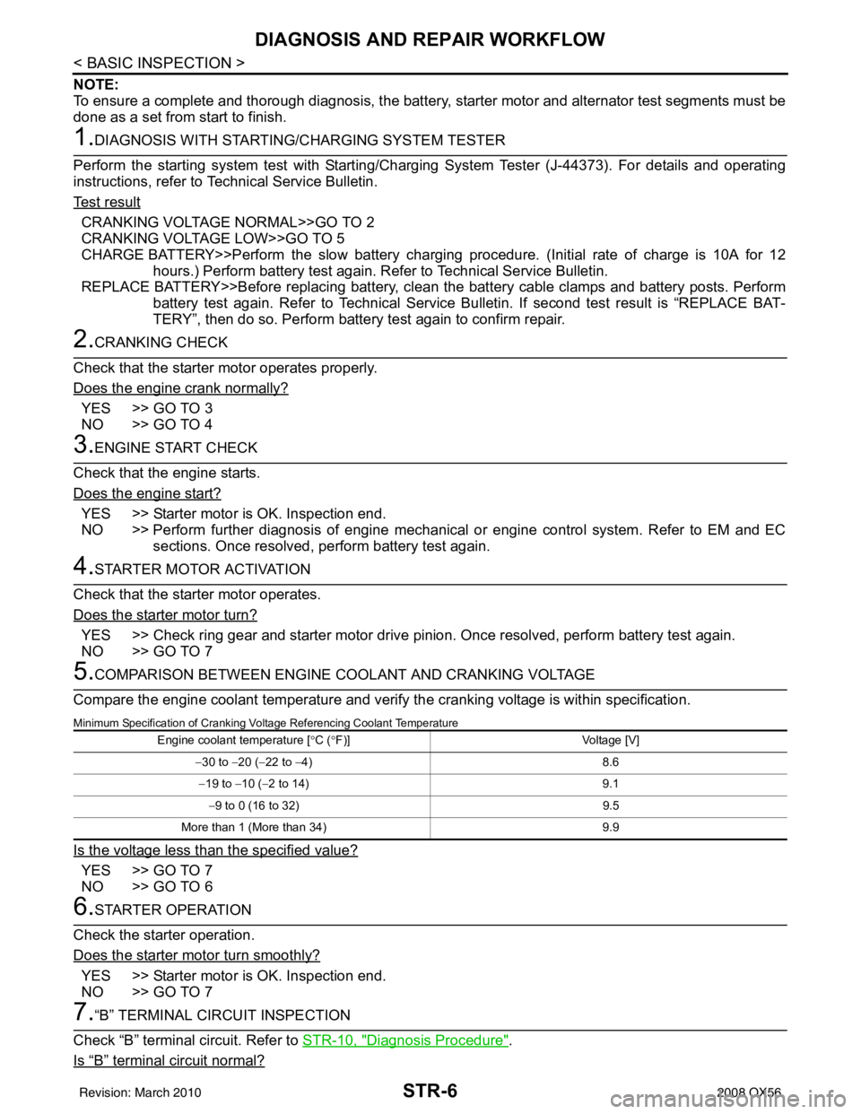
1.DIAGNOSIS WITH STARTING/CHARGING SYSTEM TESTER
Perform the starting system test with Starting/Charging System Tester (J-44373). For details and operating
instructions, refer to Technical Service Bulletin.
Te s t r e s u l t
CRANKING VOLTAGE NORMAL>>GO TO 2
CRANKING VOLTAGE LOW>>GO TO 5
CHARGE BATTERY>>Perform the slow battery charging procedure. (Initial rate of charge is 10A for 12
hours.) Perform battery test again. Refer to Technical Service Bulletin.
REPLACE BATTERY>>Before replacing battery, clean t he battery cable clamps and battery posts. Perform
battery test again. Refer to Technical Service Bulletin. If second test result is “REPLACE BAT-
TERY”, then do so. Perform battery test again to confirm repair.
2.CRANKING CHECK
Check that the starter motor operates properly.
Does the engine crank normally?
YES >> GO TO 3
NO >> GO TO 4
3.ENGINE START CHECK
Check that the engine starts.
Does the engine start?
YES >> Starter motor is OK. Inspection end.
NO >> Perform further diagnosis of engine mechanical or engine control system. Refer to EM and EC sections. Once resolved, perform battery test again.
4.STARTER MOTOR ACTIVATION
Check that the starter motor operates.
Does the starter motor turn?
YES >> Check ring gear and starter motor drive pinion. Once resolved, perform battery test again.
NO >> GO TO 7
5.COMPARISON BETWEEN ENGINE COOLANT AND CRANKING VOLTAGE
Compare the engine coolant temperature and verify the cranking voltage is within specification.
Minimum Specification of Cranking Voltage Referencing Coolant Temperature
Is the voltage less than the specified value?
YES >> GO TO 7
NO >> GO TO 6
6.STARTER OPERATION
Check the starter operation.
Does the starter motor turn smoothly?
YES >> Starter motor is OK. Inspection end.
NO >> GO TO 7
7.“B” TERMINAL CIRCUIT INSPECTION
Check “B” terminal circuit. Refer to STR-10, "
Diagnosis Procedure".
Is
“B” terminal circuit normal?
Engine coolant temperature [ °C ( °F)] Voltage [V]
− 30 to − 20 (−22 to − 4) 8.6
− 19 to −10 ( −2 to 14) 9.1
− 9 to 0 (16 to 32) 9.5
More than 1 (More than 34) 9.9
Revision: March 2010 2008 QX56
Page 3536 of 4083
DIAGNOSIS AND REPAIR WORKFLOWSTR-7
< BASIC INSPECTION >
C
DE
F
G H
I
J
K L
M A
STR
NP
O
YES >> GO TO 8
NO >> Repair as needed.
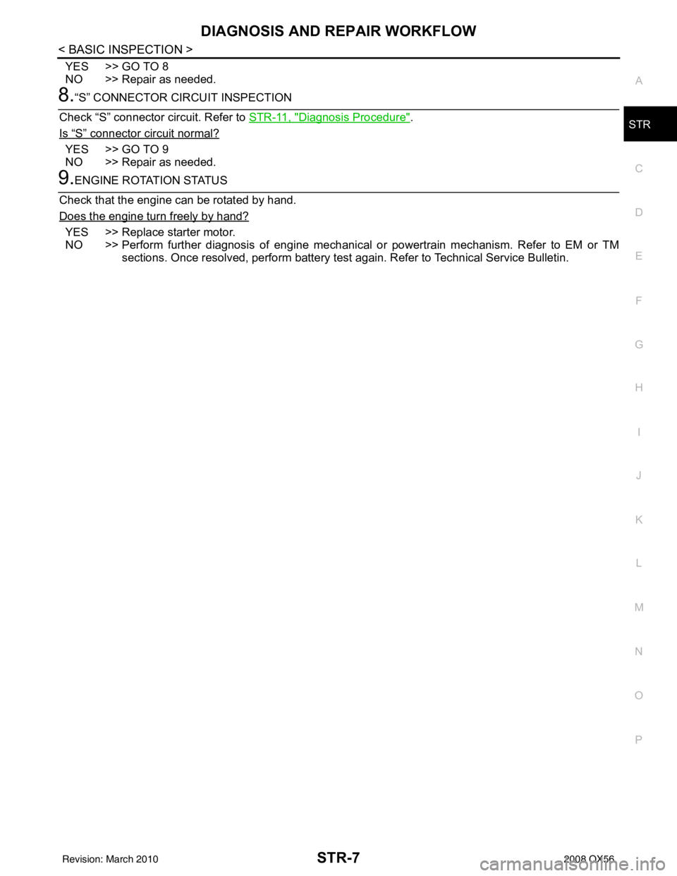
8.“S” CONNECTOR CIRCUIT INSPECTION
Check “S” connector circuit. Refer to STR-11, "
Diagnosis Procedure".
Is
“S” connector circuit normal?
YES >> GO TO 9
NO >> Repair as needed.
9.ENGINE ROTATION STATUS
Check that the engine can be rotated by hand.
Does the engine turn freely by hand?
YES >> Replace starter motor.
NO >> Perform further diagnosis of engine mechanical or powertrain mechanism. Refer to EM or TM
sections. Once resolved, perform battery test again. Refer to Technical Service Bulletin.
Revision: March 2010 2008 QX56
Page 3537 of 4083
STR-8
< FUNCTION DIAGNOSIS >
STARTING SYSTEM
FUNCTION DIAGNOSIS
STARTING SYSTEM
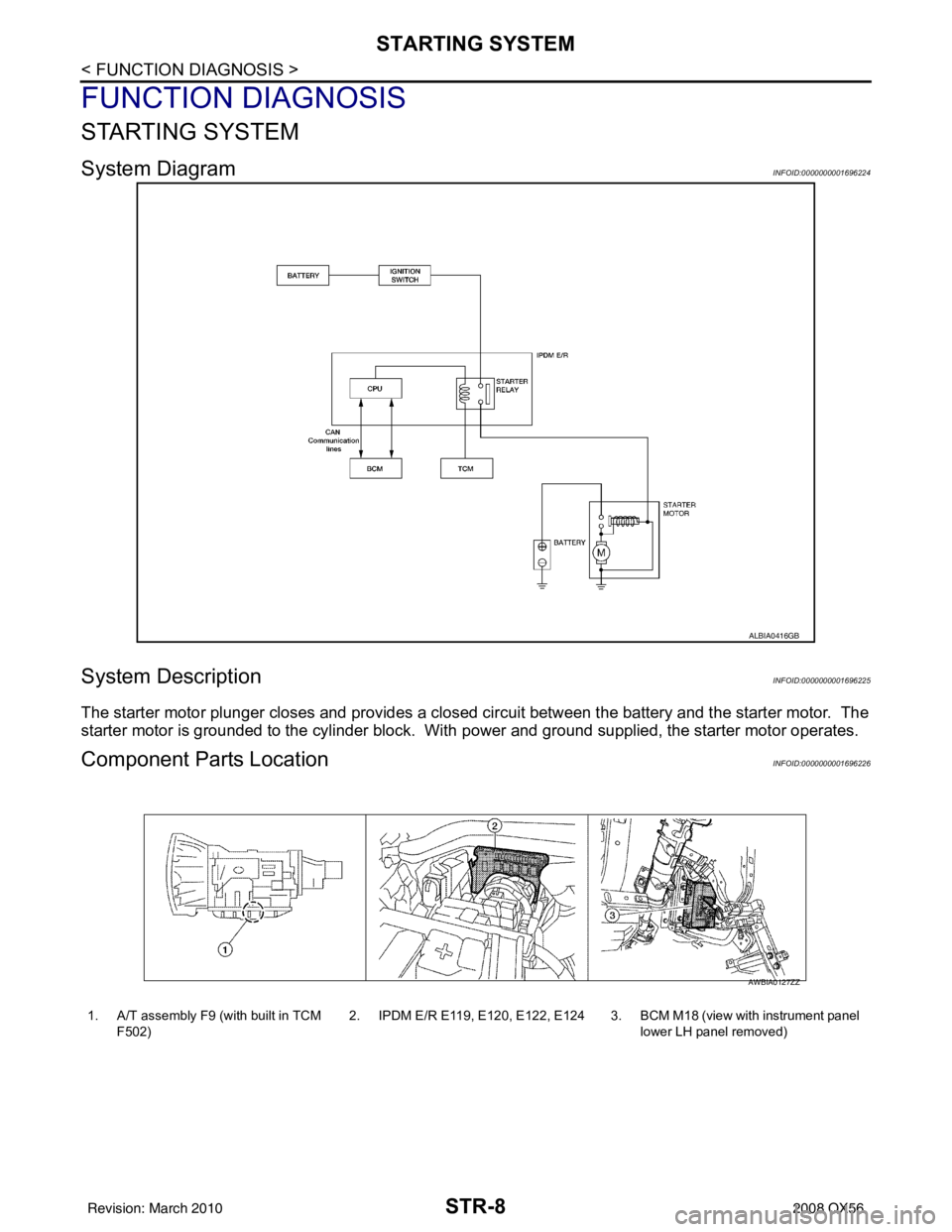
System DiagramINFOID:0000000001696224
System DescriptionINFOID:0000000001696225
The starter motor plunger closes and provides a closed circuit between the battery and the starter motor. The
starter motor is grounded to the cylinder block. With power and ground supplied, the starter motor operates.
Component Parts LocationINFOID:0000000001696226
ALBIA0416GB
1. A/T assembly F9 (with built in TCM
F502) 2. IPDM E/R E119, E120, E122, E124 3. BCM M18 (view with instrument panel
lower LH panel removed)
AWBIA0127ZZ
Revision: March 2010 2008 QX56
Page 3538 of 4083
STARTING SYSTEMSTR-9
< FUNCTION DIAGNOSIS >
C
DE
F
G H
I
J
K L
M A
STR
NP
O
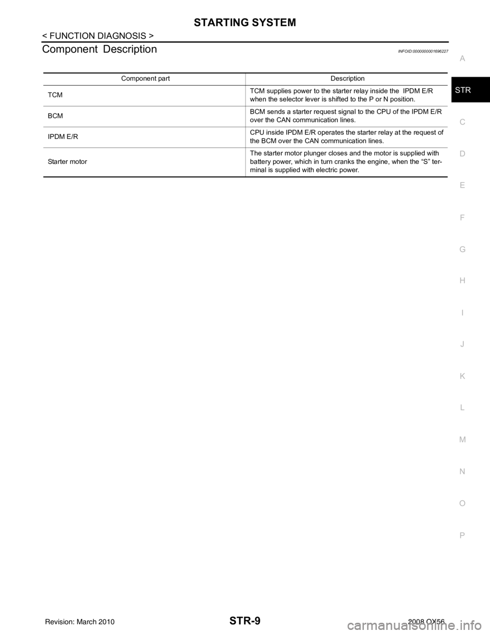
Component DescriptionINFOID:0000000001696227
Component part
Description
TCM TCM supplies power to the starter relay inside the IPDM E/R
when the selector lever is shifted to the P or N position.
BCM BCM sends a starter request signal to the CPU of the IPDM E/R
over the CAN communication lines.
IPDM E/R CPU inside IPDM E/R operates the starter relay at the request of
the BCM over the CAN communication lines.
Starter motor The starter motor plunger closes and the motor is supplied with
battery power, which in turn cranks the engine, when the “S” ter-
minal is supplied with electric power.
Revision: March 2010
2008 QX56
Page 3539 of 4083
STR-10
< COMPONENT DIAGNOSIS >
B TERMINAL CIRCUIT
COMPONENT DIAGNOSIS
B TERMINAL CIRCUIT
DescriptionINFOID:0000000001696228
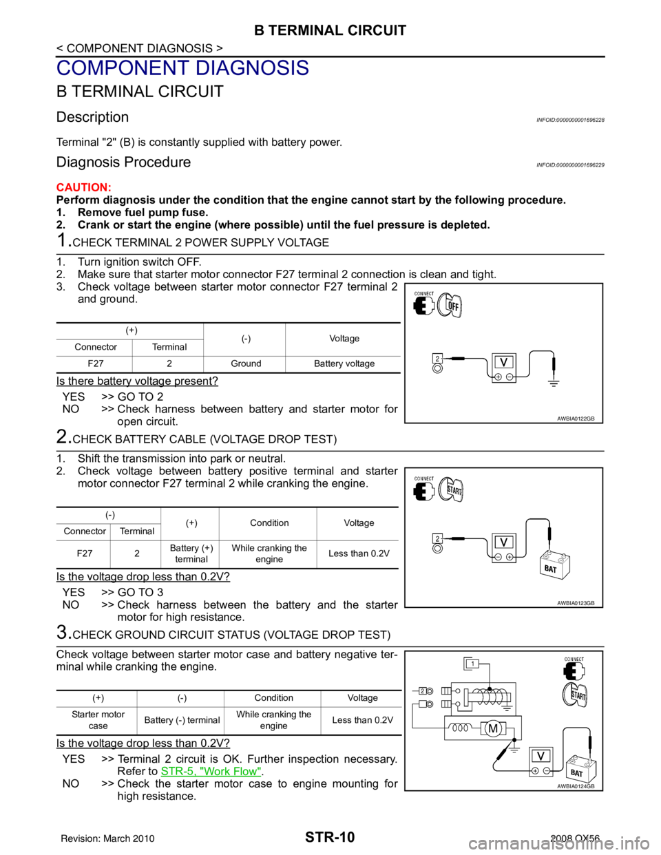
Terminal "2" (B) is constantly supplied with battery power.
Diagnosis ProcedureINFOID:0000000001696229
CAUTION:
Perform diagnosis under the condition that the engine cannot start by the following procedure.
1. Remove fuel pump fuse.
2. Crank or start the engine (where possible) until the fuel pressure is depleted.
1.CHECK TERMINAL 2 POWER SUPPLY VOLTAGE
1. Turn ignition switch OFF.
2. Make sure that starter motor connector F27 terminal 2 connection is clean and tight.
3. Check voltage between starter motor connector F27 terminal 2
and ground.
Is there battery voltage present?
YES >> GO TO 2
NO >> Check harness between battery and starter motor for open circuit.
2.CHECK BATTERY CABLE (VOLTAGE DROP TEST)
1. Shift the transmission into park or neutral.
2. Check voltage between battery positive terminal and starter motor connector F27 terminal 2 while cranking the engine.
Is the voltage drop less than 0.2V?
YES >> GO TO 3
NO >> Check harness between the battery and the starter motor for high resistance.
3.CHECK GROUND CIRCUIT STATUS (VOLTAGE DROP TEST)
Check voltage between starter motor case and battery negative ter-
minal while cranking the engine.
Is the voltage drop less than 0.2V?
YES >> Terminal 2 circuit is OK. Further inspection necessary. Refer to STR-5, "
Work Flow".
NO >> Check the starter motor case to engine mounting for
high resistance.
(+) (-) Voltage
Connector Terminal
F27 2 Ground Battery voltage
AWBIA0122GB
(-) (+) Condition Voltage
Connector Terminal
F27 2 Battery (+)
terminal While cranking the
engine Less than 0.2V
AWBIA0123GB
(+)
(-)Condition Voltage
Starter motor case Battery (-) terminal While cranking the
engine Less than 0.2V
AWBIA0124GB
Revision: March 2010
2008 QX56
Page 3540 of 4083
S CONNECTOR CIRCUITSTR-11
< COMPONENT DIAGNOSIS >
C
DE
F
G H
I
J
K L
M A
STR
NP
O
S CONNECTOR CIRCUIT
DescriptionINFOID:0000000001696230
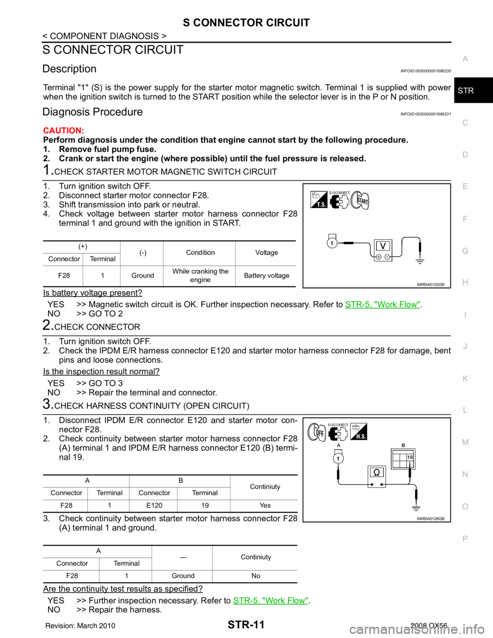
Terminal "1" (S) is the power supply for the starter mo
tor magnetic switch. Terminal 1 is supplied with power
when the ignition switch is turned to the START position while the selector lever is in the P or N position.
Diagnosis ProcedureINFOID:0000000001696231
CAUTION:
Perform diagnosis under the cond ition that engine cannot start by the following procedure.
1. Remove fuel pump fuse.
2. Crank or start the engine (where possi ble) until the fuel pressure is released.
1.CHECK STARTER MOTOR MAGNETIC SWITCH CIRCUIT
1. Turn ignition switch OFF.
2. Disconnect starter motor connector F28.
3. Shift transmission into park or neutral.
4. Check voltage between starter motor harness connector F28 terminal 1 and ground with the ignition in START.
Is battery voltage present?
YES >> Magnetic switch circuit is OK. Further inspection necessary. Refer to STR-5, "Work Flow".
NO >> GO TO 2
2.CHECK CONNECTOR
1. Turn ignition switch OFF.
2. Check the IPDM E/R harness connector E120 and starter motor harness connector F28 for damage, bent pins and loose connections.
Is the inspection result normal?
YES >> GO TO 3
NO >> Repair the terminal and connector.
3.CHECK HARNESS CONTI NUITY (OPEN CIRCUIT)
1. Disconnect IPDM E/R connector E120 and starter motor con- nector F28.
2. Check continuity between starter motor harness connector F28 (A) terminal 1 and IPDM E/R harness connector E120 (B) termi-
nal 19.
3. Check continuity between starter motor harness connector F28 (A) terminal 1 and ground.
Are the continuity test results as specified?
YES >> Further inspection necessary. Refer to STR-5, "Work Flow".
NO >> Repair the harness.
(+) (-)Condition Voltage
Connector Terminal
F28 1 Ground While cranking the
engine Battery voltage
AWBIA0125GB
AB
Continiuty
Connector Terminal Connector Terminal
F28 1E120 19 Yes
A —Continiuty
Connector Terminal
F28 1Ground No
AWBIA0126GB
Revision: March 2010 2008 QX56
Page 3551 of 4083

TM-4
Precaution for Supplemental Restraint System
(SRS) "AIR BAG" and "SEAT BELT PRE-TEN-
SIONER" ................................................................
173
Precaution Necessary for Steering Wheel Rota-
tion After Battery Disconnect .................................
173
Precaution for On Board Diagnosis (OBD) System
of A/T and Engine ..................................................
174
Precaution .............................................................174
Service Notice or Precaution .................................175
PREPARATION ..........................................176
PREPARATION .............................................. .176
Special Service Tool ............................................ ..176
Commercial Service Tool ......................................177
ON-VEHICLE MAINTENANCE ..................178
A/T FLUID ....................................................... .178
Checking the A/T Fluid (ATF) .............................. ..178
Changing the A/T Fluid (ATF) ................................180
A/T FLUID COOLER ........................................182
A/T Fluid Cooler Cleaning ................................... ..182
Inspection ..............................................................184
STALL TEST ....................................................185
Inspection and Judgment .................................... ..185
LINE PRESSURE TEST ..................................187
Inspection and Judgment .................................... ..187
ROAD TEST .....................................................189
Description ........................................................... ..189
Check Before Engine Is Started ............................189
Check At Idle ....................................................... ..189
Cruise Test - Part 1 ...............................................190
Cruise Test - Part 2 ...............................................192
Cruise Test - Part 3 ...............................................193
Vehicle Speed When Shifting Gears .....................193
Vehicle Speed When Performing and Releasing
Complete Lock-up .................................................
193
A/T POSITION .................................................194
Checking of A/T Position ..................................... ..194
Adjustment of A/T Position ....................................194
ON-VEHICLE REPAIR ...............................195
SHIFT CONTROL SYSTEM ........................... .195
A/T Shift Selector Removal and Installation ..........195
Checking of A/T Position ..................................... ..196
Adjustment of A/T Position ....................................196
AIR BREATHER HOSE ...................................197
Removal and Installation ..................................... ..197
OIL PAN ...........................................................199
Oil Pan ................................................................. .199
CONTROL VALVE WITH TCM ........................201
Control Valve with TCM and A/T Fluid Tempera-
ture Sensor 2 ....................................................... .
201
REAR OIL SEAL ..............................................213
Rear Oil Seal ........................................................ .213
REMOVAL AND INSTALLATION .............214
TRANSMISSION ASSEMBLY ........................ ..214
Removal and Installation (2WD) .......................... .214
Removal and Installation (4WD) ...........................216
DISASSEMBLY AND ASSEMBLY ...........220
OVERHAUL ......................................................220
Component .......................................................... .220
Oil Channel ...........................................................227
Location of Adjusting Shims, Needle Bearings,
Thrust Washers and Snap Rings ......................... .
229
DISASSEMBLY .............................................. ..232
Disassembly ......................................................... .232
REPAIR FOR COMPONENT PARTS ..............250
Oil Pump .............................................................. .250
Front Sun Gear, 3rd One-Way Clutch ...................252
Front Carrier, Input Clutch, Rear Internal Gear .....254
Mid Sun Gear, Rear Sun Gear, High and Low Re-
verse Clutch Hub ................................................. .
259
High and Low Reverse Clutch ..............................264
Direct Clutch .........................................................266
ASSEMBLY .................................................... ..269
Assembly (1) ........................................................ .269
Adjustment ............................................................282
Assembly (2) .........................................................284
SERVICE DATA AND SPECIFICATIONS
(SDS) ........ .................................................
291
SERVICE DATA AND SPECIFICATIONS
(SDS) .............................................................. ..
291
General Specification ........................................... .291
Vehicle Speed at Which Gear Shifting Occurs .....291
Vehicle Speed at Which Lock-up Occurs/Releas-
es ......................................................................... .
291
Stall Speed ............................................................292
Line Pressure ........................................................292
A/T Fluid Temperature Sensor ..............................292
Input Speed Sensor ..............................................292
Output Speed Sensor ...........................................292
Reverse Brake ......................................................292
Total End Play .......................................................292
Torque Converter ..................................................293
Revision: March 2010 2008 QX56