2008 INFINITI QX56 battery
[x] Cancel search: batteryPage 3578 of 4083
ON BOARD DIAGNOSTIC (OBD) SYSTEMTM-31
< FUNCTION DIAGNOSIS >
CEF
G H
I
J
K L
M A
B
TM
N
O P
longer stored. Remember, only one set of freeze frame data can be stored in the ECM. The ECM has the fol-
lowing priorities to update the data.
Both 1st trip freeze frame data and freeze frame data (along with the DTC) are cleared when the ECM mem-
ory is erased.
HOW TO ERASE DTC
The diagnostic trouble code can be erased by CONSULT- III, GST or ECM DIAGNOSTIC TEST MODE as
described following.
• If the battery cable is disconnected, the diagnostic trouble code will be lost within 24 hours.
• When you erase the DTC, using CONSULT-III or GS T is easier and quicker than switching the mode
selector on the ECM.
The following emission-related diagnostic information is cleared from the ECM memory when erasing DTC
related to OBD-II. For details, refer to EC-42, "
Emission-related Diagnostic Information".
• Diagnostic trouble codes (DTC)
• 1st trip diagnostic trouble codes (1st trip DTC)
• Freeze frame data
• 1st trip freeze frame data
• System readiness test (SRT) codes
• Test values
HOW TO ERASE DTC (WITH CONSULT-III)
1. The emission related diagnostic information in the TCM and ECM can be er\
ased by selectioning "ALL
ERASE" in the "Description" of "F INAL CHECK" mode with CONSULT-III.
HOW TO ERASE DTC (WITH GST)
1. If the ignition switch stays “ON” after repair work, be sure to turn ignition switch “OFF” once. Wait at least
10 seconds and then turn it “ON” (engine stopped) again.
2. Select Mode 4 with the Generic Scan Tool (GST). For details refer to EC-72, "
Generic Scan Tool (GST)
Function".
HOW TO ERASE DTC (NO TOOLS)
1. Disconnect battery for 24 hours.
2. Reconnect battery.
Malfunction Indicator Lamp (MIL)INFOID:0000000001604006
DESCRIPTION
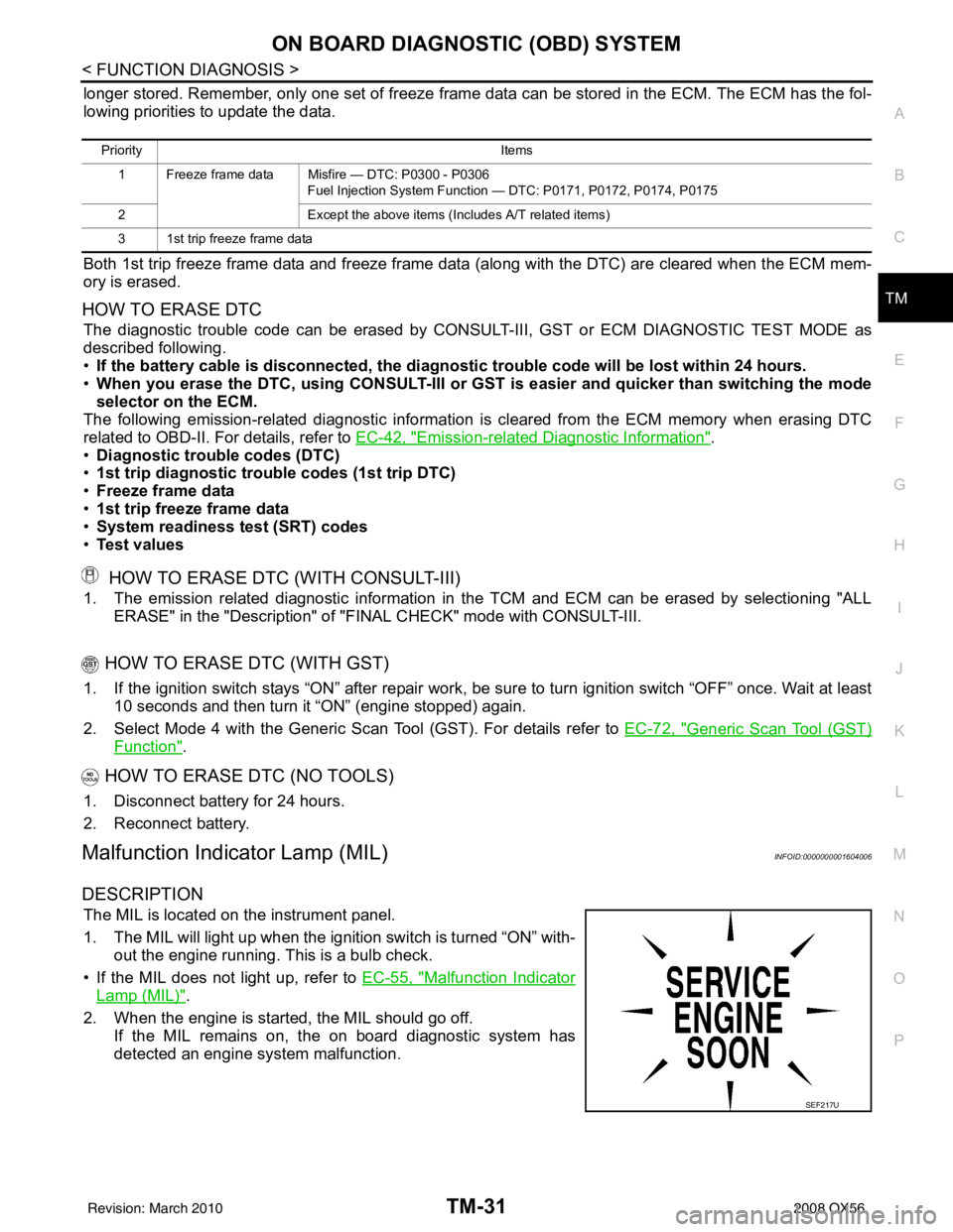
The MIL is located on the instrument panel.
1. The MIL will light up when the ignition switch is turned “ON” with-
out the engine running. This is a bulb check.
• If the MIL does not light up, refer to EC-55, "
Malfunction Indicator
Lamp (MIL)".
2. When the engine is start ed, the MIL should go off.
If the MIL remains on, the on board diagnostic system has
detected an engine system malfunction.
Priority Items
1 Freeze frame data Misfire — DTC: P0300 - P0306 Fuel Injection System Function — DTC: P0171, P0172, P0174, P0175
2 Except the above items (Includes A/T related items)
3 1st trip freeze frame data
SEF217U
Revision: March 2010 2008 QX56
Page 3581 of 4083

TM-34
< FUNCTION DIAGNOSIS >
DIAGNOSIS SYSTEM (TCM)
*1: Refer to EC-55, "Malfunction Indicator Lamp (MIL)".
*2:These malfunctions cannot be displayed MIL if another malfunction is assigned to MIL.
DATA MONITOR MODE
Display Items List
X: Standard, —: Not applicable
LC/B SOLENOID FNCT • TCM detects an improper voltage drop when it tries to
operate the solenoid valve.
• Condition of ATF pressure switch 2 is different from
monitor value, and relation between gear position and
actual gear ratio is irregular. P1774 P1774*2
TM-90
NO DTC IS DETECTED
FURTHER TESTING
MAY BE REQUIRED• No NG item has been detected.
XX
Items (CONSULT-III
screen terms) Malfunction is detected when... TCM self-di-
agnosis OBD-II (DTC)
Reference page
“TRANSMIS-
SION” with
CONSULT-III MIL indicator
lamp*1, “EN-
GINE” with
CONSULT-III or
GST
Monitored item (Unit) Monitor Item Selection
Remarks
ECU IN-
PUT SIG-
NALS MAIN SIG-
NALS SELEC-
TION
FROM
MENU
VHCL/S SE·A/T (km/h) XXX Output speed sensor
VHCL/S SE·MTR (km/h) X— X
ACCELE POSI (0.0/8) X— X Accelerator pedal position signal
THROTTLE POSI (0.0/8) XXXDegree of opening for accelerator recognized by
the TCM
For fail-safe operation, the specific value used
for control is displayed.
CLSD THL POS (ON-OFF display) X— X
Signal input with CAN communications
W/O THL POS (ON-OFF display) X— X
BRAKE SW (ON-OFF display) X— X Stop lamp switch
GEAR —XXGear position recognized by the TCM updated
after gear-shifting
ENGINE SPEED (rpm) XXX
INPUT SPEED (rpm) XXX
OUTPUT REV (rpm) XXX
GEAR RATIO —XX
TC SLIP SPEED (rpm) —XXDifference between engine speed and torque
converter input shaft speed
F SUN GR REV (rpm) —— X
F CARR GR REV (rpm) —— X
ATF TEMP SE 1 (V) X— X
ATF TEMP SE 2 (V) X— X
ATF TEMP 1 (° C) —XX
ATF TEMP 2 (° C) —XX
BATTERY VOLT (V) X— X
ATF PRES SW 1 (ON-OFF display) XXX Not mounted but displayed.
Revision: March 2010 2008 QX56
Page 3587 of 4083
TM-40
< COMPONENT DIAGNOSIS >
P0615 STARTER RELAY
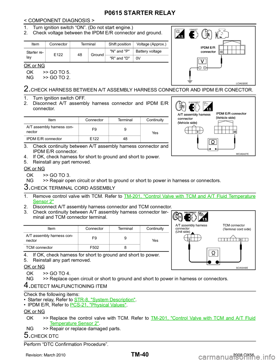
1. Turn ignition switch “ON”. (Do not start engine.)
2. Check voltage between the IPDM E/R connector and ground.
OK or NG
OK >> GO TO 5.
NG >> GO TO 2.
2.CHECK HARNESS BETWEEN A/T ASSEMBLY HARNESS CONNECTOR AND IPDM E/R CONECTOR.
1. Turn ignition switch OFF.
2. Disconnect A/T assembly harness connector and IPDM E/R connector.
3. Check continuity between A/T assembly harness connector and IPDM E/R connector.
4. If OK, check harness for short to ground and short to power.
5. Reinstall any part removed.
OK or NG
OK >> GO TO 3.
NG >> Repair open circuit or short to ground or short to power in harness or connectors.
3.CHECK TERMINAL CORD ASSEMBLY
1. Remove control valve with TCM. Refer to TM-201, "
Control Valve with TCM and A/T Fluid Temperature
Sensor 2"
2. Disconnect A/T assembly harness connector and TCM connector.
3. Check continuity between A/T assembly harness connector ter-
minal and TCM connector terminal.
4. If OK, check harness for short to ground and short to power.
5. Reinstall any part removed.
OK or NG
OK >> GO TO 4.
NG >> Replace open circuit or short to ground and short to power in harness or connectors.
4.DETECT MALFUNCTIONING ITEM
Check the following items:
• Starter relay, Refer to STR-8, "
System Description".
• IPDM E/R, Refer to PCS-21, "
Physical Values".
OK or NG
OK >> Replace the control valve with TCM. Refer to TM-201, "Control Valve with TCM and A/T Fluid
Temperature Sensor 2".
NG >> Repair or replace damaged parts.
5.CHECK DTC
Perform “DTC Confirmation Procedure”.
Item Connector Terminal Shift position Voltage (Approx.)
Starter re-
lay E122 48 Ground "N'' and "P'' Battery voltage
"R'' and "D'' 0V
LCIA0320E
Item Connector Terminal Continuity
A/T assembly harness con-
nector F9
9
Ye s
IPDM E/R connector E12248
WCIA0427E
Item Connector Terminal Continuity
A/T assembly harness con-
nector F9
9
Ye s
TCM connector F5028
SCIA5440E
Revision: March 2010 2008 QX56
Page 3639 of 4083
TM-92
< COMPONENT DIAGNOSIS >
MAIN POWER SUPPLY AND GROUND CIRCUIT
MAIN POWER SUPPLY AND GROUND CIRCUIT
Diagnosis ProcedureINFOID:0000000001604160
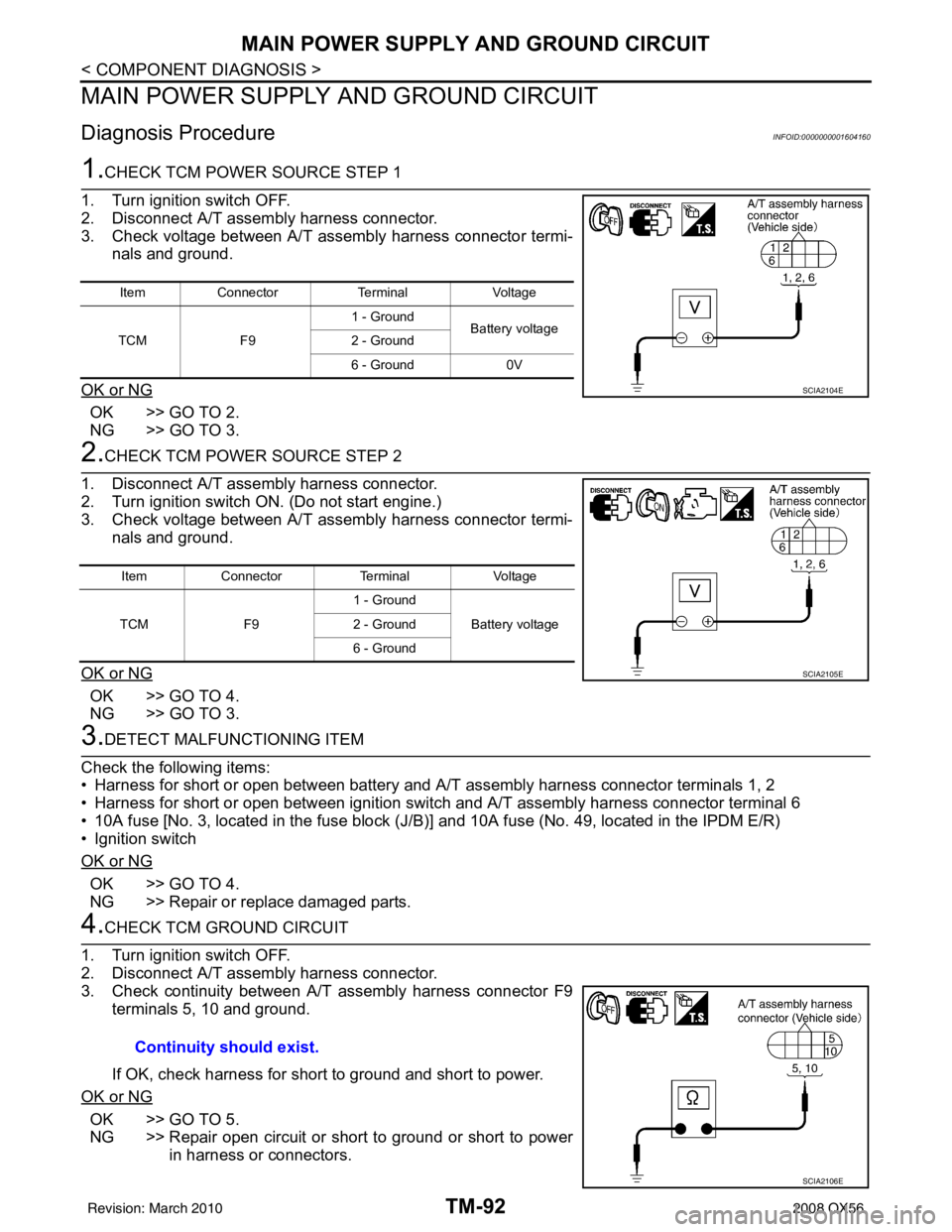
1.CHECK TCM POWER SOURCE STEP 1
1. Turn ignition switch OFF.
2. Disconnect A/T assembly harness connector.
3. Check voltage between A/T assembly harness connector termi- nals and ground.
OK or NG
OK >> GO TO 2.
NG >> GO TO 3.
2.CHECK TCM POWER SOURCE STEP 2
1. Disconnect A/T assembly harness connector.
2. Turn ignition switch ON. (Do not start engine.)
3. Check voltage between A/T assembly harness connector termi- nals and ground.
OK or NG
OK >> GO TO 4.
NG >> GO TO 3.
3.DETECT MALFUNCTIONING ITEM
Check the following items:
• Harness for short or open between battery and A/T assembly harness connector terminals 1, 2
• Harness for short or open between ignition switch and A/T assembly harness connector terminal 6
• 10A fuse [No. 3, located in the fuse block (J/B )] and 10A fuse (No. 49, located in the IPDM E/R)
• Ignition switch
OK or NG
OK >> GO TO 4.
NG >> Repair or replace damaged parts.
4.CHECK TCM GROUND CIRCUIT
1. Turn ignition switch OFF.
2. Disconnect A/T assembly harness connector.
3. Check continuity between A/T assembly harness connector F9 terminals 5, 10 and ground.
If OK, check harness for short to ground and short to power.
OK or NG
OK >> GO TO 5.
NG >> Repair open circuit or short to ground or short to power in harness or connectors.
Item Connector TerminalVoltage
TCM F91 - Ground
Battery voltage
2 - Ground
6 - Ground 0V
SCIA2104E
ItemConnector TerminalVoltage
TCM F91 - Ground
Battery voltage
2 - Ground
6 - Ground
SCIA2105E
Continuity should exist.
SCIA2106E
Revision: March 2010 2008 QX56
Page 3643 of 4083
TM-96
< COMPONENT DIAGNOSIS >
TOW MODE SWITCH
TOW MODE SWITCH
DescriptionINFOID:0000000001604165
When tow mode switch is “ON”, tow mode switch signals are sent to TCM from combination meter by CAN
communication line.Then it`s a tow mode condition.
Diagnosis ProcedureINFOID:0000000001604167
1.CHECK CAN COMMUNICATION LINE
Perform the self-diagnosis. Refer to TM-32, "
CONSULT-III Function (TRANSMISSION)".
Is any malfunction in the CAN communication indicated in the results?
YES >> Check CAN communication line. Refer to TM-38.
NO >> GO TO 2.
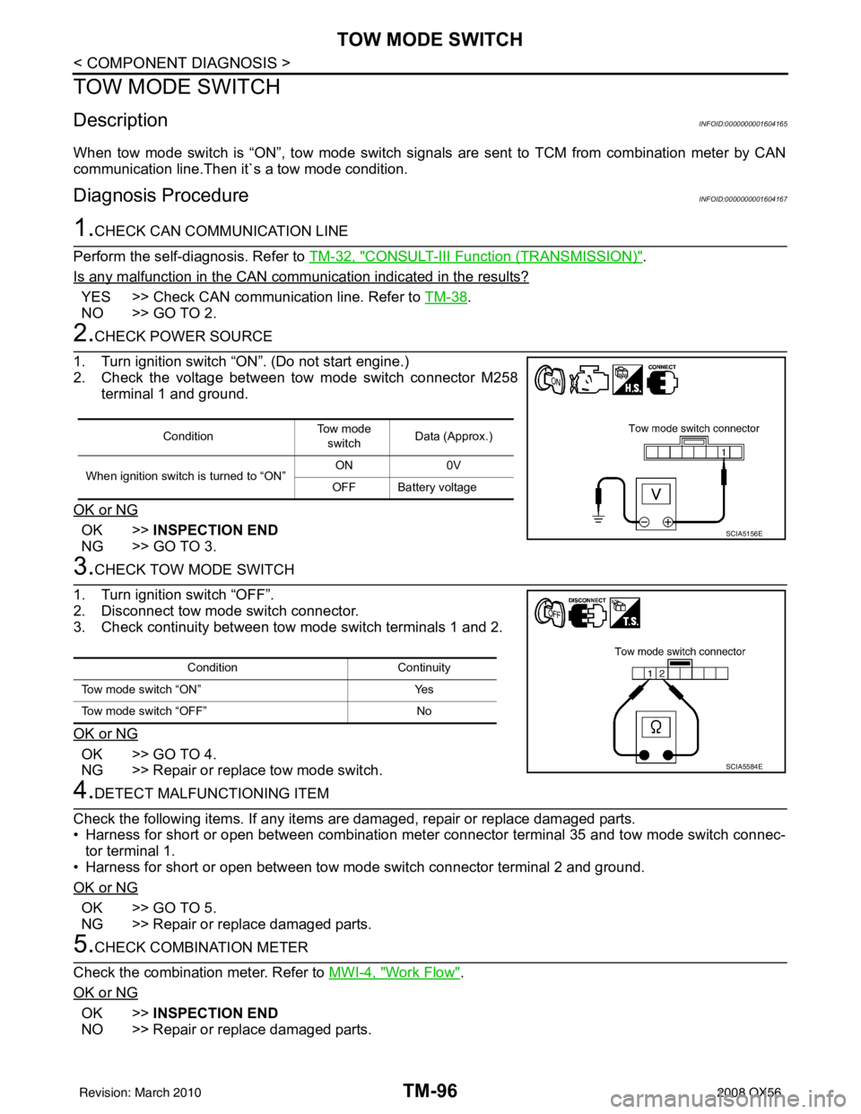
2.CHECK POWER SOURCE
1. Turn ignition switch “ON”. (Do not start engine.)
2. Check the voltage between tow mode switch connector M258 terminal 1 and ground.
OK or NG
OK >> INSPECTION END
NG >> GO TO 3.
3.CHECK TOW MODE SWITCH
1. Turn ignition switch “OFF”.
2. Disconnect tow mode switch connector.
3. Check continuity between tow mode switch terminals 1 and 2.
OK or NG
OK >> GO TO 4.
NG >> Repair or replace tow mode switch.
4.DETECT MALFUNCTIONING ITEM
Check the following items. If any items are damaged, repair or replace damaged parts.
• Harness for short or open between combination meter connector terminal 35 and tow mode switch connec- tor terminal 1.
• Harness for short or open between tow mode switch connector terminal 2 and ground.
OK or NG
OK >> GO TO 5.
NG >> Repair or replace damaged parts.
5.CHECK COMBINATION METER
Check the combination meter. Refer to MWI-4, "
Work Flow".
OK or NG
OK >> INSPECTION END
NO >> Repair or replace damaged parts.
Condition To w m o d e
switch Data (Approx.)
When ignition switch is turned to “ON” ON
0V
OFF Battery voltage
SCIA5156E
Condition Continuity
Tow mode switch “ON” Yes
Tow mode switch “OFF” No
SCIA5584E
Revision: March 2010 2008 QX56
Page 3647 of 4083
TM-100
< COMPONENT DIAGNOSIS >
A/T SHIFT LOCK SYSTEM
Terminals And Reference Values
INFOID:0000000001604171
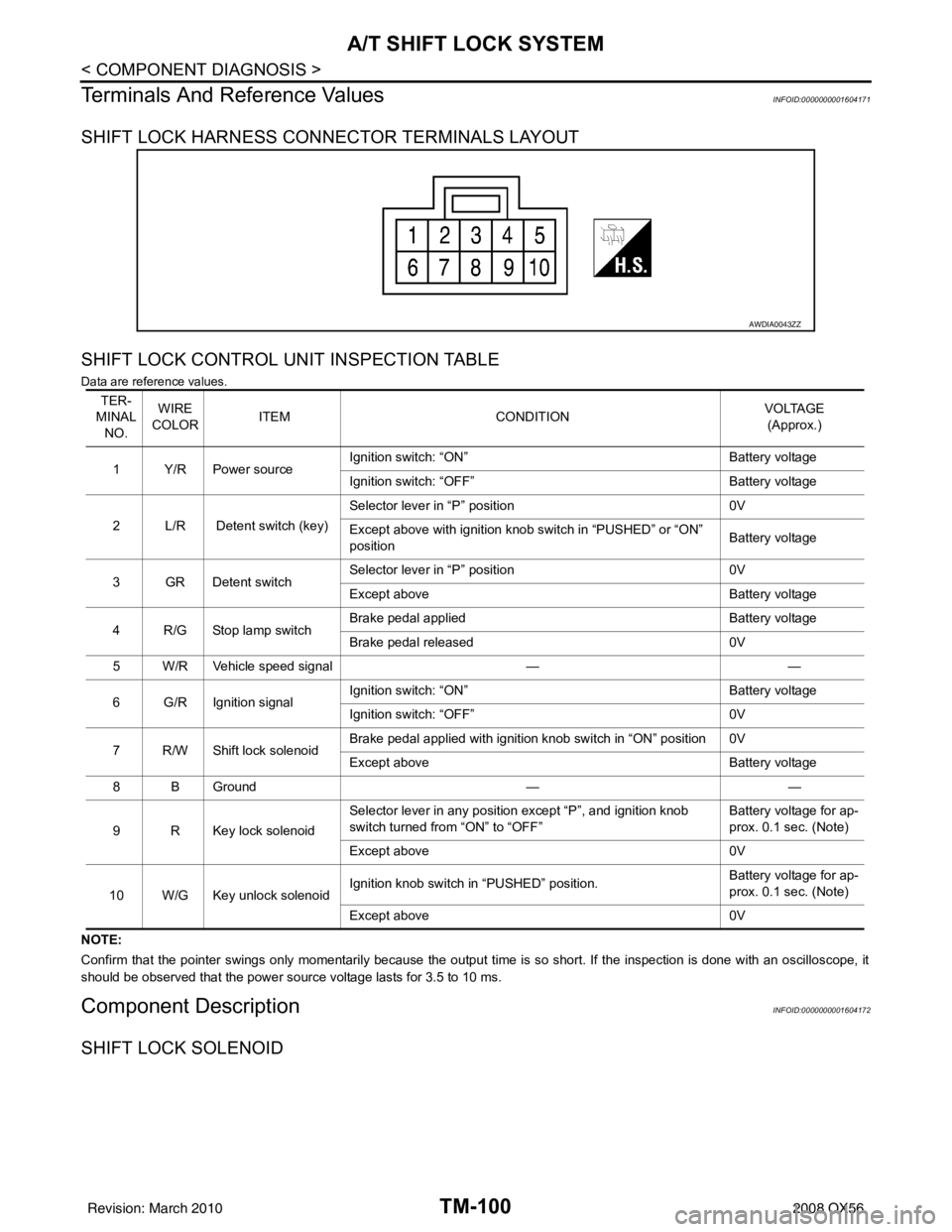
SHIFT LOCK HARNESS CONNECTOR TERMINALS LAYOUT
SHIFT LOCK CONTROL UNIT INSPECTION TABLE
Data are reference values.
NOTE:
Confirm that the pointer swings only momentarily because the output time is so short. If the inspection is done with an oscillo scope, it
should be observed that the power source voltage lasts for 3.5 to 10 ms.
Component DescriptionINFOID:0000000001604172
SHIFT LOCK SOLENOID
AWDIA0043ZZ
TER-
MINAL NO. WIRE
COLOR ITEM
CONDITION VOLTAGE
(Approx.)
1Y/RPower source Ignition switch: “ON”
Battery voltage
Ignition switch: “OFF” Battery voltage
2 L/R Detent switch (key) Selector lever in “P” position
0V
Except above with ignition knob switch in “PUSHED” or “ON”
position Battery voltage
3GRDetent switch Selector lever in “P” position
0V
Except above Battery voltage
4 R/G Stop lamp switch Brake pedal applied
Battery voltage
Brake pedal released 0V
5 W/R Vehicle speed signal ——
6 G/R Ignition signal Ignition switch: “ON”
Battery voltage
Ignition switch: “OFF” 0V
7 R/W Shift lock solenoid Brake pedal applied with ignition knob switch in “ON” position 0V
Except above
Battery voltage
8 B Ground ——
9 R Key lock solenoid Selector lever in any position except “P”, and ignition knob
switch turned from “ON” to “OFF”
Battery voltage for ap-
prox. 0.1 sec. (Note)
Except above 0V
10 W/G Key unlock solenoid Ignition knob switch in “PUSHED” position.
Battery voltage for ap-
prox. 0.1 sec. (Note)
Except above 0V
Revision: March 2010 2008 QX56
Page 3648 of 4083
A/T SHIFT LOCK SYSTEMTM-101
< COMPONENT DIAGNOSIS >
CEF
G H
I
J
K L
M A
B
TM
N
O P
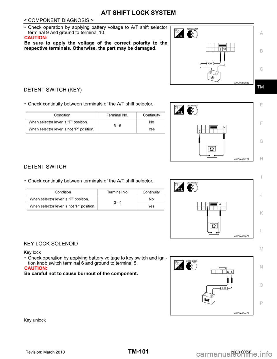
• Check operation by applying battery voltage to A/T shift selector terminal 9 and ground to terminal 10.
CAUTION:
Be sure to apply the voltage of the correct polarity to the
respective terminals. Otherwise, the part may be damaged.
DETENT SWITCH (KEY)
• Check continuity between terminals of the A/T shift selector.
DETENT SWITCH
• Check continuity between terminals of the A/T shift selector.
KEY LOCK SOLENOID
Key lock
• Check operation by applying battery voltage to key switch and igni-
tion knob switch terminal 6 and ground to terminal 5.
CAUTION:
Be careful not to cause burnout of the component.
Key unlock
AWDIA0700ZZ
Condition Terminal No. Continuity
When selector lever is “P” position. 5 - 6No
When selector lever is not “P” position. Yes
AWDIA0567ZZ
ConditionTerminal No. Continuity
When selector lever is “P” position. 3 - 4No
When selector lever is not “P” position. Yes
AWDIA0568ZZ
AWDIA0544ZZ
Revision: March 2010 2008 QX56
Page 3649 of 4083
TM-102
< COMPONENT DIAGNOSIS >
A/T SHIFT LOCK SYSTEM
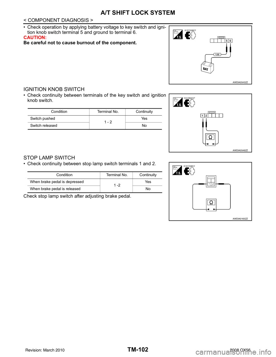
• Check operation by applying battery voltage to key switch and igni-tion knob switch terminal 5 and ground to terminal 6.
CAUTION:
Be careful not to cause burnout of the component.
IGNITION KNOB SWITCH
• Check continuity between terminals of the key switch and ignition
knob switch.
STOP LAMP SWITCH
• Check continuity between stop lamp switch terminals 1 and 2.
Check stop lamp switch after adjusting brake pedal.
AWDIA0545ZZ
Condition Terminal No. Continuity
Switch pushed 1 - 2Ye s
Switch released No
AWDIA0546ZZ
ConditionTerminal No. Continuity
When brake pedal is depressed 1 -2Ye s
When brake pedal is released No
AWDIA0165ZZ
Revision: March 2010 2008 QX56