2008 INFINITI QX56 radiator
[x] Cancel search: radiatorPage 2605 of 4083
GENERAL MAINTENANCEMA-7
< ON-VEHICLE MAINTENANCE >
C
DE
F
G H
I
J
K L
M B
MA
N
O A
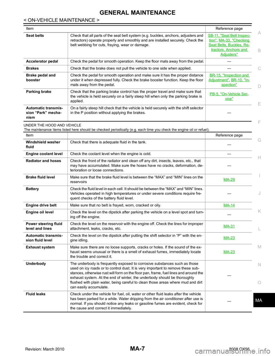
UNDER THE HOOD AND VEHICLE
The maintenance items listed here should be checked periodically (e.g. each time you check the engine oil or refuel).
Seat beltsCheck that all parts of the seat belt system (e.g. buckles, anchors, adjusters and
retractors) operate properly and smoothly and are installed securely. Check the
belt webbing for cuts, fraying, wear or damage. SB-11, "Seat Belt Inspec-
tion", MA-33, "Checking
Seat Belts, Buckles, Re-
tractors, Anchors and
Adjusters"
Accelerator pedal
Check the pedal for smooth operation. Keep the floor mats away from the pedal. —
Brakes Check that the brake does not pull the vehicle to one side when applied. —
Brake pedal and
booster Check the pedal for smooth operation and make sure it has the proper distance
under it when depressed fully. Check the brake booster function. Keep the floor
mats away from the pedal. BR-15, "
Inspection and
Adjustment", BR-10, "In-
spection"
Parking brake
Check that the parking brake control has the proper travel and make sure that
the vehicle is held securely on a fairly steep hill when only the parking brake is
applied. PB-5, "On-Vehicle Ser-
vice"
Automatic transmis-
sion “Park” mecha-
nismOn a fairly steep hill check that the vehicle is held securely with the shift selector
in the P position without applying the brakes.
—
Item
Reference page
Item Reference page
Windshield washer
fluid Check that there is adequate fluid in the tank.
—
Engine coolant level Check the coolant level when the engine is cold. —
Radiator and hoses Check the front of the radiator and clean off any dirt, insects, leaves, etc., that
may have accumulated. Make sure the hoses have no cracks, deformation, de-
terioration or loose connections. —
Brake fluid level Make sure that the brake fluid level is between the “MAX” and “MIN” lines on the
reservoirs MA-29
Battery
Check the fluid level in each cell. It should be between the “MAX” and “MIN” lines.
Vehicles operated in high temperatures or under severe conditions require fre-
quent checks of the battery fluid level. —
Engine drive belt Make sure that no belt is frayed, worn, cracked or oily. MA-14
Engine oil levelCheck the level on the dipstick after parking the vehicle on a level spot and turn-
ing off the engine. —
Power steering fluid
level and lines Check the level on the reservoir with the engine off. Check the lines for improper
attachment, leaks, cracks, etc.
MA-31
Automatic transmis-
sion fluid levelCheck the level on the dipstick after putting the shift selector in “P” with the en-
gine idling.
MA-23
Exhaust system
Make sure there are no loose supports, cracks or holes. If the sound of the ex-
haust seems unusual or there is a smell of exhaust fumes, immediately locate
the trouble and correct it. MA-23
Underbody
The underbody is frequently exposed to corrosive substances such as those
used on icy roads or to control dust. It is very important to remove these sub-
stances, otherwise rust will form on the floor pan, frame, fuel lines and around the
exhaust system. At the end of winter, the underbody should be thoroughly
flushed with plain water, being careful to clean those areas where mud and dirt
can easily accumulate. —
Fluid leaks Check under the vehicle for fuel, oil, water or other fluid leaks after the vehicle
has been parked for a while. Water dripping from the air conditioner after use is
normal. If you should notice any leaks or gasoline fumes are evident, check for
the cause and correct it immediately. —
Revision: March 2010
2008 QX56
Page 2613 of 4083

ENGINE MAINTENANCEMA-15
< ON-VEHICLE MAINTENANCE >
C
DE
F
G H
I
J
K L
M B
MA
N
O A
3. Open the radiator drain plug at the bottom of the radiator, and
remove the radiator filler cap. This is the only step required
when partially draining the cooling system (radiator only).
CAUTION:
Do not to allow the coolant to contact the drive belts.
4. When draining all of the coolant in the system for engine removal or repair, it is necessary to drain the cylinder block.
Remove the RH cylinder block drain plug to drain the right bank
and the oil cooler hose to drain the left bank as shown.
5. Remove the reservoir tank to drain the engine cool ant, then clean the reservoir tank before installing it.
6. Check the drained coolant for contaminants such as rust, corrosion or discoloration. If the coolant is contaminated, flush the engine cooling system. Refer to CO-11, "
Changing Engine Cool-
ant" .
REFILLING ENGINE COOLANT
1. Close the radiator drain plug. Install the reservoir tank, cylinder block drain plug, and the oil cooler hose, if
removed for a total system drain or for engine removal or repair.
• The radiator must be complete ly empty of coolant and water.
• Apply sealant to the threads of the cylinder block drain plug. Use Genuine High Performance Thread
Sealant or equivalent. Refer to GI-15, "
Recommended Chemical Products and Sealants" .
2. Set the vehicle heater controls to the full HOT and heat er ON position. Turn the vehicle ignition ON with
the engine OFF as necessary to activate the heater mode.
3. Remove the vented reservoir cap and replace it wit h a non-vented reservoir cap before filling the cooling
system.
WBIA0391E
PBIC0146E
WBIA0392E
Radiator drain plug : Refer to CO-15 .
RH cylinder block drain plug : Refer to EM-82
.
Revision: March 2010 2008 QX56
Page 2614 of 4083
MA-16
< ON-VEHICLE MAINTENANCE >
ENGINE MAINTENANCE
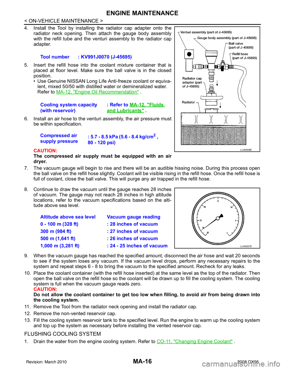
4. Install the Tool by installing the radiator cap adapter onto theradiator neck opening. Then attach the gauge body assembly
with the refill tube and the venturi assembly to the radiator cap
adapter.
5. Insert the refill hose into the coolant mixture container that is placed at floor level. Make sure the ball valve is in the closed
position.
• Use Genuine NISSAN Long Life Anti-freeze coolant or equiva-
lent, mixed 50/50 with distilled water or demineralized water.
Refer to MA-12, "
Engine Oil Recommendation" .
6. Install an air hose to the venturi assembly, the air pressure must be within specification.
CAUTION:
The compressed air supply must be equipped with an air
dryer.
7. The vacuum gauge will begin to rise and there will be an audible hissing noise. During this process open the ball valve on the refill hose slightly. Coolant will be vi sible rising in the refill hose. Once the refill hose is
full of coolant, close the ball valve. This will purge any air trapped in the refill hose.
8. Continue to draw the vacuum until the gauge reaches 28 inches of vacuum. The gauge may not reach 28 inches in high altitude
locations, refer to the vacuum specifications based on the alti-
tude above sea level.
9. When the vacuum gauge has reached the specifi ed amount, disconnect the air hose and wait 20 seconds
to see if the system loses any vacuum. If the vacuum level drops, perform any necessary repairs to the
system and repeat steps 6 - 8 to bring the vacuum to the specified amount. Recheck for any leaks.
10. Place the coolant container (with the refill hose insert ed) at the same level as the top of the radiator. Then
open the ball valve on the refill hose so the coolant will be drawn up to fill the cooling system. The cooling
system is full when the vacuum gauge reads zero.
CAUTION:
Do not allow the coolant container to get too low when filling, to avoid air from being drawn into
the cooling system.
11. Remove the Tool from the radiator neck opening and install the radiator cap.
12. Remove the non-vented reservoir cap.
13. Fill the cooling system reservoir tank to the specif ied level. Run the engine to warm up the cooling system
and top up the system as necessary before installing the vented reservoir cap.
FLUSHING COOLING SYSTEM
1. Drain the water from the engine cooling system. Refer to CO-11, "Changing Engine Coolant" .
Tool number : KV991J0070 (J-45695)
Cooling system capacity
(with reservoir)
: Refer to
MA-12, "
Fluids
and Lubricants" .
Compressed air
supply pressure : 5.7 - 8.5 kPa (5.6 - 8.4 kg/cm
2 ,
80 - 120 psi)
LLIA0058E
Altitude above sea level Vacuum gauge reading
0 - 100 m (328 ft) : 28 inches of vacuum
300 m (984 ft) : 27 inches of vacuum
500 m (1,641 ft) : 26 inches of vacuum
1,000 m (3,281 ft) : 24 - 25 inches of vacuum
LLIA0057E
Revision: March 2010 2008 QX56
Page 2615 of 4083
ENGINE MAINTENANCEMA-17
< ON-VEHICLE MAINTENANCE >
C
DE
F
G H
I
J
K L
M B
MA
N
O A
2. Fill the radiator and the reservoir tank (to the “MAX”
line), with water. Reinstall the radiator cap and leave
the vented reservoir cap off.
3. Run the engine until it reaches normal operating temperature.
4. Press the engine accelerator two or three times under no-load.
5. Stop the engine and wait until it cools down.
6. Drain the water from the engine cooling system. Refer to CO-11, "
Changing Engine Coolant" .
7. Repeat steps 2 through 6 until clear water begins to drain from the radiator.
Checking Fuel LineINFOID:0000000001606172
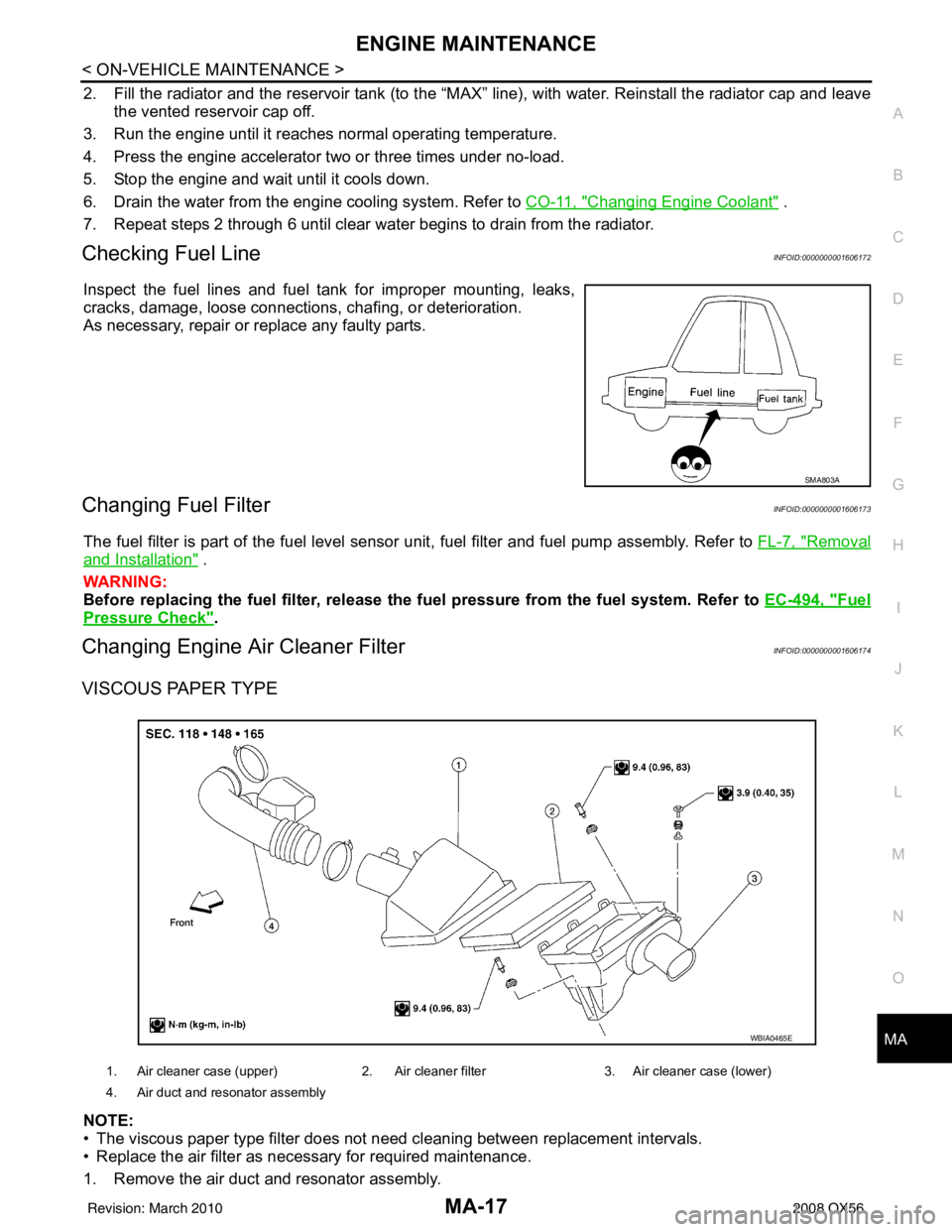
Inspect the fuel lines and fuel tank for improper mounting, leaks,
cracks, damage, loose connections, chafing, or deterioration.
As necessary, repair or replace any faulty parts.
Changing Fuel FilterINFOID:0000000001606173
The fuel filter is part of the fuel level sensor unit, fuel filter and fuel pump assembly. Refer to FL-7, "Removal
and Installation" .
WARNING:
Before replacing the fuel filter, release the fuel pressure from the fuel system. Refer to EC-494, "
Fuel
Pressure Check".
Changing Engine Air Cleaner FilterINFOID:0000000001606174
VISCOUS PAPER TYPE
NOTE:
• The viscous paper type filter does not need cleaning between replacement intervals.
• Replace the air filter as necessary for required maintenance.
1. Remove the air duct and resonator assembly.
SMA803A
1. Air cleaner case (upper) 2. Air cleaner filter3. Air cleaner case (lower)
4. Air duct and resonator assembly
WBIA0465E
Revision: March 2010 2008 QX56
Page 2622 of 4083
MA-24
< ON-VEHICLE MAINTENANCE >
CHASSIS AND BODY MAINTENANCE
5. Drive the vehicle to increase the ATF temperature to 80° C (176 ° F).
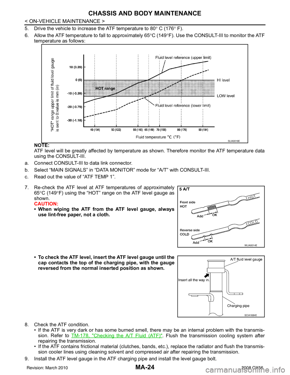
6. Allow the ATF temperature to fall to approximately 65 °C (149° F). Use the CONSULT-III to monitor the ATF
temperature as follows:
NOTE:
ATF level will be greatly affected by temperature as shown. Therefore monitor the ATF temperature data
using the CONSULT-III.
a. Connect CONSULT-III to data link connector.
b. Select “MAIN SIGNALS” in “DATA MONI TOR” mode for “A/T” with CONSULT-III.
c. Read out the value of “ATF TEMP 1”.
7. Re-check the ATF level at ATF temperatures of approximately 65°C (149° F) using the “HOT” range on the ATF level gauge as
shown.
CAUTION:
• When wiping the ATF from the ATF level gauge, always use lint-free paper, not a cloth.
• To check the ATF level, insert the ATF level gauge until the cap contacts the top of the ch arging pipe, with the gauge
reversed from the normal inserted position as shown.
8. Check the ATF condition. • If the ATF is very dark or has some burned smell, there may be an internal problem with the transmis-
sion. Refer to TM-178, "
Checking the A/T Fluid (ATF)". Flush the transmission cooling system after
repairing the transmission.
• If the ATF contains frictional material (clutches, bands , etc.), replace the radiator and flush the transmis-
sion cooler lines using cleaning solvent and compressed air after repairing the transmission.
9. Install the ATF level gauge in the ATF charging pipe and install the level gauge bolt.
SLIA0016E
WLIA0014E
SCIA1684E
Revision: March 2010 2008 QX56
Page 3027 of 4083

SQUEAK AND RATTLE TROUBLE DIAGNOSESRF-43
< SYMPTOM DIAGNOSIS >
C
DE
F
G H
I
J
L
M A
B
RF
N
O P
Most of these incidents can be repaired by adjusting, se curing or insulating the item(s) or component(s) caus-
ing the noise.
SUNROOF/HEADLINING
Noises in the sunroof/headlining area can often be traced to one of the following:
1. Sunroof lid, rail, linkage or seals making a rattle or light knocking noise
2. Sunvisor shaft shaking in the holder
3. Front or rear windshield touching headlining and squeaking
Again, pressing on the components to stop the noise while duplicating the conditions can isolate most of these
incidents. Repairs usually consist of insulating with felt cloth tape.
SEATS
When isolating seat noise it's important to note the position the seat is in and the load placed on the seat when
the noise is present. These conditions should be duplicated when verifying and isolating the cause of the
noise.
Cause of seat noise include:
1. Headrest rods and holder
2. A squeak between the seat pad cushion and frame
3. The rear seatback lock and bracket
These noises can be isolated by moving or pressing on the suspected components while duplicating the con-
ditions under which the noise occurs. Most of thes e incidents can be repaired by repositioning the component
or applying urethane tape to the contact area.
UNDERHOOD
Some interior noise may be caused by components under the hood or on the engine wall. The noise is then
transmitted into the passenger compartment.
Causes of transmitted underhood noise include:
1. Any component mounted to the engine wall
2. Components that pass through the engine wall
3. Engine wall mounts and connectors
4. Loose radiator mounting pins
5. Hood bumpers out of adjustment
6. Hood striker out of adjustment
These noises can be difficult to isolate since they cannot be reached from the interior of the vehicle. The best
method is to secure, move or insulate one component at a time and test drive the vehicle. Also, engine RPM
or load can be changed to isolate the noise. Repairs can usually be made by moving, adjusting, securing, or
insulating the component causing the noise.
Revision: March 2010 2008 QX56
Page 3162 of 4083

SE-40
< SYMPTOM DIAGNOSIS >
SQUEAK AND RATTLE TROUBLE DIAGNOSES
Most of these incidents can be repaired by adjusting, securing or insulating the item(s) or component(s) caus-
ing the noise.
SUNROOF/HEADLINING
Noises in the sunroof/headlining area c an often be traced to one of the following:
1. Sunroof lid, rail, linkage or seals making a rattle or light knocking noise
2. Sun visor shaft shaking in the holder
3. Front or rear windshield touching headliner and squeaking
Again, pressing on the components to stop the noise while duplicating the conditions can isolate most of these
incidents. Repairs usually consist of insulating with felt cloth tape.
OVERHEAD CONSOLE (FRONT AND REAR)
Overhead console noises are often caused by the c onsole panel clips not being engaged correctly. Most of
these incidents are repaired by pushing up on the c onsole at the clip locations until the clips engage.
In addition look for:
1. Loose harness or harness connectors.
2. Front console map/reading lamp lense loose.
3. Loose screws at console attachment points.
SEATS
When isolating seat noise it's important to note the pos ition the seat is in and the load placed on the seat when
the noise is present. These conditions should be duplicated when verifying and isolating the cause of the
noise.
Cause of seat noise include:
1. Headrest rods and holder
2. A squeak between the seat pad cushion and frame
3. The rear seatback lock and bracket
These noises can be isolated by moving or pressing on the suspected components while duplicating the con-
ditions under which the noise occurs. Most of thes e incidents can be repaired by repositioning the component
or applying urethane tape to the contact area.
UNDERHOOD
Some interior noise may be caused by components under the hood or on the engine wall. The noise is then
transmitted into the passenger compartment.
Causes of transmitted underhood noise include:
1. Any component mounted to the engine wall
2. Components that pass through the engine wall
3. Engine wall mounts and connectors
4. Loose radiator mounting pins
5. Hood bumpers out of adjustment
6. Hood striker out of adjustment
These noises can be difficult to isolate since they cannot be reached from the interior of the vehicle. The best
method is to secure, move or insulate one component at a time and test drive the \
vehicle. Also, engine RPM
or load can be changed to isolate the noise. Repairs can usually be made by moving, adjusting, securing, or
insulating the component causing the noise.
Revision: March 2010 2008 QX56
Page 3722 of 4083
PRECAUTIONSTM-175
< PRECAUTION >
CEF
G H
I
J
K L
M A
B
TM
N
O P
• All parts should be carefully cleaned with a general purpose, non-flammable solvent before inspection or reassembly.
• Gaskets, seals and O-rings should be replaced any time the transmission is disassembled.
• It is very important to perform func tional tests whenever they are indicated.
• The valve body contains precision parts and requires extreme care when parts are removed and serviced. Place disassembled valve body parts in order for easier and proper assembly. Care will also prevent springs
and small parts from becoming scattered or lost.
• Properly installed valves, sleeves, plugs, etc. will slide along bores in valve body under their own weight.
• Before assembly, apply a coat of recommended ATF to all parts. Apply petroleum jelly to protect O-rings and
seals, or hold bearings and washers in pl ace during assembly. Do not use grease.
• Extreme care should be taken to avoid damage to O-rings, seals and gaskets when assembling.
• Clean or replace ATF cooler if excessive foreign material is found in oil pan or clogging strainer. Refer to TM-
182, "A/T Fluid Cooler Cleaning".
• After overhaul, refill the transmission with new ATF.
• When the A/T drain plug is removed, only some of the fluid is drained. Old A/T fluid will remain in torque con- verter and ATF cooling system.
Always follow the procedures under “Changing A/T Fluid” in the AT section when changing A/T fluid. Refer to
TM-180, "
Changing the A/T Fluid (ATF)".
Service Notice or PrecautionINFOID:0000000001531487
ATF COOLER SERVICE
• If A/T fluid contains fictional material (clutches, bands, etc.), or if an A/T is repaired, overhauled, or replaced,
inspect and clean the A/T fluid cooler mounted in the radiat or or replace the radiator. Flush cooler lines with
cleaning solvent and compressed air after repair. For A/T fluid cooler cleaning procedure, refer to TM-182,
"A/T Fluid Cooler Cleaning". For radiator replacement, refer to CO-15, "Removal and Installation".
CHECKING AND CHANGING A/T FLUID
• Increase ATF oil temperature to 80 °C (176° F) first, then check and adjust oil level at 65 °C (149° F).
NOTE:
The A/T has both water cooling and air cooling systems. The air cooling system has a bypass valve. When
ATF oil temperature is at or below 50 °C (122° F), it does not flow through the air cooled system. If A/T oil
level is adjusted without flow throughout the entir e system, the level will be 10mm lower than required.
Therefore, all piping should be filled with oil when adjusting level.
OBD-II SELF-DIAGNOSIS
• A/T self-diagnosis is performed by the TCM in combination with the ECM. Refer to the table on TM-32,
"CONSULT-III Function (TRANSMISSION)" for the indicator used to display each self-diagnostic result.
• The self-diagnostic results indicated by the MIL are automatically stored in both the ECM and TCM memo- ries.
Always perform the procedure on TM-30, "
OBD-II Diagnostic Trouble Code (DTC)" to complete the
repair and avoid unnecessary blinking of the MIL.
For details of OBD-II, refer to TM-30
.
• Certain systems and components, especially those related to OBD, may use the new style slide-
locking type harness connector. For descrip tion and how to disconnect, refer to PG-65
.
Revision: March 2010 2008 QX56