2008 INFINITI QX56 radiator
[x] Cancel search: radiatorPage 1607 of 4083
![INFINITI QX56 2008 Factory Service Manual EC-308
< COMPONENT DIAGNOSIS >[VK56DE]
P1217 ENGINE OVER TEMPERATURE
4. Make sure that cooling fan operates.
OK or NG
OK >> GO TO 4.
NG >> Check cooling fan control circuit. (Go to "PROCEDURE
A".)
4.C INFINITI QX56 2008 Factory Service Manual EC-308
< COMPONENT DIAGNOSIS >[VK56DE]
P1217 ENGINE OVER TEMPERATURE
4. Make sure that cooling fan operates.
OK or NG
OK >> GO TO 4.
NG >> Check cooling fan control circuit. (Go to "PROCEDURE
A".)
4.C](/manual-img/42/57030/w960_57030-1606.png)
EC-308
< COMPONENT DIAGNOSIS >[VK56DE]
P1217 ENGINE OVER TEMPERATURE
4. Make sure that cooling fan operates.
OK or NG
OK >> GO TO 4.
NG >> Check cooling fan control circuit. (Go to "PROCEDURE
A".)
4.CHECK COOLING SYSTEM FOR LEAK
Refer to CO-10, "
Inspection".
OK or NG
OK >> GO TO 5.
NG >> Check the following for leak. •Hose
• Radiator
• Radiator cap
• Water pump
• Reservoir tank
5.CHECK COMPONENT PARTS
Check the following.
• RESERVOIR TANK CAP (Refer to CO-10, "
Inspection".)
• Thermostat. (Refer to CO-22, "
Removal and Installation".)
• Engine coolant temperature sensor. (Refer to EC-126, "
Component Inspection".)
OK or NG
OK >> GO TO 6.
NG >> Replace malfunctioning component.
6.CHECK MAIN 13 CAUSES
If the cause cannot be isolated, go to EC-308, "
Main 13 Causes of Overheating".
>> INSPECTION END
Main 13 Causes of OverheatingINFOID:0000000001351718
SEF882V
Engine Step Inspection item EquipmentStandardReference page
OFF 1 • Blocked radiator • Blocked condenser
• Blocked radiator grille
• Blocked bumper • Visual
No blocking —
2 • Coolant mixture • Coolant tester 50 - 50% coolant mixtureCO-10
3 • Coolant level • VisualCoolant up to MAX level in
reservoir tank and radiator
filler neck CO-11, "Changing Engine
Coolant"
4 • Reservoir tank cap • Pre
ssure tester 95 - 125 kPa
(0.97 - 1.28 kg/cm2, 14 -
18 psi) (Limit) CO-10, "
Inspection"
ON*25 • Coolant leaks
• VisualNo leaks CO-10, "Inspection"
ON*26 • Thermostat • Touch the upper and
lower radiator hoses Both hoses should be hot
CO-22, "Removal and In-
stallation"
ON*17 • Cooling fan • CONSULT-IIIOperating See trouble diagnosis for
DTC P1217 ( EC-36
).
Revision: March 2010 2008 QX56
Page 1608 of 4083
![INFINITI QX56 2008 Factory Service Manual P1217 ENGINE OVER TEMPERATUREEC-309
< COMPONENT DIAGNOSIS > [VK56DE]
C
D
E
F
G H
I
J
K L
M A
EC
NP
O
*1: Turn the ignition switch ON.
*2: Engine running at 3,000 rpm for 10 minutes.
*3: Drive at 90 km INFINITI QX56 2008 Factory Service Manual P1217 ENGINE OVER TEMPERATUREEC-309
< COMPONENT DIAGNOSIS > [VK56DE]
C
D
E
F
G H
I
J
K L
M A
EC
NP
O
*1: Turn the ignition switch ON.
*2: Engine running at 3,000 rpm for 10 minutes.
*3: Drive at 90 km](/manual-img/42/57030/w960_57030-1607.png)
P1217 ENGINE OVER TEMPERATUREEC-309
< COMPONENT DIAGNOSIS > [VK56DE]
C
D
E
F
G H
I
J
K L
M A
EC
NP
O
*1: Turn the ignition switch ON.
*2: Engine running at 3,000 rpm for 10 minutes.
*3: Drive at 90 km/h (55 MPH) for 30 minutes and then let idle for 10 minutes.
*4: After 60 minutes of cool down time.
For more information, refer to
CO-8, "
Troubleshooting Chart".
OFF 8 • Combustion gas leak • Color checker chemical
tester 4 Gas analyzerNegative
—
ON*
39 • Coolant temperature gauge • Visual Gauge less than 3/4 when
driving —
• Coolant overflow to res- ervoir tank • Visual
No overflow during driving
and idling CO-11, "
Changing Engine
Coolant"
OFF*410 • Coolant return from res-
ervoir tank to radiator • Visual Should be initial level in
reservoir tank CO-11, "Changing Engine
Coolant"
OFF 12 • Cylinder head
• Straight gauge feeler
gauge 0.1 mm (0.004 in) Maxi-
mum distortion (warping) EM-72, "Inspection After
Disassembly"
13 • Cylinder block and pis-
tons • Visual No scuffing on cylinder
walls or piston EM-90, "Inspection After
Disassembly"
Engine Step Inspection item
EquipmentStandardReference page
Revision: March 2010 2008 QX56
Page 1783 of 4083
![INFINITI QX56 2008 Factory Service Manual EC-484
< SYMPTOM DIAGNOSIS >[VK56DE]
ENGINE CONTROL SYSTEM SYMPTOMS
1 - 6: The numbers refer to the order of inspection.Exhaust Exhaust manifold/Tube/Muffler/
Gasket 55555 55 5EM-30
,
EX-
5Three way INFINITI QX56 2008 Factory Service Manual EC-484
< SYMPTOM DIAGNOSIS >[VK56DE]
ENGINE CONTROL SYSTEM SYMPTOMS
1 - 6: The numbers refer to the order of inspection.Exhaust Exhaust manifold/Tube/Muffler/
Gasket 55555 55 5EM-30
,
EX-
5Three way](/manual-img/42/57030/w960_57030-1782.png)
EC-484
< SYMPTOM DIAGNOSIS >[VK56DE]
ENGINE CONTROL SYSTEM SYMPTOMS
1 - 6: The numbers refer to the order of inspection.Exhaust Exhaust manifold/Tube/Muffler/
Gasket 55555 55 5EM-30
,
EX-
5Three way catalyst
Lubrica-
tion Oil pan/Oil strainer/Oil pump/Oil
filter/Oil gallery/Oil cooler
55555 55 5EM-33
,
LU-
14 , LU-11 ,
LU-12
Oil level (Low)/Filthy oil LU-8, "In-
spection"
Cooling Radiator/Hose/Radiator filler cap
55555 55 45 CO-15
Thermostat
5CO-22
Water pump CO-20
Water galleryCO-6
Cooling fan5CO-18,
CO-
19
Coolant level (Low)/Contaminat-
ed coolant 5
CO-10
IVIS (INFINITI Vehicle Immobilizer System —
NATS) 11
SEC-8
SYMPTOM
Reference
page
HARD/NO START/RESTART (EXCP. HA)
ENGINE STALL
HESITATION/SURGING/FLAT SPOT
SPARK KNOCK/DETONATION
LACK OF POWER/POOR ACCELERATION
HIGH IDLE/LOW IDLE
ROUGH IDLE/HUNTING
IDLING VIBRATION
SLOW/NO RETURN TO IDLE
OVERHEATS/WATER TEMPERATURE HIGH
EXCESSIVE FUEL CONSUMPTION
EXCESSIVE OIL CONSUMPTION
BATTERY DEAD (UNDER CHARGE)
Warranty symptom code AA AB AC AD AE AF AG AH AJ AK AL AM HA
Revision: March 2010 2008 QX56
Page 1790 of 4083
![INFINITI QX56 2008 Factory Service Manual PREPARATIONEC-491
< PREPARATION > [VK56DE]
C
D
E
F
G H
I
J
K L
M A
EC
NP
O
PREPARATION
PREPARATION
Special Service ToolINFOID:0000000001351224
The actual shapes of Kent-Moore tools may differ from tho INFINITI QX56 2008 Factory Service Manual PREPARATIONEC-491
< PREPARATION > [VK56DE]
C
D
E
F
G H
I
J
K L
M A
EC
NP
O
PREPARATION
PREPARATION
Special Service ToolINFOID:0000000001351224
The actual shapes of Kent-Moore tools may differ from tho](/manual-img/42/57030/w960_57030-1789.png)
PREPARATIONEC-491
< PREPARATION > [VK56DE]
C
D
E
F
G H
I
J
K L
M A
EC
NP
O
PREPARATION
PREPARATION
Special Service ToolINFOID:0000000001351224
The actual shapes of Kent-Moore tools may differ from those of special service tools illustrated here.
Tool number
(Kent-Moore No.)
Tool name
Description
EG17650301
(J-33984-A)
Radiator cap tester
adapter Adapting radiator cap tester to radiator cap and ra-
diator filler neck
a: 28 (1.10) dia.
b: 31.4 (1.236) dia.
c: 41.3 (1.626) dia.
Unit: mm (in)
KV10117100
(J-36471-A)
Heated oxygen sensor
wrench Loosening or tightening heated oxygen sensors
with 22 mm (0.87 in) hexagon nut
KV10114400
(J-38365)
Heated oxygen sensor
wrench Loosening or tightening heated oxygen sensors
a: 22 mm (0.87 in)
(J-44626)
Air fuel ratio (A/F) sen-
sor wrench Loosening or tightening air fuel ratio (A/F) sensor 1
(J-44321)
Fuel pressure gauge
kit Checking fuel pressure
(J-44321-6)
Fuel pressure adapter Connecting fuel pressure gauge to quick connec-
tor type fuel lines.
S-NT564
S-NT379
S-NT636
LEM054
LEC642
LBIA0376E
Revision: March 2010
2008 QX56
Page 1867 of 4083

EM-64
< ON-VEHICLE REPAIR >
OIL SEAL
OIL SEAL
Removal and Installation of Valve Oil SealINFOID:0000000001538825
REMOVAL
1. Remove the camshaft relating to the valve oil seal to be removed. Refer to EM-53, "Removal and Installa-
tion".
2. Remove the valve lifters. Refer to EM-53, "
Components".
• Correctly identify the location where each part is removed from. Keep parts organized to avoid mixing
them up.
3. Turn the crankshaft until the cylinder requiring new oil seals is at TDC. This will prevent the valve from
dropping into the cylinder.
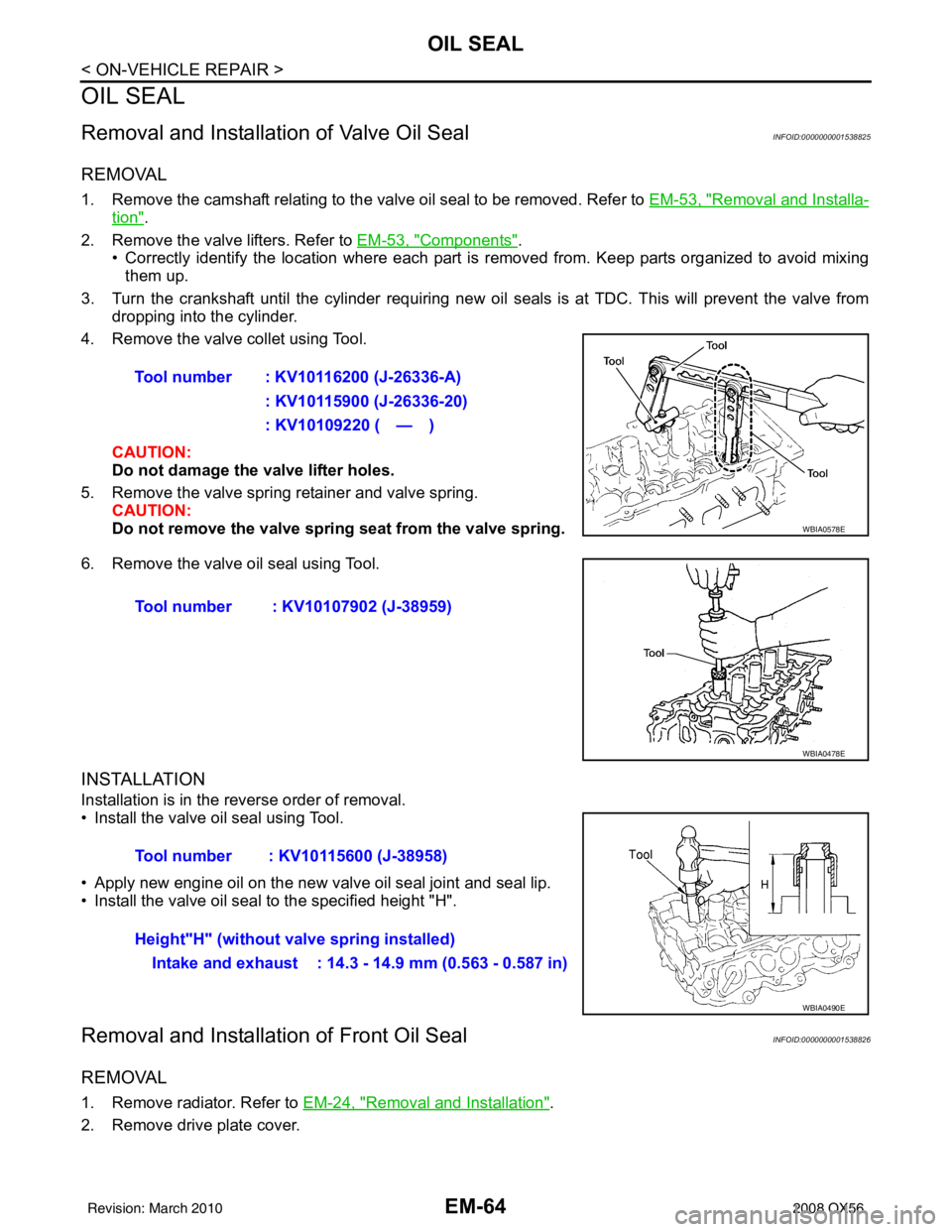
4. Remove the valve collet using Tool.
CAUTION:
Do not damage the valve lifter holes.
5. Remove the valve spring retainer and valve spring. CAUTION:
Do not remove the valve spring seat from the valve spring.
6. Remove the valve oil seal using Tool.
INSTALLATION
Installation is in the reverse order of removal.
• Install the valve oil seal using Tool.
• Apply new engine oil on the new valve oil seal joint and seal lip.
• Install the valve oil seal to the specified height "H".
Removal and Installation of Front Oil SealINFOID:0000000001538826
REMOVAL
1. Remove radiator. Refer to EM-24, "Removal and Installation".
2. Remove drive plate cover. Tool number : KV10116200 (J-26336-A)
: KV10115900 (J-26336-20)
: KV10109220 ( — )
WBIA0578E
Tool number : KV10107902 (J-38959)
WBIA0478E
Tool number : KV10115600 (J-38958)
Height"H" (without valve spring installed)Intake and exhaust : 14.3 - 14.9 mm (0.563 - 0.587 in)
WBIA0490E
Revision: March 2010 2008 QX56
Page 1882 of 4083

ENGINE ASSEMBLYEM-79
< REMOVAL AND INSTALLATION >
C
DE
F
G H
I
J
K L
M A
EM
NP
O
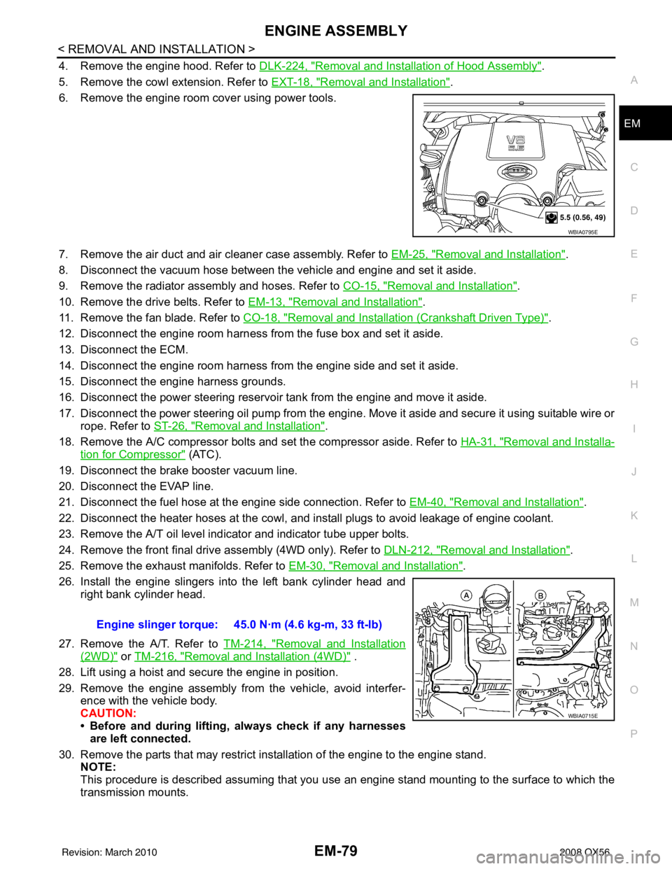
4. Remove the engine hood. Refer to
DLK-224, "Removal and Installation of Hood Assembly".
5. Remove the cowl extension. Refer to EXT-18, "
Removal and Installation".
6. Remove the engine room cover using power tools.
7. Remove the air duct and air cleaner case assembly. Refer to EM-25, "
Removal and Installation".
8. Disconnect the vacuum hose between the vehicle and engine and set it aside.
9. Remove the radiator assembly and hoses. Refer to CO-15, "
Removal and Installation".
10. Remove the drive belts. Refer to EM-13, "
Removal and Installation".
11. Remove the fan blade. Refer to CO-18, "
Removal and Installation (Crankshaft Driven Type)".
12. Disconnect the engine room harness from the fuse box and set it aside.
13. Disconnect the ECM.
14. Disconnect the engine room harness from the engine side and set it aside.
15. Disconnect the engine harness grounds.
16. Disconnect the power steering reservoir t ank from the engine and move it aside.
17. Disconnect the power steering oil pump from the engine. Move it aside and secure it using suitable wire or rope. Refer to ST-26, "
Removal and Installation".
18. Remove the A/C compressor bolts and set the compressor aside. Refer to HA-31, "
Removal and Installa-
tion for Compressor" (ATC).
19. Disconnect the brake booster vacuum line.
20. Disconnect the EVAP line.
21. Disconnect the fuel hose at the engine side connection. Refer to EM-40, "
Removal and Installation".
22. Disconnect the heater hoses at the cowl, and in stall plugs to avoid leakage of engine coolant.
23. Remove the A/T oil level indicator and indicator tube upper bolts.
24. Remove the front final drive assembly (4WD only). Refer to DLN-212, "
Removal and Installation".
25. Remove the exhaust manifolds. Refer to EM-30, "
Removal and Installation".
26. Install the engine slingers into the left bank cylinder head and right bank cylinder head.
27. Remove the A/T. Refer to TM-214, "
Removal and Installation
(2WD)" or TM-216, "Removal and Installation (4WD)" .
28. Lift using a hoist and secure the engine in position.
29. Remove the engine assembly from the vehicle, avoid interfer- ence with the vehicle body.
CAUTION:
• Before and during lifting, always check if any harnessesare left connected.
30. Remove the parts that may restrict installation of the engine to the engine stand. NOTE:
This procedure is described assuming that you use an engine stand mounting to the surface to which the
transmission mounts.
WBIA0795E
Engine slinger torque: 45.0 N·m (4.6 kg-m, 33 ft-lb)
WBIA0715E
Revision: March 2010 2008 QX56
Page 2061 of 4083

EXT-8
< SERVICE INFORMATION >
SQUEAK AND RATTLE TROUBLE DIAGNOSES
Most of these incidents can be repaired by adjusting, securing or insulating the item(s) or component(s) caus-
ing the noise.
SUNROOF/HEADLINING
Noises in the sunroof/headlining area c an often be traced to one of the following:
1. Sunroof lid, rail, linkage or seals making a rattle or light knocking noise
2. Sun visor shaft shaking in the holder
3. Front or rear windshield touching headliner and squeaking
Again, pressing on the components to stop the noise while duplicating the conditions can isolate most of these
incidents. Repairs usually consist of insulating with felt cloth tape.
OVERHEAD CONSOLE (FRONT AND REAR)
Overhead console noises are often caused by the c onsole panel clips not being engaged correctly. Most of
these incidents are repaired by pushing up on the c onsole at the clip locations until the clips engage.
In addition look for:
1. Loose harness or harness connectors.
2. Front console map/reading lamp lens loose.
3. Loose screws at console attachment points.
SEATS
When isolating seat noise it's important to note the pos ition the seat is in and the load placed on the seat when
the noise is present. These conditions should be duplicated when verifying and isolating the cause of the
noise.
Cause of seat noise include:
1. Headrest rods and holder
2. A squeak between the seat pad cushion and frame
3. The rear seatback lock and bracket
These noises can be isolated by moving or pressing on the suspected components while duplicating the con-
ditions under which the noise occurs. Most of thes e incidents can be repaired by repositioning the component
or applying urethane tape to the contact area.
UNDERHOOD
Some interior noise may be caused by components under the hood or on the engine wall. The noise is then
transmitted into the passenger compartment.
Causes of transmitted underhood noise include:
1. Any component installed to the engine wall
2. Components that pass through the engine wall
3. Engine wall mounts and connectors
4. Loose radiator installation pins
5. Hood bumpers out of adjustment
6. Hood striker out of adjustment
These noises can be difficult to isolate since they cannot be reached from the interior of the vehicle. The best
method is to secure, move or insulate one component at a time and test drive the \
vehicle. Also, engine RPM
or load can be changed to isolate the noise. Repairs can usually be made by moving, adjusting, securing, or
insulating the component causing the noise.
Revision: March 2010 2008 QX56
Page 2141 of 4083

FSU-24
< SERVICE DATA AND SPECIFICATIONS (SDS)
SERVICE DATA AND SPECIFICATIONS (SDS)
SERVICE DATA AND SPECIFICATIONS (SDS)
SERVICE DATA AND SPECIFICATIONS (SDS)
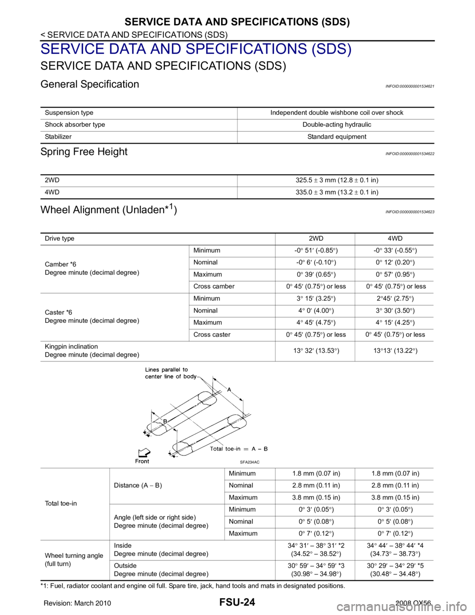
General SpecificationINFOID:0000000001534621
Spring Free HeightINFOID:0000000001534622
Wheel Alignment (Unladen*1)INFOID:0000000001534623
*1: Fuel, radiator coolant and engine oil full. Spare tire, jack, hand tools and mats in designated positions.Suspension type
Independent double wishbone coil over shock
Shock absorber type Double-acting hydraulic
Stabilizer Standard equipment
2WD325.5 ± 3 mm (12.8 ± 0.1 in)
4WD 335.0 ± 3 mm (13.2 ± 0.1 in)
Drive type 2WD 4WD
Camber *6
Degree minute (decimal degree) Minimum
-0° 51 ′ (-0.85 °)- 0° 33 ′ (-0.55 °)
Nominal -0° 6 ′ (-0.10 °)0 ° 12 ′ (0.20 °)
Maximum 0° 39 ′ (0.65 °)0 ° 57 ′ (0.95 °)
Cross camber 0° 45 ′ (0.75 °) or less 0 ° 45 ′ (0.75 °) or less
Caster *6
Degree minute (decimal degree) Minimum
3° 15 ′ (3.25 °)2 °45 ′ (2.75 °)
Nominal 4° 0 ′ (4.00 °)3 ° 30 ′ (3.50 °)
Maximum 4° 45 ′ (4.75 °)4 ° 15 ′ (4.25 °)
Cross caster 0° 45 ′ (0.75 °) or less 0
° 45 ′ (0.7
5°) or less
Kingpin inclination
Degree minute (decimal degree) 13
° 32 ′ (13.53 °)1 3°13 ′ (13.22 °)
To t a l t o e - i n Distance (A
− B) Minimum
1.8 mm (0.07 in) 1.8 mm (0.07 in)
Nominal 2.8 mm (0.11 in) 2.8 mm (0.11 in)
Maximum 3.8 mm (0.15 in) 3.8 mm (0.15 in)
Angle (left side or right side)
Degree minute (decimal degree) Minimum
0° 3 ′ (0.05 °)0 ° 3 ′ (0.05 °)
Nominal 0° 5 ′ (0.08 °)0 ° 5 ′ (0.08 °)
Maximum 0° 7 ′ (0.12 °)0 ° 7 ′ (0.12 °)
Wheel turning angle
(full turn) Inside
Degree minute (decimal degree)
34
° 31 ′ – 38 ° 31 ′ *2
(34.52 ° – 38.52 °) 34
° 44 ′ – 38° 44′ *4
(34.73 ° – 38.73 °)
Outs id
e
Degree minute (decimal degree) 30
° 59 ′ – 34 ° 59 ′ *3
(30.98 ° – 34.98 °) 30
° 29 ′ – 34° 29′ *5
(30.48 ° – 34.48 °)
SFA234AC
Revision: March 2010 2008 QX56