2008 INFINITI QX56 Engine cooling system
[x] Cancel search: Engine cooling systemPage 2614 of 4083

MA-16
< ON-VEHICLE MAINTENANCE >
ENGINE MAINTENANCE
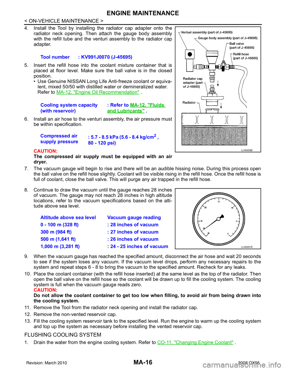
4. Install the Tool by installing the radiator cap adapter onto theradiator neck opening. Then attach the gauge body assembly
with the refill tube and the venturi assembly to the radiator cap
adapter.
5. Insert the refill hose into the coolant mixture container that is placed at floor level. Make sure the ball valve is in the closed
position.
• Use Genuine NISSAN Long Life Anti-freeze coolant or equiva-
lent, mixed 50/50 with distilled water or demineralized water.
Refer to MA-12, "
Engine Oil Recommendation" .
6. Install an air hose to the venturi assembly, the air pressure must be within specification.
CAUTION:
The compressed air supply must be equipped with an air
dryer.
7. The vacuum gauge will begin to rise and there will be an audible hissing noise. During this process open the ball valve on the refill hose slightly. Coolant will be vi sible rising in the refill hose. Once the refill hose is
full of coolant, close the ball valve. This will purge any air trapped in the refill hose.
8. Continue to draw the vacuum until the gauge reaches 28 inches of vacuum. The gauge may not reach 28 inches in high altitude
locations, refer to the vacuum specifications based on the alti-
tude above sea level.
9. When the vacuum gauge has reached the specifi ed amount, disconnect the air hose and wait 20 seconds
to see if the system loses any vacuum. If the vacuum level drops, perform any necessary repairs to the
system and repeat steps 6 - 8 to bring the vacuum to the specified amount. Recheck for any leaks.
10. Place the coolant container (with the refill hose insert ed) at the same level as the top of the radiator. Then
open the ball valve on the refill hose so the coolant will be drawn up to fill the cooling system. The cooling
system is full when the vacuum gauge reads zero.
CAUTION:
Do not allow the coolant container to get too low when filling, to avoid air from being drawn into
the cooling system.
11. Remove the Tool from the radiator neck opening and install the radiator cap.
12. Remove the non-vented reservoir cap.
13. Fill the cooling system reservoir tank to the specif ied level. Run the engine to warm up the cooling system
and top up the system as necessary before installing the vented reservoir cap.
FLUSHING COOLING SYSTEM
1. Drain the water from the engine cooling system. Refer to CO-11, "Changing Engine Coolant" .
Tool number : KV991J0070 (J-45695)
Cooling system capacity
(with reservoir)
: Refer to
MA-12, "
Fluids
and Lubricants" .
Compressed air
supply pressure : 5.7 - 8.5 kPa (5.6 - 8.4 kg/cm
2 ,
80 - 120 psi)
LLIA0058E
Altitude above sea level Vacuum gauge reading
0 - 100 m (328 ft) : 28 inches of vacuum
300 m (984 ft) : 27 inches of vacuum
500 m (1,641 ft) : 26 inches of vacuum
1,000 m (3,281 ft) : 24 - 25 inches of vacuum
LLIA0057E
Revision: March 2010 2008 QX56
Page 2615 of 4083

ENGINE MAINTENANCEMA-17
< ON-VEHICLE MAINTENANCE >
C
DE
F
G H
I
J
K L
M B
MA
N
O A
2. Fill the radiator and the reservoir tank (to the “MAX”
line), with water. Reinstall the radiator cap and leave
the vented reservoir cap off.
3. Run the engine until it reaches normal operating temperature.
4. Press the engine accelerator two or three times under no-load.
5. Stop the engine and wait until it cools down.
6. Drain the water from the engine cooling system. Refer to CO-11, "
Changing Engine Coolant" .
7. Repeat steps 2 through 6 until clear water begins to drain from the radiator.
Checking Fuel LineINFOID:0000000001606172
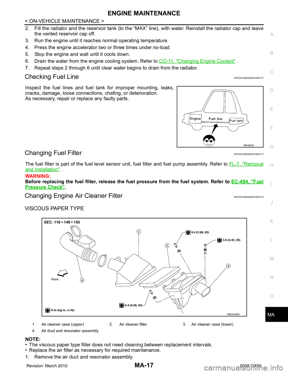
Inspect the fuel lines and fuel tank for improper mounting, leaks,
cracks, damage, loose connections, chafing, or deterioration.
As necessary, repair or replace any faulty parts.
Changing Fuel FilterINFOID:0000000001606173
The fuel filter is part of the fuel level sensor unit, fuel filter and fuel pump assembly. Refer to FL-7, "Removal
and Installation" .
WARNING:
Before replacing the fuel filter, release the fuel pressure from the fuel system. Refer to EC-494, "
Fuel
Pressure Check".
Changing Engine Air Cleaner FilterINFOID:0000000001606174
VISCOUS PAPER TYPE
NOTE:
• The viscous paper type filter does not need cleaning between replacement intervals.
• Replace the air filter as necessary for required maintenance.
1. Remove the air duct and resonator assembly.
SMA803A
1. Air cleaner case (upper) 2. Air cleaner filter3. Air cleaner case (lower)
4. Air duct and resonator assembly
WBIA0465E
Revision: March 2010 2008 QX56
Page 2745 of 4083
![INFINITI QX56 2008 Factory Service Manual PCS-12
< FUNCTION DIAGNOSIS >[IPDM E/R]
DIAGNOSIS SYSTEM (IPDM E/R)
DIAGNOSIS SYSTEM (IPDM E/R)
Diagnosis DescriptionINFOID:0000000001696490
AUTO ACTIVE TEST
Description
In auto active test mode, the INFINITI QX56 2008 Factory Service Manual PCS-12
< FUNCTION DIAGNOSIS >[IPDM E/R]
DIAGNOSIS SYSTEM (IPDM E/R)
DIAGNOSIS SYSTEM (IPDM E/R)
Diagnosis DescriptionINFOID:0000000001696490
AUTO ACTIVE TEST
Description
In auto active test mode, the](/manual-img/42/57030/w960_57030-2744.png)
PCS-12
< FUNCTION DIAGNOSIS >[IPDM E/R]
DIAGNOSIS SYSTEM (IPDM E/R)
DIAGNOSIS SYSTEM (IPDM E/R)
Diagnosis DescriptionINFOID:0000000001696490
AUTO ACTIVE TEST
Description
In auto active test mode, the IPDM
E/R sends a drive signal to the follo wing systems to check their operation.
• Oil pressure low/coolant pressure high warning indicator
• Oil pressure gauge
• Rear window defogger
• Front wipers
• Tail, license and parking lamps
• Front fog lamps
• Headlamps (Hi, Lo)
• A/C compressor (magnetic clutch)
• Cooling fan
Operation Procedure
1. Close the hood and front door RH, and lift the wiper a rms from the windshield (to prevent windshield dam-
age due to wiper operation).
NOTE:
When auto active test is performed with hood opened, sprinkle water on windshield before hand.
2. Turn ignition switch OFF.
3. Turn the ignition switch ON and, within 20 seconds, press the front door switch LH 10 times. Then turn the ignition switch OFF.
4. Turn the ignition switch ON within 10 seconds. Af ter that the horn sounds once and the auto active test
starts.
5. After a series of the following operations is repeated 3 times, auto active test is completed.
NOTE:
When auto active test mode has to be cancelled halfway through test, turn ignition switch OFF.
CAUTION:
• If auto active test mode cannot be actuated, check door switch system. Refer to DLK-67, "
Descrip-
tion".
• Do not start the engine.
Inspection in Auto Active Test Mode
When auto active test mode is actuated, the following 7 steps are repeated 3 times.
Operation
sequence Inspection Location
Operation
1 Rear window defogger 10 seconds
2 Front wipers LO for 5 seconds → HI for 5 seconds
WKIA4655E
Revision: March 2010 2008 QX56
Page 3310 of 4083
![INFINITI QX56 2008 Factory Service Manual SEC-102
< ECU DIAGNOSIS >[WITH INTELLIGENT KEY SYSTEM]
IPDM E/R (INTELLIGENT POWER DI
STRIBUTION MODULE ENGINE ROOM)
24 L Cooling fan relay Output — Conditions correct for cooling
fan operation
Bat INFINITI QX56 2008 Factory Service Manual SEC-102
< ECU DIAGNOSIS >[WITH INTELLIGENT KEY SYSTEM]
IPDM E/R (INTELLIGENT POWER DI
STRIBUTION MODULE ENGINE ROOM)
24 L Cooling fan relay Output — Conditions correct for cooling
fan operation
Bat](/manual-img/42/57030/w960_57030-3309.png)
SEC-102
< ECU DIAGNOSIS >[WITH INTELLIGENT KEY SYSTEM]
IPDM E/R (INTELLIGENT POWER DI
STRIBUTION MODULE ENGINE ROOM)
24 L Cooling fan relay Output — Conditions correct for cooling
fan operation
Battery voltage
Conditions not correct for
cooling fan operation 0V
26 P/L Headlamp aiming mo-
tors Output —Lighting
switch 2nd
position or
AUTO, head-
lamp aiming
switch in po-
sition OFF
0V
ON Battery voltage
27 W/B Fuse 38 Output —Ignition switch ON or START
Battery voltage
Ignition switch OFF or ACC 0V
30 W Fuse 53 Output —Ignition switch ON or START
Battery voltage
Ignition switch OFF or ACC 0V
32 L Wiper low speed sig-
nal OutputON or
START Wiper switch OFF
Battery voltage
LO or INT 0V
35 L/B Wiper high speed sig-
nal OutputON or
START Wiper switch OFF, LO, INT Battery voltage
HI 0V
37 Y Power generation
command signal
Output —Ignition switch ON
6.3 V
40% is set on "Active test,"
"ALTERNATOR DUTY" of
"ENGINE" 3.8 V
40% is set on "Active test,"
"ALTERNATOR DUTY" of
"ENGINE" 1.4 V
38 B Ground Input ——0V
39 L CAN-H — ON— —
40 P CAN-L — ON— —
Te r m i n a l
Wire
color Signal name Signal
input/
output Measuring condition
Reference value(Approx.)
Igni-
tion
switch Operation or condition
JPMIA0001GB
JPMIA0002GB
JPMIA0003GB
Revision: March 2010
2008 QX56
Page 3317 of 4083
![INFINITI QX56 2008 Factory Service Manual IPDM E/R (INTELLIGENT POWER DISTRIBUTION MODULE ENGINE ROOM)
SEC-109
< ECU DIAGNOSIS > [WITH INTELLIGENT KEY SYSTEM]
C
D
E
F
G H
I
J
L
M A
B
SEC
N
O P
If No CAN Communication Is Available With BCM
IGN INFINITI QX56 2008 Factory Service Manual IPDM E/R (INTELLIGENT POWER DISTRIBUTION MODULE ENGINE ROOM)
SEC-109
< ECU DIAGNOSIS > [WITH INTELLIGENT KEY SYSTEM]
C
D
E
F
G H
I
J
L
M A
B
SEC
N
O P
If No CAN Communication Is Available With BCM
IGN](/manual-img/42/57030/w960_57030-3316.png)
IPDM E/R (INTELLIGENT POWER DISTRIBUTION MODULE ENGINE ROOM)
SEC-109
< ECU DIAGNOSIS > [WITH INTELLIGENT KEY SYSTEM]
C
D
E
F
G H
I
J
L
M A
B
SEC
N
O P
If No CAN Communication Is Available With BCM
IGNITION RELAY MALFUNCTION DETECTION FUNCTION
• IPDM E/R monitors the voltage at the contact circuit and excitation coil circuit of the ignition relay inside it.
• IPDM E/R judges the ignition relay error if the voltage differs between the contact circuit and the excitation
coil circuit.
• If the ignition relay cannot turn OFF due to contact seizure, it activates the tail lamp relay for 10 minutes to alert the user to the ignition relay malfunction when the ignition switch is turned OFF.
NOTE:
The tail lamp turns OFF when the ignition switch is turned ON.
FRONT WIPER CONTROL
IPDM E/R detects front wiper stop posit ion by a front wiper auto stop signal.
When a front wiper auto stop signal is in the conditions listed below, IPDM E/R stops power supply to wiper
after repeating a front wiper 10 second activation and 20 second stop five times.
NOTE:
This operation status can be confirmed on the IPDM E/R “DATA MONITOR” that displays “Block” for the item
“WIP PROT” while the wiper is stopped.
STARTER MOTOR PROTECTION FUNCTION
IPDM E/R turns OFF the starter control relay to protect the starter motor when the starter control relay remains
active for 90 seconds.
Control part Fail-safe in operation
Cooling fan • Turns ON the cooling fan relay when the ignition switch is turned ON
• Turns OFF the cooling fan relay when the ignition switch is turned OFF
Control part
Fail-safe in operation
Headlamp • Turns ON the headlamp low relay when the ignition switch is turned ON
• Turns OFF the headlamp low relay when the ignition switch is turned OFF
• Headlamp high relay OFF
•Parking lamps
• License plate lamps
• Tail lamps • Turns ON the tail lamp relay when the ignition switch is turned ON
• Turns OFF the tail lamp relay when the ignition switch is turned OFF
Front wiper • The status just before activation of fail-safe control is maintained until the ignition
switch is turned OFF while the front wiper is operating at LO or HI speed.
• The wiper is operated at LO speed until the ignition switch is turned OFF if the fail- safe control is activated while the front wipe r is set in the INT mode and the front wiper
motor is operating.
Rear window defogger Rear window defogger relay OFF
A/C compressor A/C relay OFF
Front fog lamps Front fog lamp relay OFF
Ignition switch Ignition relayTail lamp relay
ON ON —
OFF OFF —
Ignition switchFront wiper switch Auto stop signal
ON OFF
Front wiper stop position signal cannot be
input 10 seconds.
ON The signal does not change for 10 seconds.
Revision: March 2010 2008 QX56
Page 3574 of 4083

A/T CONTROL SYSTEMTM-27
< FUNCTION DIAGNOSIS >
CEF
G H
I
J
K L
M A
B
TM
N
O P
FUNCTION OF PRESSURE SWITCH
Pilot valve A Adjusts the line pressure and produces the constant pressure (pilot pressure) required
for line pressure control, shift change control, and lock-up control.
Pilot valve B Adjusts the line pressure and produces the constant pressure (pilot pressure) required
for shift change control.
Low coast brake switching valve During engine braking, supplies the line pressure to the low coast brake reducing valve.
Low coast brake reducing valve When the low coast brake is coupled, adjusts the line pressure to the optimum pressure
(low coast brake pressure) and supplies it to the low coast brake.
N-R accumulator Produces the stabilizing pressure for when N-R is selected.
Direct clutch piston switching valve Operates in 4GR gear and switches the direct clutch coupling capacity.
High and low reverse clutch control valve When the high and low reverse clutch is coupled, adjusts the line pressure to the opti-
mum pressure (high and low reverse clutch pressure) and supplies it to the high and low
reverse clutch. (In 1GR, 3GR, 4GR and 5GR, adjusts the clutch pressure.)
Input clutch control valve When the input clutch is coupled, adjusts the line pressure to the optimum pressure (in-
put clutch pressure) and supplies it to the input clutch. (In 4GR and 5GR, adjusts the
clutch pressure.)
Direct clutch control valve When the direct clutch is coupled, adjusts the line pressure to the optimum pressure (di-
rect clutch pressure) and supplies it to the direct clutch. (In 2GR, 3GR, and 4GR, adjusts
the clutch pressure.)
TCC control valve
TCC control plug
TCC control sleeve Switches the lock-up to operating or released. Also, by performing the lock-up operation
transiently, lock-up smoothly.
Torque converter lubrication valve Operates during lock-up to switch the torque converter, cooling, and lubrication system
oil path.
Cool bypass valve Allows excess oil to bypass cooler circuit without being fed into it.
Line pressure relief valve Discharges excess oil from line pressure circuit.
N-D accumulator Produces the stabilizing pressure for when N-D is selected.
Manual valve Sends line pressure to each circuit according to the select position. The circuits to which
the line pressure is not sent drain.
Name
Function
Name Function
Pressure switch 2 (LC/B) Detects any malfunction in the low coast brake hydraulic pressure. When it detects any
malfunction, it puts the system into fail-safe mode.
Revision: March 2010
2008 QX56
Page 3857 of 4083

HEATER & COOLING UNIT ASSEMBLYVTL-17
< ON-VEHICLE REPAIR >
C
DE
F
G H
J
K L
M A
B
VTL
N
O P
1. Move the two front seats to the rear most position on the seat track.
2. Disconnect the battery negative terminal and battery positive terminal.
3. Discharge the refrigerant from the A/C system. Refer to HA-20, "
HFC-134a (R-134a) Service Procedure".
4. Drain the coolant from the engine cooling system. Refer to CO-11, "
Changing Engine Coolant".
5. Disconnect the front heater hoses from the front heater core.
6. Disconnect the high/low pressure pipes from the front expansion valve.
7. Remove the instrument panel and console panel. Refer to IP-12, "
Removal and Installation".
8. Remove the steering column. Refer to ST-20, "
Removal and Installation".
9. Disconnect the instrument panel wire harness at t he RH and LH in-line connector brackets, and the fuse
block (J/B) electrical connectors. Refer to PG-9, "
Wiring Diagram — Battery Power Supply —".
10. Disconnect the steering member from each side of the vehicle body.
11. Remove the front heater and cooling unit assembly with it attached to the steering member, from the vehi- cle.
CAUTION:
Use care not to damage the seats and interior trim panels when removing the front heater and
cooling unit assembly with it at tached to the steering member.
12. Remove the front heater and cooling uni t assembly from the steering member.
Installation
Installation is in the reverse order of removal.
CAUTION:
• Replace the O-ring of the low-pressure pipe and high-pressure pipe with a new one, and apply com-
pressor oil to it when installing it.
• After charging the refrigerant, check for leaks.
NOTE:
• Fill the engine cooling system with the specified coolant mixture. Refer to CO-11, "
Changing Engine Cool-
ant".
• Recharge the A/C system. Refer to HA-20, "
HFC-134a (R-134a) Service Procedure".
REAR HEATER AND COOLING UNIT ASSEMBLY
Removal
1. Discharge the refrigerant from the A/C system. Refer to HA-20, "HFC-134a (R-134a) Service Procedure".
2. Drain the coolant from the engine cooling system. Refer to CO-11, "
Changing Engine Coolant".
3. Remove the luggage side finisher lower RH. Refer to INT-19, "
Removal and Installation".
4. Disconnect the rear heater core hoses from the rear heater core.
5. Disconnect the rear A/C pipes from the rear expansion valve.
6. Disconnect the following electrical connectors: • Rear blower motor
• Rear variable blower control
• Rear air mix door motor
7. Disconnect the ducts from the rear heater and cooling unit assembly.
8. Remove the rear heater and cooling unit assembly.
Installation
Installation is in the reverse order of removal.
CAUTION:
• Replace the O-ring of the low-pressure pipe and high-pressure pipe with a new one, and apply com- pressor oil to it when installing it.
• After charging the refrigerant, check for leaks.
NOTE:
• Fill the engine cooling system with the specified coolant mixture. Refer to CO-11, "
Changing Engine Cool-
ant".
• Recharge the A/C system. Refer to HA-20, "
HFC-134a (R-134a) Service Procedure".
Revision: March 2010 2008 QX56
Page 3860 of 4083

VTL-20
< ON-VEHICLE REPAIR >
HEATER CORE
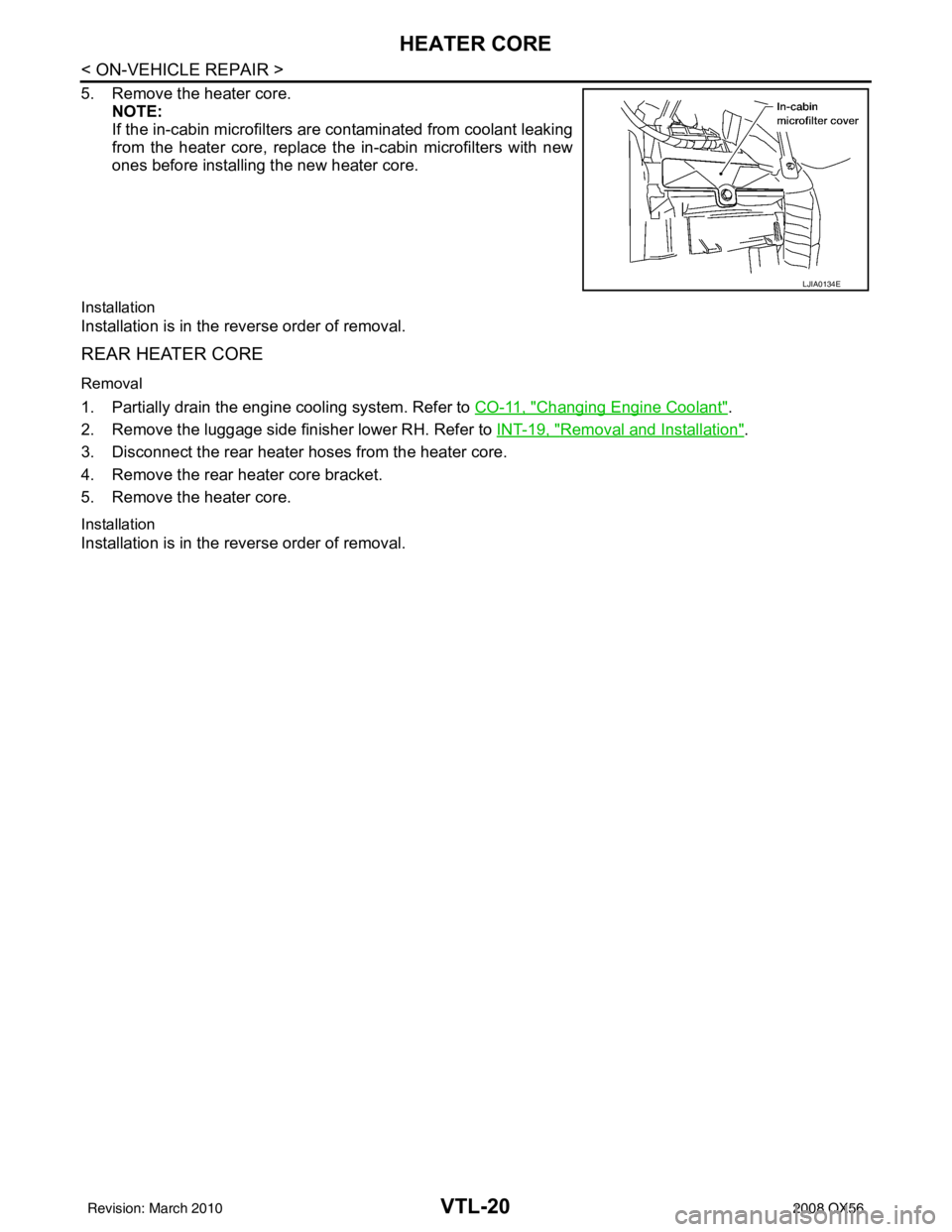
5. Remove the heater core.NOTE:
If the in-cabin microfilters are c ontaminated from coolant leaking
from the heater core, replace the in-cabin microfilters with new
ones before installing the new heater core.
Installation
Installation is in the reverse order of removal.
REAR HEATER CORE
Removal
1. Partially drain the engine cooling system. Refer to CO-11, "Changing Engine Coolant".
2. Remove the luggage side finisher lower RH. Refer to INT-19, "
Removal and Installation".
3. Disconnect the rear heater hoses from the heater core.
4. Remove the rear heater core bracket.
5. Remove the heater core.
Installation
Installation is in the reverse order of removal.
LJIA0134E
Revision: March 2010 2008 QX56