2008 INFINITI QX56 Engine cooling system
[x] Cancel search: Engine cooling systemPage 1605 of 4083
![INFINITI QX56 2008 Factory Service Manual EC-306
< COMPONENT DIAGNOSIS >[VK56DE]
P1217 ENGINE OVER TEMPERATURE
P1217 ENGINE OVER TEMPERATURE
On Board Diagn
osis LogicINFOID:0000000001351714
NOTE:
•If DTC P1217 is displayed with DTC U1000 or INFINITI QX56 2008 Factory Service Manual EC-306
< COMPONENT DIAGNOSIS >[VK56DE]
P1217 ENGINE OVER TEMPERATURE
P1217 ENGINE OVER TEMPERATURE
On Board Diagn
osis LogicINFOID:0000000001351714
NOTE:
•If DTC P1217 is displayed with DTC U1000 or](/manual-img/42/57030/w960_57030-1604.png)
EC-306
< COMPONENT DIAGNOSIS >[VK56DE]
P1217 ENGINE OVER TEMPERATURE
P1217 ENGINE OVER TEMPERATURE
On Board Diagn
osis LogicINFOID:0000000001351714
NOTE:
•If DTC P1217 is displayed with DTC U1000 or U1001, first perform the trouble diagnosis for DTC
U1000, U1001. Refer to EC-87
.
• If DTC P1217 is displayed with DTC U1010, first pe rform the trouble diagnosis for DTC U1010. Refer
to EC-88
.
If the cooling fan or another component in the cooling system malfunctions, engine coolant temperature will
rise.
When the engine coolant temperature reaches an abnorma lly high temperature condition, a malfunction is
indicated.
This self-diagnosis has the one trip detection logic.
CAUTION:
When a malfunction is indicated, be sure to replace the coolant. Refer to CO-11, "
Changing Engine
Coolant". Also, replace the engine oil. Refer to LU-9, "Changing Engine Oil".
1. Fill radiator with coolant up to specified level with a filling speed of 2 liters per minute. Be sure to
use coolant with the proper mixture ratio. Refer to CO-10
.
2. After refilling coolant, run engine to en sure that no water-flow noise is emitted.
Overall Function CheckINFOID:0000000001351715
Use this procedure to check the overall function of the cooling fan. During this check, a DTC might not be con-
firmed.
WARNING:
Never remove the radiator cap and/or reservoir tank cap when the engine is hot. Serious burns could
be caused by high pressure fluid escaping fr om the radiator and/or reservoir tank.
Wrap a thick cloth around cap. Carefully remove the cap by turning it a quarter turn to allow built-up
pressure to escape. Then turn the cap all the way off.
WITH CONSULT-III
1. Check the coolant level in the reservoir tank and radiator. Allow engine to cool before checking coolant level.
If the coolant level in the reservoir tank and/or radiator is below
the proper range, skip the following steps and go to EC-395,
"Diagnosis Procedure".
2. Confirm whether customer filled the coolant or not. If customer
filled the coolant, skip the following steps and go to EC-395,
"Diagnosis Procedure".
3. Turn ignition switch ON.
DTC No. Trouble diagnosis name DTC detecting condition Possible cause
P1217
1217 Engine over tempera-
ture (Overheat) • Cooling fan does not operate properly (Over-
heat).
• Cooling fan system does not operate proper-
ly (Overheat).
• Engine coolant was not added to the system using the proper filling method.
• Engine coolant is not within the specified range. • Harness or connectors
(The cooling fan circuit is open or short-
ed.)
• Cooling fan
• Cooling fan (crankshaft diven)
• IPDM E/R (Cooling fan relay)
•Radiator hose
•Radiator
•Radiator cap
• Reservoir tank
• Reservoir tank cap
• Water pump
•Thermostat
For more informat ion, refer to EC-308,
"Main 13 Causes of Overheating".
SEF621W
Revision: March 2010 2008 QX56
Page 1607 of 4083
![INFINITI QX56 2008 Factory Service Manual EC-308
< COMPONENT DIAGNOSIS >[VK56DE]
P1217 ENGINE OVER TEMPERATURE
4. Make sure that cooling fan operates.
OK or NG
OK >> GO TO 4.
NG >> Check cooling fan control circuit. (Go to "PROCEDURE
A".)
4.C INFINITI QX56 2008 Factory Service Manual EC-308
< COMPONENT DIAGNOSIS >[VK56DE]
P1217 ENGINE OVER TEMPERATURE
4. Make sure that cooling fan operates.
OK or NG
OK >> GO TO 4.
NG >> Check cooling fan control circuit. (Go to "PROCEDURE
A".)
4.C](/manual-img/42/57030/w960_57030-1606.png)
EC-308
< COMPONENT DIAGNOSIS >[VK56DE]
P1217 ENGINE OVER TEMPERATURE
4. Make sure that cooling fan operates.
OK or NG
OK >> GO TO 4.
NG >> Check cooling fan control circuit. (Go to "PROCEDURE
A".)
4.CHECK COOLING SYSTEM FOR LEAK
Refer to CO-10, "
Inspection".
OK or NG
OK >> GO TO 5.
NG >> Check the following for leak. •Hose
• Radiator
• Radiator cap
• Water pump
• Reservoir tank
5.CHECK COMPONENT PARTS
Check the following.
• RESERVOIR TANK CAP (Refer to CO-10, "
Inspection".)
• Thermostat. (Refer to CO-22, "
Removal and Installation".)
• Engine coolant temperature sensor. (Refer to EC-126, "
Component Inspection".)
OK or NG
OK >> GO TO 6.
NG >> Replace malfunctioning component.
6.CHECK MAIN 13 CAUSES
If the cause cannot be isolated, go to EC-308, "
Main 13 Causes of Overheating".
>> INSPECTION END
Main 13 Causes of OverheatingINFOID:0000000001351718
SEF882V
Engine Step Inspection item EquipmentStandardReference page
OFF 1 • Blocked radiator • Blocked condenser
• Blocked radiator grille
• Blocked bumper • Visual
No blocking —
2 • Coolant mixture • Coolant tester 50 - 50% coolant mixtureCO-10
3 • Coolant level • VisualCoolant up to MAX level in
reservoir tank and radiator
filler neck CO-11, "Changing Engine
Coolant"
4 • Reservoir tank cap • Pre
ssure tester 95 - 125 kPa
(0.97 - 1.28 kg/cm2, 14 -
18 psi) (Limit) CO-10, "
Inspection"
ON*25 • Coolant leaks
• VisualNo leaks CO-10, "Inspection"
ON*26 • Thermostat • Touch the upper and
lower radiator hoses Both hoses should be hot
CO-22, "Removal and In-
stallation"
ON*17 • Cooling fan • CONSULT-IIIOperating See trouble diagnosis for
DTC P1217 ( EC-36
).
Revision: March 2010 2008 QX56
Page 1722 of 4083
![INFINITI QX56 2008 Factory Service Manual REFRIGERANT PRESSURE SENSOREC-423
< COMPONENT DIAGNOSIS > [VK56DE]
C
D
E
F
G H
I
J
K L
M A
EC
NP
O
REFRIGERANT PRESSURE SENSOR
Component DescriptionINFOID:0000000001365897
The refrigerant pressure sen INFINITI QX56 2008 Factory Service Manual REFRIGERANT PRESSURE SENSOREC-423
< COMPONENT DIAGNOSIS > [VK56DE]
C
D
E
F
G H
I
J
K L
M A
EC
NP
O
REFRIGERANT PRESSURE SENSOR
Component DescriptionINFOID:0000000001365897
The refrigerant pressure sen](/manual-img/42/57030/w960_57030-1721.png)
REFRIGERANT PRESSURE SENSOREC-423
< COMPONENT DIAGNOSIS > [VK56DE]
C
D
E
F
G H
I
J
K L
M A
EC
NP
O
REFRIGERANT PRESSURE SENSOR
Component DescriptionINFOID:0000000001365897
The refrigerant pressure sensor is installed at the condenser of the
air conditioner system. The sensor uses an electrostatic volume
pressure transducer to convert refrigerant pressure to voltage. The
voltage signal is sent to ECM, and ECM controls cooling fan system.
Diagnosis ProcedureINFOID:0000000001365899
1.CHECK REFRIGERANT PRESSURE
SENSOR OVERALL FUNCTION
1. Start engine and warm it up to normal operating temperature.
2. Turn A/C switch and blower fan switch ON.
3. Check voltage between ECM terminal 70 and ground with CON- SULT-IIl or tester.
OK or NG
OK >> INSPECTION END
NG >> GO TO 2.
2.CHECK GROUND CONNECTIONS
1. Turn A/C switch and blower fan switch OFF.
2. Turn ignition switch OFF.
3. Loosen and retighten three ground screws on the body.
BBIA0445E
PBIB2657E
Voltage: 1.0 - 4.0V
PBIB1188E
Revision: March 2010 2008 QX56
Page 1759 of 4083
![INFINITI QX56 2008 Factory Service Manual EC-460
< ECU DIAGNOSIS >[VK56DE]
ECM
• When there is an open circuit on MIL circuit, the ECM cannot warn the driver by lighting up MIL when there
is malfunction on engine control system.
Therefore, INFINITI QX56 2008 Factory Service Manual EC-460
< ECU DIAGNOSIS >[VK56DE]
ECM
• When there is an open circuit on MIL circuit, the ECM cannot warn the driver by lighting up MIL when there
is malfunction on engine control system.
Therefore,](/manual-img/42/57030/w960_57030-1758.png)
EC-460
< ECU DIAGNOSIS >[VK56DE]
ECM
• When there is an open circuit on MIL circuit, the ECM cannot warn the driver by lighting up MIL when there
is malfunction on engine control system.
Therefore, when electrical controlled throttle and pa rt of ECM related diagnoses are continuously detected
as NG for 5 trips, ECM warns the driver that engi ne control system malfunctions and MIL circuit is open by
means of operating fail-safe function.
The fail-safe function also operates when above diagnos es except MIL circuit are detected and demands the
driver to repair the malfunction.
DTC No. Detected items Engine operating condition in fail-safe mode
P0102
P0103 Mass air flow sensor circuit Engine speed will not rise more than 2,400 rpm due to the fuel cut.
P0117
P0118 Engine coolant tempera-
ture sensor circuit Engine coolant temperature will be determined by ECM based on the following condition.
CONSULT-IIl displays the engine coolant temperature decided by ECM.
Condition Engine coolant temperature decided
(CONSULT-IIl display)
Just as ignition switch is turned ON
or START 40
°C (104 °F)
Approx 4 minutes or more after en-
gine starting. 80
°C (176 °F)
Except as shown above 40 - 80
°C (104 - 176 °F)
(Depends on the time)
When the fail-safe system for engine coolant temperature sensor is activated, the cooling
fan operates while engine is running.
P0122
P0123
P0222
P0223
P2135 Throttle position sensor The ECM controls the electric throttle control actuator in regulating the throttle opening in
order for the idle position to be within +10 degrees.
The ECM regulates the opening speed of the throttle valve to be slower than the normal
condition.
So, the acceleration will be poor.
P0643 Sensor power supply ECM stops the electric throttle control actuator control, throttle valve is maintained at a fixed opening (approx. 5 degrees) by the return spring.
P2100
P2103 Throttle control motor relay ECM stops the electric throttle control actuator control, throttle valve is maintained at a
fixed opening (approx. 5 degrees) by the return spring.
P2101 Electric throttle control function ECM stops the electric throttle control actuator control, throttle valve is maintained at a
fixed opening (approx. 5 degrees) by the return spring.
P2118 Throttle control motor ECM stops the electric throttle control actuator control, throttle valve is maintained at a fixed opening (approx. 5 degrees) by the return spring.
P2119 Electric throttle control ac- tuator (When electric throttle control actuator does not function properly due to the return spring
malfunction:)
ECM controls the electric throttle actuator by regulating the throttle opening around the
idle position. The engine speed will not rise more than 2,000 rpm.
(When throttle valve opening angle in fail-safe mode is not in specified range:)
ECM controls the electric throttle control actuator by regulating the throttle opening to 20
degrees or less.
(When ECM detects the throttle valve is stuck open:)
While the vehicle is driving, it slows down gradually by fuel cut. After the vehicle stops, the
engine stalls.
The engine can restart in N or P position, and engine speed will not exceed 1,000 rpm or
more.
P2122
P2123
P2127
P2128
P2138 Accelerator pedal position
sensor
The ECM controls the electric throttle control actuator in regulating the throttle opening in
order for the idle position to be within +10 degrees.
The ECM regulates the opening speed of the throttle valve to be slower than the normal
condition.
So, the acceleration will be poor.
Engine operating condition in fail-safe mode
Engine speed will not rise more than 2,500 rpm due to the fuel cut
Revision: March 2010 2008 QX56
Page 1783 of 4083
![INFINITI QX56 2008 Factory Service Manual EC-484
< SYMPTOM DIAGNOSIS >[VK56DE]
ENGINE CONTROL SYSTEM SYMPTOMS
1 - 6: The numbers refer to the order of inspection.Exhaust Exhaust manifold/Tube/Muffler/
Gasket 55555 55 5EM-30
,
EX-
5Three way INFINITI QX56 2008 Factory Service Manual EC-484
< SYMPTOM DIAGNOSIS >[VK56DE]
ENGINE CONTROL SYSTEM SYMPTOMS
1 - 6: The numbers refer to the order of inspection.Exhaust Exhaust manifold/Tube/Muffler/
Gasket 55555 55 5EM-30
,
EX-
5Three way](/manual-img/42/57030/w960_57030-1782.png)
EC-484
< SYMPTOM DIAGNOSIS >[VK56DE]
ENGINE CONTROL SYSTEM SYMPTOMS
1 - 6: The numbers refer to the order of inspection.Exhaust Exhaust manifold/Tube/Muffler/
Gasket 55555 55 5EM-30
,
EX-
5Three way catalyst
Lubrica-
tion Oil pan/Oil strainer/Oil pump/Oil
filter/Oil gallery/Oil cooler
55555 55 5EM-33
,
LU-
14 , LU-11 ,
LU-12
Oil level (Low)/Filthy oil LU-8, "In-
spection"
Cooling Radiator/Hose/Radiator filler cap
55555 55 45 CO-15
Thermostat
5CO-22
Water pump CO-20
Water galleryCO-6
Cooling fan5CO-18,
CO-
19
Coolant level (Low)/Contaminat-
ed coolant 5
CO-10
IVIS (INFINITI Vehicle Immobilizer System —
NATS) 11
SEC-8
SYMPTOM
Reference
page
HARD/NO START/RESTART (EXCP. HA)
ENGINE STALL
HESITATION/SURGING/FLAT SPOT
SPARK KNOCK/DETONATION
LACK OF POWER/POOR ACCELERATION
HIGH IDLE/LOW IDLE
ROUGH IDLE/HUNTING
IDLING VIBRATION
SLOW/NO RETURN TO IDLE
OVERHEATS/WATER TEMPERATURE HIGH
EXCESSIVE FUEL CONSUMPTION
EXCESSIVE OIL CONSUMPTION
BATTERY DEAD (UNDER CHARGE)
Warranty symptom code AA AB AC AD AE AF AG AH AJ AK AL AM HA
Revision: March 2010 2008 QX56
Page 1833 of 4083

EM-30
< ON-VEHICLE REPAIR >
EXHAUST MANIFOLD AND THREE WAY CATALYST
EXHAUST MANIFOLD AND THREE WAY CATALYST
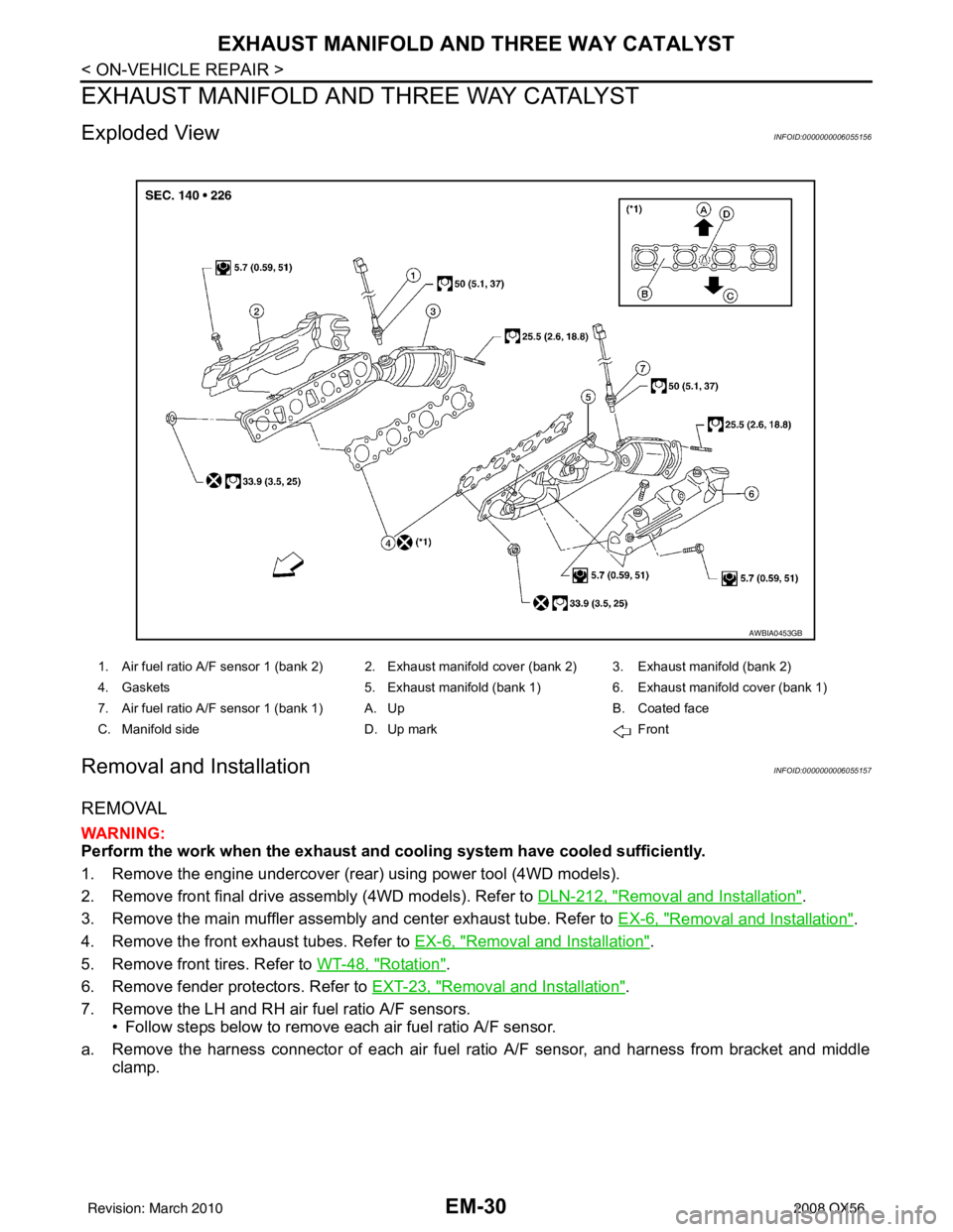
Exploded ViewINFOID:0000000006055156
Removal and InstallationINFOID:0000000006055157
REMOVAL
WARNING:
Perform the work when the exhaust and cooling system have cooled sufficiently.
1. Remove the engine undercover (rear) using power tool (4WD models).
2. Remove front final drive assembly (4WD models). Refer to DLN-212, "
Removal and Installation".
3. Remove the main muffler assembly and center exhaust tube. Refer to EX-6, "
Removal and Installation".
4. Remove the front exhaust tubes. Refer to EX-6, "
Removal and Installation".
5. Remove front tires. Refer to WT-48, "
Rotation".
6. Remove fender protectors. Refer to EXT-23, "
Removal and Installation".
7. Remove the LH and RH air fuel ratio A/F sensors. • Follow steps below to remove each air fuel ratio A/F sensor.
a. Remove the harness connector of each air fuel ra tio A/F sensor, and harness from bracket and middle
clamp.
1. Air fuel ratio A/F sensor 1 (bank 2) 2. Exhaust manifold cover (bank 2) 3. Exhaust manifold (bank 2)
4. Gaskets 5. Exhaust manifold (bank 1) 6. Exhaust manifold cover (bank 1)
7. Air fuel ratio A/F sensor 1 (bank 1) A. Up B. Coated face
C. Manifold side D. Up mark Front
AWBIA0453GB
Revision: March 2010 2008 QX56
Page 1855 of 4083

EM-52
< ON-VEHICLE REPAIR >
TIMING CHAIN
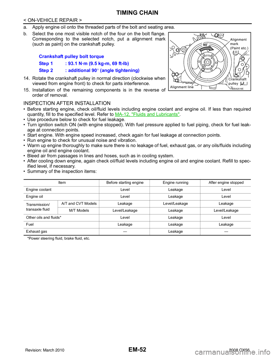
a. Apply engine oil onto the threaded parts of the bolt and seating area.
b. Select the one most visible notch of the four on the bolt flange.Corresponding to the selected notch, put a alignment mark
(such as paint) on the crankshaft pulley.
14. Rotate the crankshaft pulley in normal direction (clockwise when viewed from engine front) to check for parts interference.
15. Installation of the remaining components is in the reverse of order of removal.
INSPECTION AFTER INSTALLATION
• Before starting engine, check oil/fluid levels incl uding engine coolant and engine oil. If less than required
quantity, fill to the specified level. Refer to MA-12, "
Fluids and Lubricants".
• Use procedure below to check for fuel leakage.
• Turn ignition switch ON (with engine stopped). With fuel pressure applied to fuel piping, check for fuel leak- age at connection points.
• Start engine. With engine speed increased, che ck again for fuel leakage at connection points.
• Run engine to check for unusual noise and vibration.
• Warm up engine thoroughly to make sure there is no leakage of fuel, exhaust gas, or any oils/fluids including
engine oil and engine coolant.
• Bleed air from passages in lines and hoses, such as in cooling system.
• After cooling down engine, again check oil/fluid levels including engine oil and engine coolant. Refill to spec-
ified level, if necessary.
• Summary of the inspection items:
*Power steering fluid, brake fluid, etc.
Crankshaft pulley bolt torque
Step 1 : 93.1 N·m (9.5 kg-m, 69 ft-lb)
Step 2 : additional 90 ° (angle tightening)
KBIA2519E
Item Before starting engine Engine runningAfter engine stopped
Engine coolant LevelLeakage Level
Engine oil LevelLeakage Level
Transmission/
transaxle fluid A/T and CVT Models
LeakageLevel/Leakage Leakage
M/T Models Level/Leakage LeakageLevel/Leakage
Other oils and fluids* LevelLeakage Level
Fuel LeakageLeakage Leakage
Exhaust gas —Leakage —
Revision: March 2010 2008 QX56
Page 1872 of 4083

CYLINDER HEADEM-69
< ON-VEHICLE REPAIR >
C
DE
F
G H
I
J
K L
M A
EM
NP
O
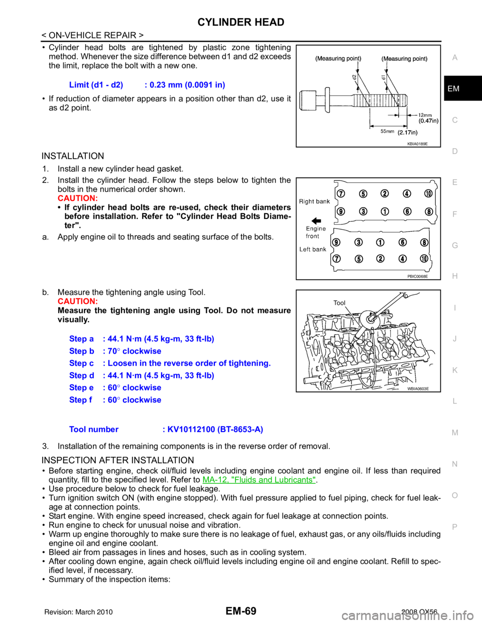
• Cylinder head bolts are tightened by plastic zone tightening
method. Whenever the size difference between d1 and d2 exceeds
the limit, replace the bolt with a new one.
• If reduction of diameter appears in a position other than d2, use it as d2 point.
INSTALLATION
1. Install a new cylinder head gasket.
2. Install the cylinder head. Follow the steps below to tighten the bolts in the numerical order shown.
CAUTION:
• If cylinder head bolts are re-used, check their diameters
before installation. Refer to "Cylinder Head Bolts Diame-
ter".
a. Apply engine oil to threads and seating surface of the bolts.
b. Measure the tightening angle using Tool. CAUTION:
Measure the tightening angl e using Tool. Do not measure
visually.
3. Installation of the remaining components is in the reverse order of removal.
INSPECTION AFTER INSTALLATION
• Before starting engine, check oil/fluid levels incl uding engine coolant and engine oil. If less than required
quantity, fill to the specified level. Refer to MA-12, "
Fluids and Lubricants".
• Use procedure below to check for fuel leakage.
• Turn ignition switch ON (with engine stopped). With fuel pressure applied to fuel piping, check for fuel leak-
age at connection points.
• Start engine. With engine speed increased, check again for fuel leakage at connection points.
• Run engine to check for unusual noise and vibration.
• Warm up engine thoroughly to make sure there is no leak age of fuel, exhaust gas, or any oils/fluids including
engine oil and engine coolant.
• Bleed air from passages in lines and hoses, such as in cooling system.
• After cooling down engine, again check oil/fluid levels including engine oil and engine coolant. Refill to spec- ified level, if necessary.
• Summary of the inspection items: Limit (d1 - d2) : 0.23 mm (0.0091 in)
KBIA0189E
PBIC0068E
Step a : 44.1 N·m (4.5 kg-m, 33 ft-lb)
Step b : 70°
clockwise
Step c : Loosen in the reverse order of tightening.
Step d : 44.1 N·m (4.5 kg-m, 33 ft-lb)
Step e : 60 ° clockwise
Step f : 60° clockwise
WBIA0603E
Tool number : KV10112100 (BT-8653-A)
Revision: March 2010 2008 QX56