2008 INFINITI QX56 engine
[x] Cancel search: enginePage 2210 of 4083

PRECAUTIONSHA-5
< PRECAUTION >
C
DE
F
G H
J
K L
M A
B
HA
N
O P
General Refrigerant PrecautionINFOID:0000000001516632
WARNING:
• Do not release refrigerant into the air. Use appr oved recovery/recycling equipment to capture the
refrigerant every time an air co nditioning system is discharged.
• Always wear eye and hand protection (goggles and gloves) when working with any refrigerant or air
conditioning system.
• Do not store or heat refrigerant containers above 52 °C (125° F).
• Do not heat a refrigerant containe r with an open flame; if container warming is required, place the
bottom of the container in a warm pail of water.
• Do not intentionally drop, puncture, or incinerate refrigerant containers.
• Keep refrigerant away from open flames: poison ous gas will be produced if refrigerant burns.
• Refrigerant will displace oxygen, therefore be certain to work in well ventilated areas to prevent suf- focation.
• Do not pressure test or leak test HFC-134a (R-134a) service equipment and/or vehicle air condition-
ing systems with compressed air during repair. Some mixtures of air and HFC-134a (R-134a) have
been shown to be combustible at elevated pressures. These mixtures, if ignited, may cause injury or
property damage. Additional health and safety information may be obtained from refrigerant manu-
facturers.
Precaution for Leak Detection DyeINFOID:0000000001516633
• The A/C system contains a fluorescent leak detection dy e used for locating refrigerant leaks. An ultraviolet
(UV) lamp is required to illuminate the dye when inspecting for leaks.
• Always wear fluorescence enhancing UV safety goggles to protect your eyes and enhance the visibility of
the fluorescent dye.
• The fluorescent dye leak detector is not a replacement for an electronic refrigerant leak detector. The fluo-
rescent dye leak detector should be used in conjuncti on with an electronic refrigerant leak detector (J-
41995).
• For your safety and the customer's satisfaction, read and follow all manufacturer's operating instructions and precautions prior to performing work.
• A compressor shaft seal should not be repaired because of dye seepage. The compressor shaft seal should
only be repaired after confirming the leak with an electronic refrigerant leak detector (J-41995).
• Always remove any dye from the leak area after repairs are complete to avoid a misdiagnosis during a future service.
• Do not allow dye to come into contact with paint ed body panels or interior components. If dye is spilled,
clean immediately with the approved dye cleaner. Fluorescent dye left on a surface for an extended period of
time cannot be removed.
• Do not spray the fluorescent dye cleaning agent on hot surfaces (engine exhaust manifold, etc.).
• Do not use more than one refrigerant dye bot tle (1/4 ounce / 7.4 cc) per A/C system.
• Leak detection dyes for HFC-134a (R-134a) and CFC-12 (R -12) A/C systems are different. Do not use HFC-
134a (R-134a) leak detection dye in CFC-12 (R-12) A/ C systems or CFC-12 (R-12) leak detection dye in
HFC-134a (R-134a) A/C systems or A/C system damage may result.
• The fluorescent properties of the dye will remain for over three (3) years unless a compressor failure occurs.
A/C Identification LabelINFOID:0000000001516634
Vehicles with factory installed fluorescent dye have this identification label on the underside of hood.
Precaution for Refrigerant ConnectionINFOID:0000000001516635
A new type refrigerant connection has been introduced to all refrigerant lines except the following locations.
• Expansion valve to cooling unit
• Evaporator pipes to evaporator (inside cooling unit)
• Refrigerant pressure sensor
FEATURES OF NEW TYPE REFRIGERANT CONNECTION
• The O-ring has been relocated. It has also been provided with a groove for proper installation. This reduces the possibility of the O-ring being caught in, or damaged by , the mating part. The sealing direction of the O-
ring is now set vertically in relation to the contacting surface of the mating part to improve sealing character-
istics.
Revision: March 2010 2008 QX56
Page 2215 of 4083

HA-10
< PRECAUTION >
PRECAUTIONS
Precaution for Service of Compressor
INFOID:0000000001516636
• Plug all openings to prevent moisture and foreign matter from entering.
• When the compressor is removed, store it in th e same position as it is when mounted on the car.
• When replacing or repairing compressor, follow “Maintenance of Oil Quantity in Compressor”
exactly. Refer to HA-22, "
Maintenance of Oil Quantity in Compressor".
• Keep friction surfaces between clut ch and pulley clean. If the surface is contaminated with oil, wipe
it off by using a clean waste cloth moistened with thinner.
• After compressor service operation, turn the compressor shaft by ha nd more than 5 turns in both
directions. This will equally distribute oil inside the compressor. After the compressor is installed,
let the engine idle and oper ate the compressor for 1 hour.
• After replacing the compressor magnet clutch, apply voltage to the new one and check for normal
operation. Refer to HA-32, "
Removal and Installation for Compressor Clutch".
Precaution for Service EquipmentINFOID:0000000001516637
RECOVERY/RECYCLING EQUIPMENT
Follow the manufacturer's instructions for machi ne operation and machine maintenance. Never introduce any
refrigerant other than that specified into the machine.
ELECTRONIC LEAK DETECTOR
Follow the manufacturer's instructions for tester operation and tester maintenance.
VACUUM PUMP
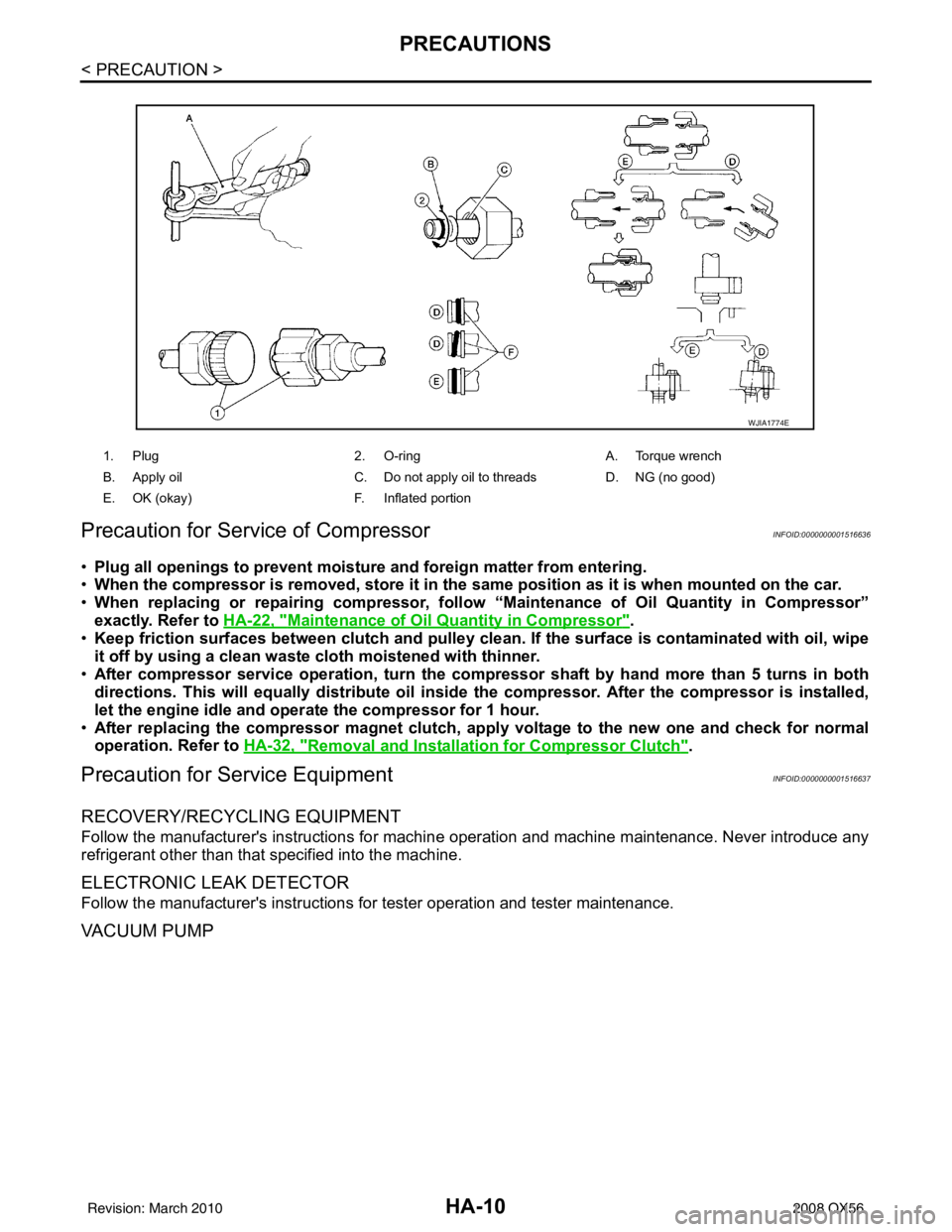
1. Plug 2. O-ring A. Torque wrench
B. Apply oil C. Do not apply oil to threads D. NG (no good)
E. OK (okay) F. Inflated portion
WJIA1774E
Revision: March 2010 2008 QX56
Page 2227 of 4083

HA-22
< ON-VEHICLE MAINTENANCE >
OIL
OIL
Maintenance of Oil Quantity in CompressorINFOID:0000000001516645
The oil in the compressor circulates through the system with the refrigerant. Add oil to compressor when
replacing any component or after a large refrigerant leakage has occurred. It is important to maintain the spec-
ified amount.
If oil quantity is not maintained properly, the following malfunctions may result:
• Lack of oil: May lead to a seized compressor
• Excessive oil: Inadequate cooling (thermal exchange interference)
OIL
Name: NISSAN A/C System Oil Type S or equivalent
CHECKING AND ADJUSTING
CAUTION:
If excessive oil leakage is noted, do not perform the oil return operation.
Start the engine and set the following conditions:
Test Condition
• Engine speed: Idling to 1,200 rpm
• A/C switch: On
• Blower fan speed: MAX position
• Temp. control: Optional [Set so that intake air temperature is 25 ° to 30 ° C (77 ° to 86 °F)]
• Intake position: Recirculation ( )
• Perform oil return operation for about ten minutes
Adjust the oil quantity according to the following table.
Oil Adjusting Procedure for Components Replacement Except Compressor
After replacing any of the following major components, add the correct amount of oil to the system.
Amount of Oil to be Added
• *1: If refrigerant leak is small, no addition of oil is needed.
Oil Adjustment Procedure for Compressor Replacement
Part replaced Oil to be added to system
Remarks
Amount of oil
m (US fl oz, Imp fl oz)
Front evaporator 75 (2.5, 2.6)—
Rear evaporator 75 (2.5, 2.6)—
Condenser 75 (2.5, 2.6)—
Liquid tank 5 (0.2, 0.2)Add if compressor is not replaced.
In case of refrigerant leak 30 (1.0, 1.1)
Large leak
— Small leak *1
Revision: March 2010 2008 QX56
Page 2229 of 4083

HA-24
< ON-VEHICLE MAINTENANCE >
FLUORESCENT LEAK DETECTOR
FLUORESCENT LEAK DETECTOR
Checking of Refrigerant LeaksINFOID:0000000001516646
PRELIMINARY CHECK
Perform a visual inspection of all refrigeration parts, fittings, hoses and components for signs of A/C oil leak-
age, damage, and corrosion. Any A/C oil leakage may indicate an area of refrigerant leakage. Allow extra
inspection time in these areas when using either an el ectronic refrigerant leak detector (J-41995) or fluores-
cent dye leak detector (J-42220).
If any dye is observed using a fluorescent dye leak detector (J-42220), confirm the leak using a electronic
refrigerant leak detector (J-41995). It is possible that the dye is from a prior leak that was repaired and not
properly cleaned.
When searching for leaks, do not stop when one leak is found but continue to check for additional leaks at all
system components and connections.
When searching for refrigerant leaks using an electronic refrigerant leak detector (J-41995), move the probe
along the suspected leak area at 25 - 50 mm (1 - 2 in) per second and no further than 6 mm (1/4 in) from the
component.
CAUTION:
Moving the electronic refrigerant l eak detector probe slower and closer to the suspected leak area will
improve the chances of finding a leak.
Checking System for L eaks Using the Fluorescent Dye Leak DetectorINFOID:0000000001516647
1. Check the A/C system for leaks using the fluorescent dye leak detector and safety goggles (J-42220) in a
low sunlight area (area without windows preferable). Il luminate all components, fittings and lines. The dye
will appear as a bright green/yellow area at the point of leakage. Fluorescent dye observed at the evapo-
rator drain opening indicates an evaporator core asse mbly leak (tubes, core or expansion valve).
2. If the suspected area is difficult to see, use an adjustable mirror or wipe the area with a clean shop rag or cloth, then inspect the shop rag or cloth with the fl uorescent dye leak detector (J-42220) for dye residue.
3. After the leak is repaired, remove any residual dye using refrigerant dye cleaner (J-43872) to prevent
future misdiagnosis.
4. Perform a system performance check and then verify t he leak repair using a electronic refrigerant leak
detector (J-41995).
NOTE:
• Other gases in the work area or substances on the A/C components, for example, anti-freeze, wind-
shield washer fluid, solvents and oils, may falsely tri gger the leak detector. Make sure the surfaces to be
checked are clean.
• Clean with a dry cloth or blow off with shop air.
• Do not allow the sensor tip of the electronic refri gerant leak detector (J-41995) to contact with any sub-
stance. This can also cause false readings and may damage the detector.
Dye InjectionINFOID:0000000001516648
NOTE:
This procedure is only necessary when recharging the system or when the compressor has seized and must
be replaced.
1. Check the A/C system static (at rest) pressure . Pressure must be at least 345 kPa (3.52 kg/cm
2 , 50 psi).
2. Pour one bottle 7.4 cc (1/4 ounce) of the HFC-134a (R -134a) fluorescent leak detection dye (J-41447) into
the HFC-134a (R-134a) dye injector (J-41459).
CAUTION:
If repairing the A/C system or replacing a co mponent, pour the HFC-134a (R-134a) fluorescent leak
detection dye (J-41447) directly into the open system connection and proceed with the service
procedures.
3. Connect the refrigerant dye injector (J-41459) to the low-pressure service valve.
4. Start the engine and switch the A/C system ON.
5. When the A/C system is operating (compressor running), inject one bottle 7.4 cc (1/4 ounce) of HFC-134a (R-134a) fluorescent leak detection dye (J-41447) through the low-pressure service valve using HFC-
134a (R-134a) dye injector (J-41459). Refer to the manufacturer's operating instructions.
Revision: March 2010 2008 QX56
Page 2230 of 4083

FLUORESCENT LEAK DETECTORHA-25
< ON-VEHICLE MAINTENANCE >
C
DE
F
G H
J
K L
M A
B
HA
N
O P
6. With the engine still running, disconnect the HFC-134a (R -134a) dye injector (J-41459) from the low-pres-
sure service valve.
7. Operate the A/C system for a minimum of 20 minut es to mix the HFC-134a (R-134a) fluorescent leak
detection dye (J-41447) with the A/C system oil. Depending on the leak size, operating conditions and
location of the leak, it may take from minutes to days for the HFC-134a (R-134a) fluorescent leak detec-
tion dye to penetrate an A/C system leak and become visible.
Revision: March 2010 2008 QX56
Page 2232 of 4083

ELECTRICAL LEAK DETECTORHA-27
< ON-VEHICLE MAINTENANCE >
C
DE
F
G H
J
K L
M A
B
HA
N
O P
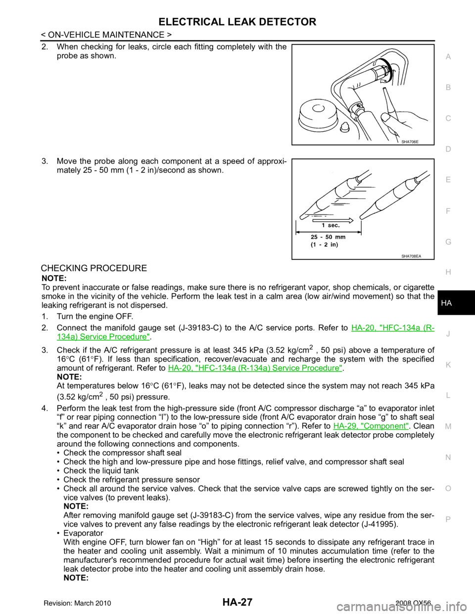
2. When checking for leaks, circle each fitting completely with the probe as shown.
3. Move the probe along each component at a speed of approxi- mately 25 - 50 mm (1 - 2 in)/second as shown.
CHECKING PROCEDURE
NOTE:
To prevent inaccurate or false readings, make sure t here is no refrigerant vapor, shop chemicals, or cigarette
smoke in the vicinity of the vehicle. Perform the leak test in a calm area (low air/wind movement) so that the
leaking refrigerant is not dispersed.
1. Turn the engine OFF.
2. Connect the manifold gauge set (J-39183-C) to the A/C service ports. Refer to HA-20, "
HFC-134a (R-
134a) Service Procedure".
3. Check if the A/C refrigerant pressu re is at least 345 kPa (3.52 kg/cm
2 , 50 psi) above a temperature of
16° C (61° F). If less than specification, recover/ev acuate and recharge the system with the specified
amount of refrigerant. Refer to HA-20, "
HFC-134a (R-134a) Service Procedure".
NOTE:
At temperatures below 16 °C (61° F), leaks may not be detected sinc e the system may not reach 345 kPa
(3.52 kg/cm
2 , 50 psi) pressure.
4. Perform the leak test from the high-pressure side (front A/C compressor discharge “a” to evaporator inlet “f” or rear piping connection “l”) to the low-pressure side (front A/C evaporator drain hose “g” to shaft seal
“k” and rear A/C evaporator drain hose “o” to piping connection “r”). Refer to HA-29, "
Component". Clean
the component to be checked and carefully move the electronic refrigerant leak detector probe completely
around the following connections and components.
• Check the compressor shaft seal
• Check the high and low-pressure pipe and hose fitt ings, relief valve, and compressor shaft seal
• Check the liquid tank
• Check the refrigerant pressure sensor
• Check all around the service valves. Check that the service valve caps are screwed tightly on the ser-
vice valves (to prevent leaks).
NOTE:
After removing manifold gauge set (J-39183-C) from the service valves, wipe any residue from the ser-
vice valves to prevent any false readings by the electronic refrigerant leak detector (J-41995).
• Evaporator
With engine OFF, turn blower fan on “High” for at least 15 seconds to dissipate any refrigerant trace in
the heater and cooling unit assembly. Wait a minimum of 10 minutes accumulation time (refer to the
manufacturer's recommended procedure for actual wait time) before inserting the electronic refrigerant
leak detector probe into the heater and cooling unit assembly drain hose.
NOTE:
SHA706E
SHA708EA
Revision: March 2010 2008 QX56
Page 2233 of 4083

HA-28
< ON-VEHICLE MAINTENANCE >
ELECTRICAL LEAK DETECTOR
Keep the probe inserted for at least 10 seconds. Use caution not to contaminate the probe tip with water
or dirt that may be in the drain hose.
5. If a leak is detected, verify at least once by blowing compressed air into the area of the suspected leak, then repeat the leak check.
6. Do not stop when one leak is found. Continue to check for additional leaks at all system components and connections.
7. If no leaks are found, perform steps 8 - 11.
8. Start the engine.
9. Set the heater A/C controls as follows: NOTE:
For the automatic system, turn OF F the automatic controls and set the heater A/C controls manually.
a. A/C switch to ON
b. Air flow to VENT mode
c. Intake position to RECIRCULATION mode
d. Temperature to MAX cold
e. Blower fan speed to HIGH
10. Run the engine at 1,500 rpm for at least 2 minutes.
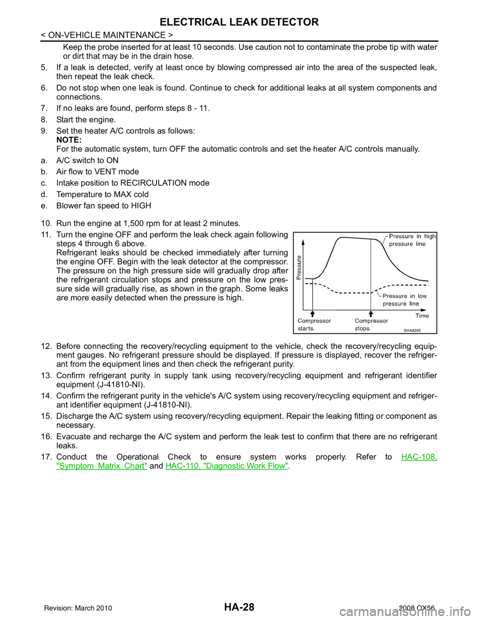
11. Turn the engine OFF and perform the leak check again following steps 4 through 6 above.
Refrigerant leaks should be checked immediately after turning
the engine OFF. Begin with the leak detector at the compressor.
The pressure on the high pressure side will gradually drop after
the refrigerant circulation stops and pressure on the low pres-
sure side will gradually rise, as shown in the graph. Some leaks
are more easily detected when the pressure is high.
12. Before connecting the recovery/recycling equipment to the vehicle, check the recovery/recycling equip-
ment gauges. No refrigerant pressure should be displayed. If pressure is displayed, recover the refriger-
ant from the equipment lines and t hen check the refrigerant purity.
13. Confirm refrigerant purity in supply tank using recovery/recycling equipment and refrigerant identifier
equipment (J-41810-NI).
14. Confirm the refrigerant purity in the vehicle's A/C system using recovery/recycling equipment and refriger-
ant identifier equipment (J-41810-NI).
15. Discharge the A/C system using recovery/recycling equipment. Repair the leaking fitting or component as
necessary.
16. Evacuate and recharge the A/C system and perform the leak test to confirm th\
at there are no refrigerant leaks.
17. Conduct the Operational Check to ensure system works properly. Refer to HAC-108,
"SymptomMatrixChart" and HAC-110, "Diagnostic Work Flow".
SHA839E
Revision: March 2010 2008 QX56
Page 2236 of 4083

COMPRESSORHA-31
< ON-VEHICLE REPAIR >
C
DE
F
G H
J
K L
M A
B
HA
N
O P
COMPRESSOR
Removal and Installation for CompressorINFOID:0000000001516652
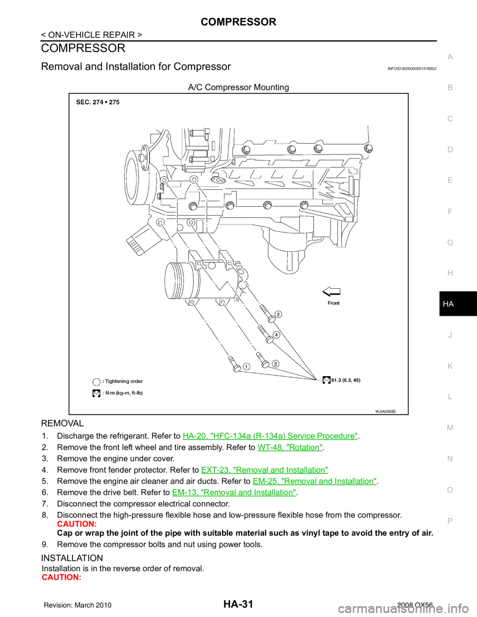
A/C Compressor Mounting
REMOVAL
1. Discharge the refrigerant. Refer to HA-20, "HFC-134a (R-134a) Service Procedure".
2. Remove the front left wheel and tire assembly. Refer to WT-48, "
Rotation".
3. Remove the engine under cover.
4. Remove front fender protector. Refer to EXT-23, "
Removal and Installation"
5. Remove the engine air cleaner and air ducts. Refer to EM-25, "Removal and Installation".
6. Remove the drive belt. Refer to EM-13, "
Removal and Installation".
7. Disconnect the compressor electrical connector.
8. Disconnect the high-pressure flexible hose and low-pressure flexible hose from the compressor. CAUTION:
Cap or wrap the joint of the pipe with suitable mate rial such as vinyl tape to avoid the entry of air.
9. Remove the compressor bolts and nut using power tools.
INSTALLATION
Installation is in the reverse order of removal.
CAUTION:
WJIA0958E
Revision: March 2010 2008 QX56