2008 INFINITI QX56 turn signal
[x] Cancel search: turn signalPage 3100 of 4083
POWER SUPPLY AND GROUND CIRCUITSCS-17
< COMPONENT DIAGNOSIS >
C
DF
G H
I
J
K L
M A
B
SCS
N
O P
POWER SUPPLY AND GROUND CIRCUIT
SUSPENSION CONTROL UNIT
SUSPENSION CONTROL UNIT : Diagnosis ProcedureINFOID:0000000001731984
1.CHECK FUSES
Check that the following fuses of the sus pension control unit are not are not blown.
Are the fuses OK?
YES >> GO TO 2
NO >> If fuse is blown, be sure to eliminate cause of malfunction before installing new fuse.
2.POWER SUPPLY CIRCUIT CHECK
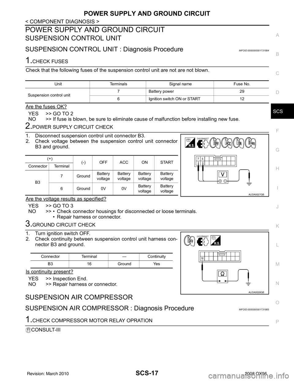
1. Disconnect suspension control unit connector B3.
2. Check voltage between the suspension control unit connector B3 and ground.
Are the voltage results as specified?
YES >> GO TO 3
NO >> • Check connector housings for disconnected or loose terminals. • Repair harness or connector.
3.GROUND CIRCUIT CHECK
1. Turn ignition switch OFF.
2. Check continuity between suspension control unit harness con- nector B3 and ground.
Is continuity present?
YES >> Inspection End.
NO >> Repair harness or connector.
SUSPENSION AIR COMPRESSOR
SUSPENSION AIR COMPRESSOR : Diagnosis ProcedureINFOID:0000000001731985
1.CHECK COMPRESSOR MOTOR RELAY OPRATION
CONSULT-III
Unit Terminals Signal name Fuse No.
Suspension control unit 7
Battery power 29
6 Ignition switch ON or START 12
(+)
(-) OFF ACC ON START
Connector Terminal
B3 7Ground
Battery
voltage Battery
voltage Battery
voltage Battery
voltage
6Ground0V 0V Battery
voltage Battery
voltage
ALEIA0027GB
Connector Terminal —Continuity
B3 16Ground Yes
ALEIA0028GB
Revision: March 2010 2008 QX56
Page 3103 of 4083
SCS-20
< COMPONENT DIAGNOSIS >
COMPRESSOR MOTOR RELAY
COMPRESSOR MOTOR RELAY
DescriptionINFOID:0000000001731987
Receives suspension air compressor ON signal from suspension control unit. When activated, the compressor
motor relay supplies power to the suspension air compressor.
Component Function CheckINFOID:0000000001731988
1.CHECK COMPRESSOR MOTOR RELAY OPERATION
CAUTION:
The "COMPRESSOR" active test will remain ON until it is turned off using CONSULT-III. Allowing the
compressor to run for an extended period of time may cause damage to the suspension control sys-
tem components due to excessive air pressure.
CONSULT-III
1. Turn ignition ON.
2. Select "COMPRESSOR" of AIR LEVELIZER active test items.
3. While operating test item, check that the suspension air compressor turns ON.
Does the suspension air compressor operate properly?
YES >> Compressor motor relay and suspension air compressor are operating normally.
NO >> Refer to SCS-20, "
Diagnosis Procedure"
Diagnosis ProcedureINFOID:0000000001731989
1.CHECK COMPRESSOR "ON" SIGNAL FROM SUSPENSION CONTROL UNIT
CONSULT-III
1. Turn ignition switch ON.
2. Disconnect compressor motor relay connector E130.
3. Select "COMPRESSOR" of AIR LEVELIZER active test items.
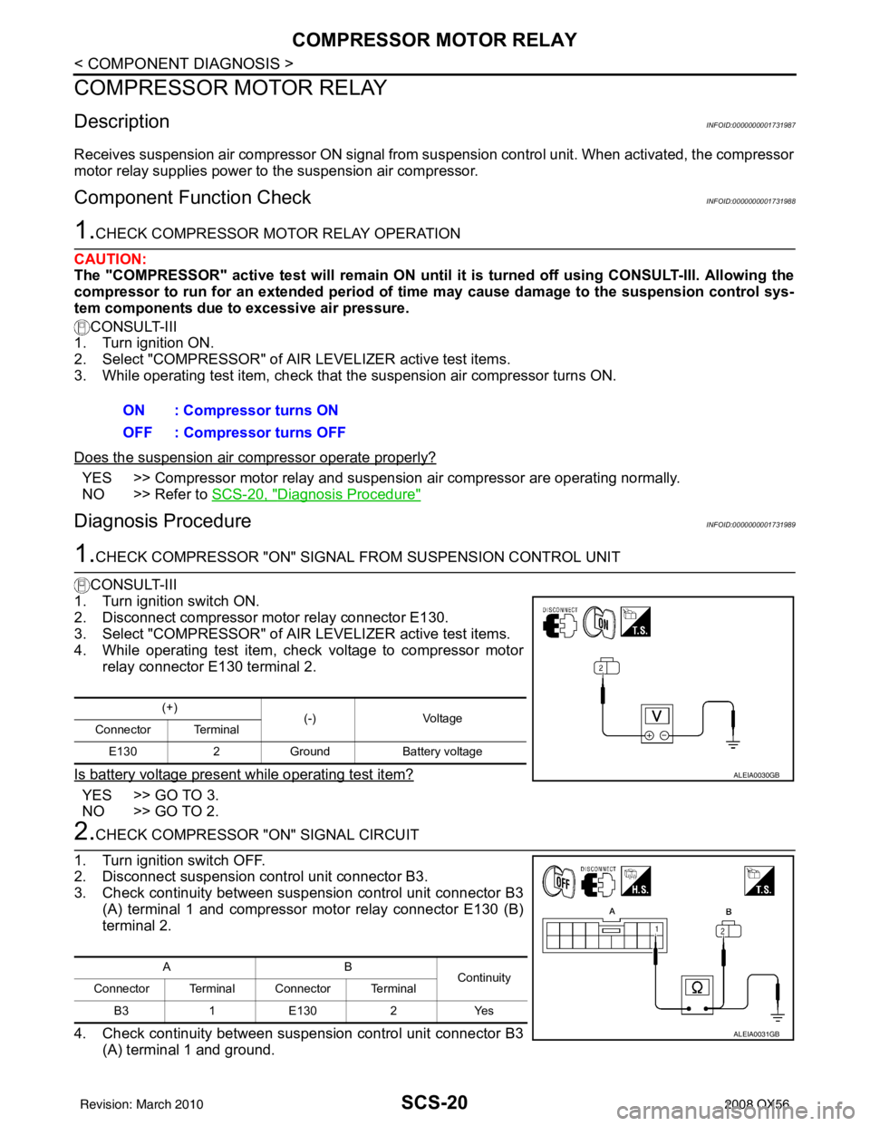
4. While operating test item, check voltage to compressor motor relay connector E130 terminal 2.
Is battery voltage present while operating test item?
YES >> GO TO 3.
NO >> GO TO 2.
2.CHECK COMPRESSOR "ON" SIGNAL CIRCUIT
1. Turn ignition switch OFF.
2. Disconnect suspension control unit connector B3.
3. Check continuity between suspension control unit connector B3 (A) terminal 1 and compressor motor relay connector E130 (B)
terminal 2.
4. Check continuity between suspension control unit connector B3 (A) terminal 1 and ground.ON : Compressor turns ON
OFF : Compressor turns OFF
(+)
(-)Voltage
Connector Terminal
E130 2Ground Battery voltage
ALEIA0030GB
AB
Continuity
Connector Terminal Connector Terminal
B3 1E 1302 Y es
ALEIA0031GB
Revision: March 2010 2008 QX56
Page 3106 of 4083
EXHAUST VALVE SOLENOID CIRCUITSCS-23
< COMPONENT DIAGNOSIS >
C
DF
G H
I
J
K L
M A
B
SCS
N
O P
EXHAUST VALVE SOLENOID CIRCUIT
DescriptionINFOID:0000000001731993
Receives exhaust valve solenoid signal from suspension control unit. When activated, the exhaust valve sole-
noid releases air pressure from the suspension control system.
Component Function CheckINFOID:0000000001731994
1.CHECK EXHAUST SOLENOID OPERATION
CAUTION:
While operating this active test, the suspension control system wil l vent air pressure and the vehicle
ride height will lower. Ensure th e area around the vehicle is free from obstructions before beginning
test.
CONSULT-III
1. Ensure the suspension control system has air pressure and is not drooping in the rear.
2. Select "EXHAUST SOLENOID" of AIR LEVELIZER active test items.
3. While operating test item, check that the exhaust va lve solenoid opens to vent air from the system. The
vehicle should lower when the exhaust valve solenoid is activated.
Does the system vent properly?
YES >> Exhaust valve solenoid is operating normally.
NO >> Refer to SCS-23, "
Diagnosis Procedure"
Diagnosis ProcedureINFOID:0000000001731995
1.CHECK EXHAUST VALVE SOLENOID SIGNAL
CONSULT-III
1. Connect suspension control unit connector B3.
2. Turn ignition switch ON.
3. Select "EXHAUST SOLENOID" of AIR LEVELIZER active test
items.
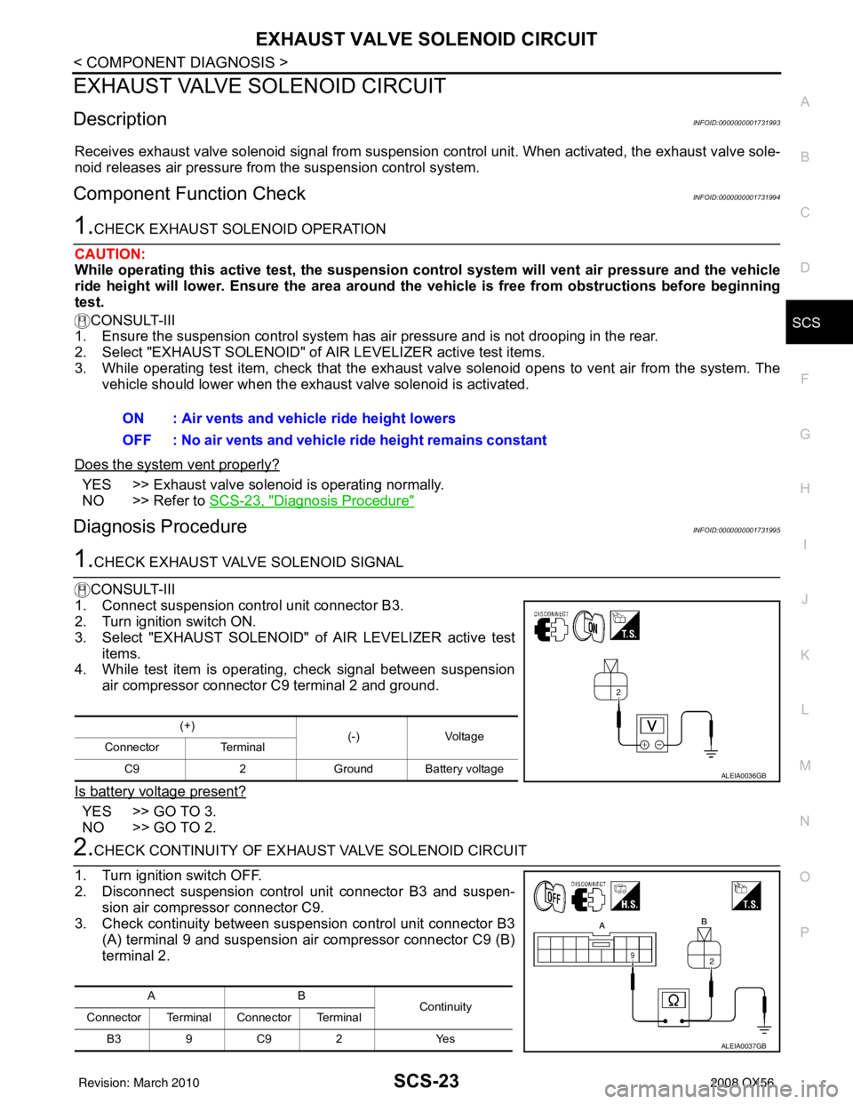
4. While test item is operating, check signal between suspension
air compressor connector C9 terminal 2 and ground.
Is battery voltage present?
YES >> GO TO 3.
NO >> GO TO 2.
2.CHECK CONTINUITY OF EXHAU ST VALVE SOLENOID CIRCUIT
1. Turn ignition switch OFF.
2. Disconnect suspension control unit connector B3 and suspen- sion air compressor connector C9.
3. Check continuity between suspension control unit connector B3
(A) terminal 9 and suspension air compressor connector C9 (B)
terminal 2.ON : Air vents and vehicle ride height lowers
OFF : No air vents and vehicle ride height remains constant
(+)
(-)Voltage
Connector Terminal
C9 2Ground Battery voltage
ALEIA0036GB
AB
Continuity
Connector Terminal Connector Terminal
B39C 92 Y es
ALEIA0037GB
Revision: March 2010 2008 QX56
Page 3108 of 4083
CK SUSP WARNING INDICATOR CONTROL CIRCUITSCS-25
< COMPONENT DIAGNOSIS >
C
DF
G H
I
J
K L
M A
B
SCS
N
O P
CK SUSP WARNING INDICATOR CONTROL CIRCUIT
DescriptionINFOID:0000000001731996
The CK SUSP warning lamp is controlled by a ground signal provided to the combination meter by the sus-
pension control unit.
Component Function CheckINFOID:0000000001731997
1.CHECK WARNING LAMP OPERATION
CONSULT-III
1. Turn ignition ON.
2. Select "WARNING LAMP" of AI R LEVELIZER active test items.
3. While operating test item, check that the warning lamp activates.
Does the warning lamp operate properly?
YES >> Warning lamp is operating normally.
NO >> Refer to SCS-25, "
Diagnosis Procedure"
Diagnosis ProcedureINFOID:0000000001731998
1.PERFORM SUSPENSION CONTROL SYSTEM SELF-DIAGNOSIS
CONSULT-III
1. Turn ignition ON.
2. Perform SELF DIAGNOSIS function of AIR LEVELIZER system.
Are any DTC's present?
YES >> Refer to SCS-33, "DTC Index"
NO >> • If warning lamp is always ON, GO TO 2.
• If warning lamp is always OFF, GO TO 3
2.CHECK SUSPENSION CONTROL UNIT WARNING LAMP CONTROL
1. Turn ignition OFF.
2. Disconnect the suspension control unit connector B3.
3. Turn ignition ON.
Does the CK SUSP warning lamp turn ON?
YES >> GO TO 3.
NO >> Replace the suspension control unit. Refer to RSU-25, "
Removal and Installation"
3.CHECK CONTINUITY OF WARNING LAMP CONTROL CIRCUIT
1. Turn ignition switch OFF.
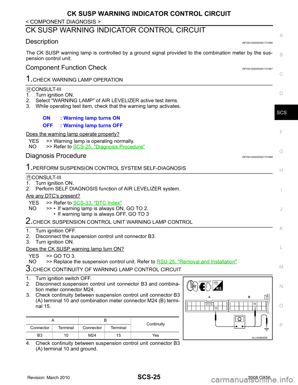
2. Disconnect suspension control unit connector B3 and combina- tion meter connector M24.
3. Check continuity between suspension control unit connector B3 (A) terminal 10 and combination meter connector M24 (B) termi-
nal 15.
4. Check continuity between suspension control unit connector B3 (A) terminal 10 and ground.ON : Warning lamp turns ON
OFF : Warning lamp turns OFF
AB
Continuity
Connector Terminal Connector Terminal
B3 10 M24 15 Yes
ALLIA0693GB
Revision: March 2010 2008 QX56
Page 3119 of 4083
SCS-36
< SYMPTOM DIAGNOSIS >
SUSPENSION CONTROL SYSTEM INOPERATIVE
SUSPENSION CONTROL SYSTEM INOPERATIVE
DescriptionINFOID:0000000001732003
The suspension control system does not activate. It does not raise or lower the vehicle in response to ride
height changes.
Diagnosis ProcedureINFOID:0000000001732004
1.SUSPENSION CONTROL UNIT PO WER AND GROUND INSPECTION
Check the suspension control unit power and ground supply. Refer to SCS-17, "
SUSPENSION CONTROL
UNIT : Diagnosis Procedure".
Does the suspension control unit power and ground pass inspection?
YES >> GO TO 2
NO >> Repair or replace the malfunctioning part.
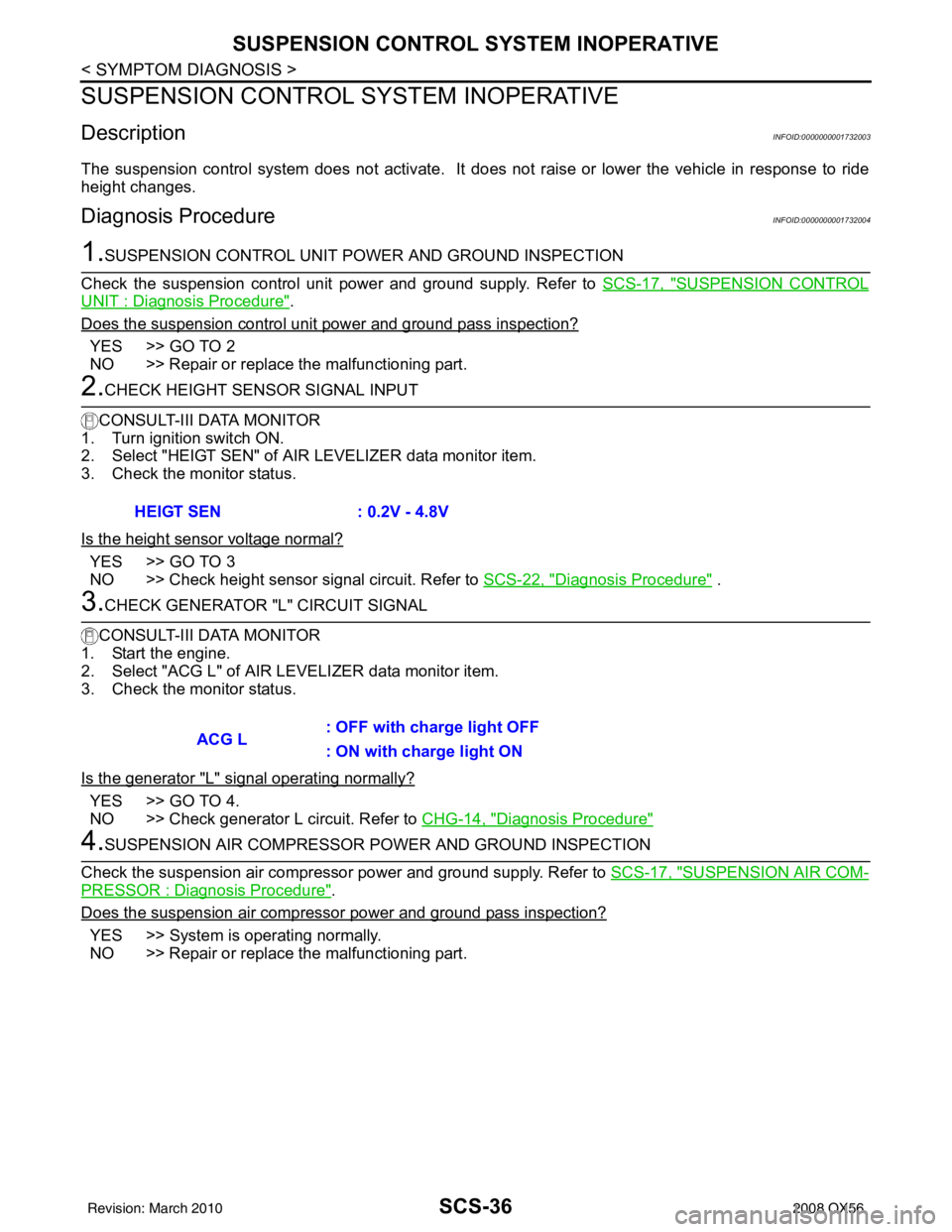
2.CHECK HEIGHT SENSOR SIGNAL INPUT
CONSULT-III DATA MONITOR
1. Turn ignition switch ON.
2. Select "HEIGT SEN" of AI R LEVELIZER data monitor item.
3. Check the monitor status.
Is the height sensor voltage normal?
YES >> GO TO 3
NO >> Check height sensor signal circuit. Refer to SCS-22, "
Diagnosis Procedure" .
3.CHECK GENERATOR "L" CIRCUIT SIGNAL
CONSULT-III DATA MONITOR
1. Start the engine.
2. Select "ACG L" of AIR LE VELIZER data monitor item.
3. Check the monitor status.
Is the generator "L" signal operating normally?
YES >> GO TO 4.
NO >> Check generator L circuit. Refer to CHG-14, "
Diagnosis Procedure"
4.SUSPENSION AIR COMPRESSOR POWER AND GROUND INSPECTION
Check the suspension air compressor power and ground supply. Refer to SCS-17, "
SUSPENSION AIR COM-
PRESSOR : Diagnosis Procedure".
Does the suspension air compressor power and ground pass inspection?
YES >> System is operating normally.
NO >> Repair or replace the malfunctioning part. HEIGT SEN
: 0.2V - 4.8V
ACG L: OFF with charge light OFF
: ON with charge light ON
Revision: March 2010
2008 QX56
Page 3120 of 4083
SUSPENSION CONTROL SYSTEM DOES NOT RAISE
SCS-37
< SYMPTOM DIAGNOSIS >
C
D F
G H
I
J
K L
M A
B
SCS
N
O P
SUSPENSION CONTROL SYST EM DOES NOT RAISE
DescriptionINFOID:0000000001732005
The suspension control system does not raise the vehicle in accordance with ride height changes.
Diagnosis ProcedureINFOID:0000000001732006
1.SUSPENSION CONTROL UNIT PO WER AND GROUND INSPECTION
Check the suspension control unit power and ground supply. Refer to SCS-17, "
SUSPENSION CONTROL
UNIT : Diagnosis Procedure".
Does the suspension control uni t power and ground pass inspection?
YES >> GO TO 2
NO >> Repair or replace the malfunctioning part.
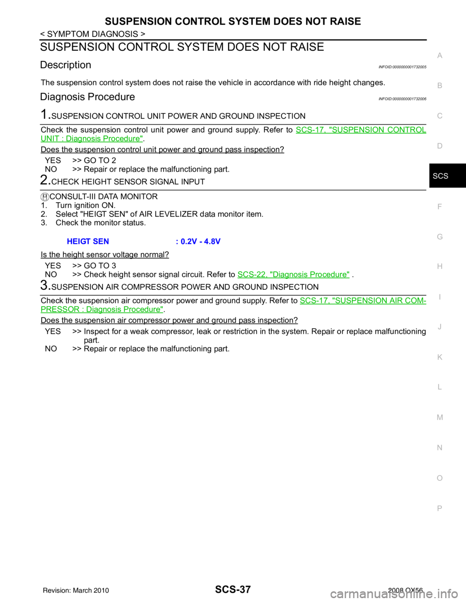
2.CHECK HEIGHT SENSOR SIGNAL INPUT
CONSULT-III DATA MONITOR
1. Turn ignition ON.
2. Select "HEIGT SEN" of AI R LEVELIZER data monitor item.
3. Check the monitor status.
Is the height sensor voltage normal?
YES >> GO TO 3
NO >> Check height sensor signal circuit. Refer to SCS-22, "
Diagnosis Procedure" .
3.SUSPENSION AIR COMPRESSOR POWER AND GROUND INSPECTION
Check the suspension air compressor power and ground supply. Refer to SCS-17, "
SUSPENSION AIR COM-
PRESSOR : Diagnosis Procedure".
Does the suspension air compress or power and ground pass inspection?
YES >> Inspect for a weak compressor, leak or restriction in the system. Repair or replace malfunctioning
part.
NO >> Repair or replace the malfunctioning part. HEIGT SEN
: 0.2V - 4.8V
Revision: March 2010 2008 QX56
Page 3121 of 4083
SCS-38
< SYMPTOM DIAGNOSIS >
SUSPENSION CONTROL SYSTEM DOES NOT LOWER
SUSPENSION CONTROL SYSTEM DOES NOT LOWER
DescriptionINFOID:0000000001732007
The suspension control system does not lower the vehicle in accordance with ride height changes.
Diagnosis ProcedureINFOID:0000000001732008
1.SUSPENSION CONTROL UNIT PO WER AND GROUND INSPECTION
Check the suspension control unit power and ground supply. Refer to SCS-17, "
SUSPENSION CONTROL
UNIT : Diagnosis Procedure".
Does the suspension control unit power and ground pass inspection?
YES >> GO TO 2
NO >> Repair or replace the malfunctioning part.
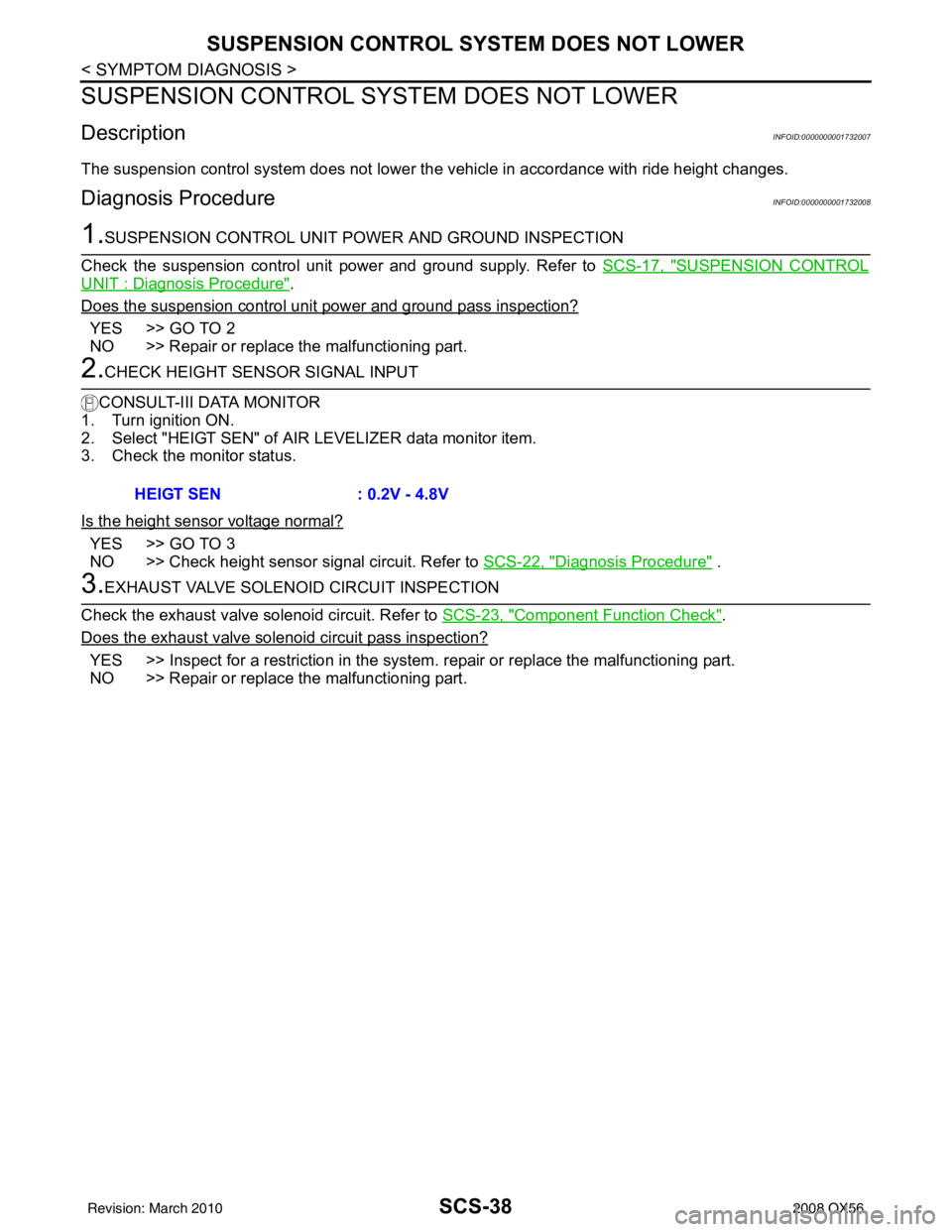
2.CHECK HEIGHT SENSOR SIGNAL INPUT
CONSULT-III DATA MONITOR
1. Turn ignition ON.
2. Select "HEIGT SEN" of AI R LEVELIZER data monitor item.
3. Check the monitor status.
Is the height sensor voltage normal?
YES >> GO TO 3
NO >> Check height sensor signal circuit. Refer to SCS-22, "
Diagnosis Procedure" .
3.EXHAUST VALVE SOLENOID CIRCUIT INSPECTION
Check the exhaust valve solenoid circuit. Refer to SCS-23, "
Component Function Check".
Does the exhaust valve solenoid circuit pass inspection?
YES >> Inspect for a restriction in the system . repair or replace the malfunctioning part.
NO >> Repair or replace the malfunctioning part. HEIGT SEN
: 0.2V - 4.8V
Revision: March 2010 2008 QX56
Page 3128 of 4083
SE-6
< FUNCTION DIAGNOSIS >
THIRD ROW POWER FOLDING SEAT
FUNCTION DIAGNOSIS
THIRD ROW POWER FOLDING SEAT
System DescriptionINFOID:0000000001735711
The third row power folding seat system is capable of allowing a user to fold up or down either the left or right
third row seat using a set of front or rear mounted switches.
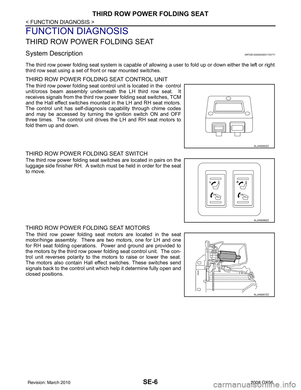
THIRD ROW POWER FOLDIN G SEAT CONTROL UNIT
The third row power folding seat control unit is located in the control
unit/cross beam assembly underneath the LH third row seat. It
receives signals from the third row power folding seat switches, TCM
and the Hall effect switches mounted in the LH and RH seat motors.
The control unit has self-diagnosis capability through chime codes
and may be accessed by turning the ignition switch ON and OFF
three times. The control unit drives the LH and RH seat motors to
fold them up and down.
THIRD ROW POWER FOLDING SEAT SWITCH
The third row power folding seat switches are located in pairs on the
luggage side finisher RH. A switch must be held in order for the seat
to move.
THIRD ROW POWER FOLDING SEAT MOTORS
The third row power folding seat motors are located in the seat
motor/hinge assembly. There are two motors, one for LH and one
for RH seat folding operations. Power and ground are provided to
the motors by the third row power fo lding seat control unit. The con-
trol unit reverses polarity to the motors to raise or lower the seat.
The motors also contain Hall effe ct switches. These switches send
signals back to the control unit which help it determine fully open and
closed positions.
ALJIA0085ZZ
ALJIA0086ZZ
ALJIA0087ZZ
Revision: March 2010 2008 QX56