2008 INFINITI QX56 turn signal
[x] Cancel search: turn signalPage 3005 of 4083
BCM (BODY CONTROL MODULE)RF-21
< ECU DIAGNOSIS >
C
DE
F
G H
I
J
L
M A
B
RF
N
O P
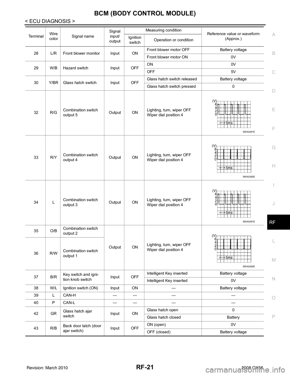
28 L/R Front blower monitor Input ON Front blower motor OFF Battery voltage
Front blower motor ON
0V
29 W/B Hazard switch Input OFFON
0V
OFF 5V
30 Y/BR Glass hatch switch Input OFF Glass hatch switch released
Battery voltage
Glass hatch switch pressed 0
32 R/G Combination switch
output 5
Output ONLighting, turn, wiper OFF
Wiper dial position 4
33 R/Y Combination switch
output 4 Output ONLighting, turn, wiper OFF
Wiper dial position 4
34 L Combination switch
output 3 Output ON
Lighting, turn, wiper OFF
Wiper dial position 4
35 O/B Combination switch
output 2
Output ONLighting, turn, wiper OFF
Wiper dial position 4
36 R/W Combination switch
output 1
37 B/R Key switch and igni-
tion knob switch Input OFFIntelligent Key inserted
Battery voltage
Intelligent Key inserted 0V
38 W/L Ignition switch (ON) Input ON —Battery voltage
39 L CAN-H — —— —
40 P CAN-L — —— —
42 GR Glass hatch ajar
switch Input ONGlass hatch open
0
Glass hatch closed Battery
43 R/B Back door latch (door
ajar switch) Input OFFON (open)
0V
OFF (closed) Battery voltage
Te r m i n a l
Wire
color Signal name Signal
input/
output Measuring condition
Reference value or waveform
(Approx.)
Ignition
switch Operation or condition
SKIA5291E
SKIA5292E
SKIA5291E
SKIA5292E
Revision: March 2010
2008 QX56
Page 3006 of 4083
RF-22
< ECU DIAGNOSIS >
BCM (BODY CONTROL MODULE)
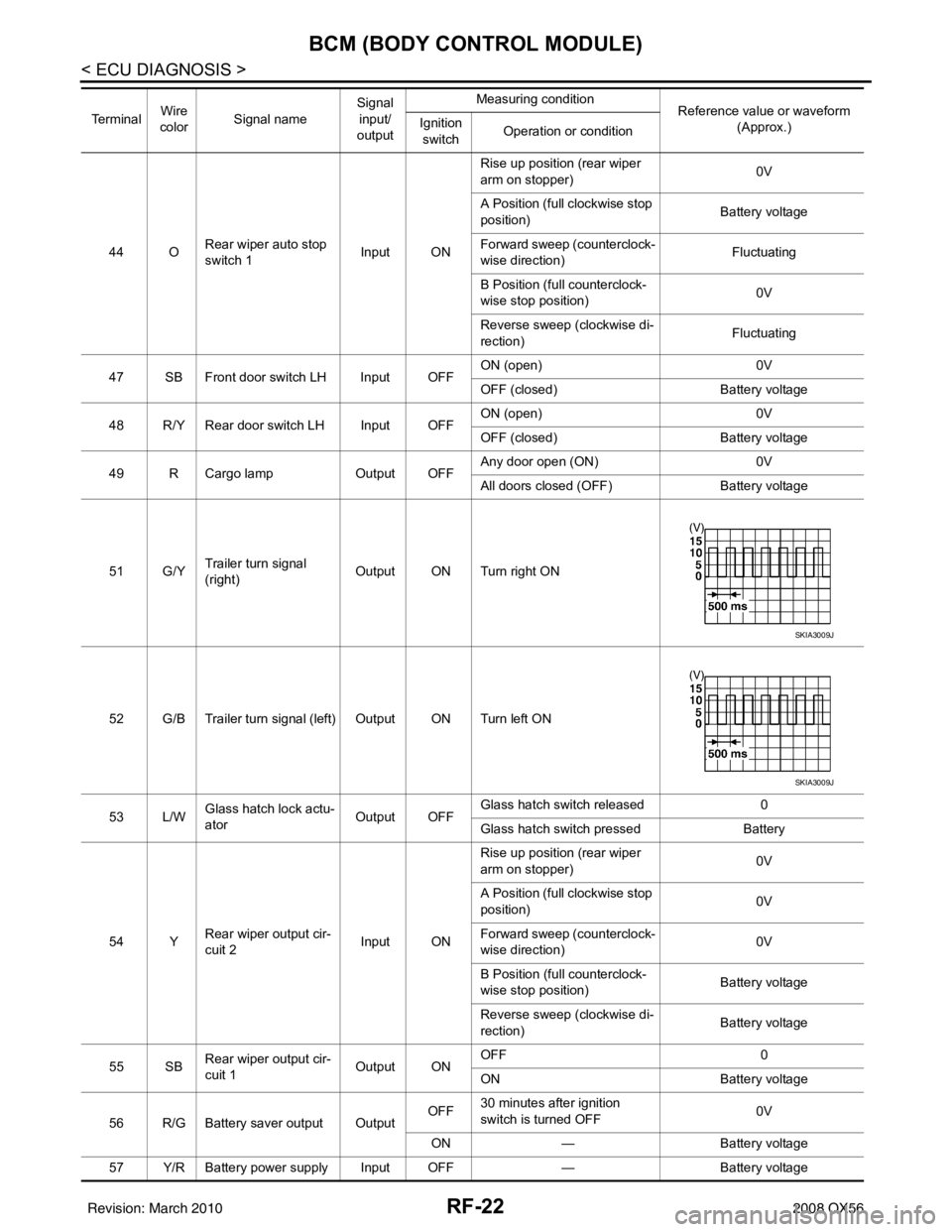
44 ORear wiper auto stop
switch 1 Input ONRise up position (rear wiper
arm on stopper)
0V
A Position (full clockwise stop
position) Battery voltage
Forward sweep (counterclock-
wise direction) Fluctuating
B Position (full counterclock-
wise stop position) 0V
Reverse sweep (clockwise di-
rection) Fluctuating
47 SB Front door switch LH Input OFF ON (open)
0V
OFF (closed) Battery voltage
48 R/Y Rear door switch LH Input OFF ON (open)
0V
OFF (closed) Battery voltage
49 R Cargo lamp Output OFFAny door open (ON)
0V
All doors closed (OFF) Battery voltage
51 G/Y Trailer turn signal
(right) Output ON Turn right ON
52 G/B Trailer turn signal (l eft) Output ON Turn left ON
53 L/W Glass hatch lock actu-
ator
Output OFFGlass hatch switch released
0
Glass hatch switch pressed Battery
54 Y Rear wiper output cir-
cuit 2 Input ONRise up position (rear wiper
arm on stopper)
0V
A Position (full clockwise stop
position) 0V
Forward sweep (counterclock-
wise direction) 0V
B Position (full counterclock-
wise stop position) Battery voltage
Reverse sweep (clockwise di-
rection) Battery voltage
55 SB Rear wiper output cir-
cuit 1 Output ONOFF
0
ON Battery voltage
56 R/G Battery saver output Output OFF
30 minutes after ignition
switch is turned OFF 0V
ON — Battery voltage
57 Y/R Battery power supply Input OFF —Battery voltage
Te r m i n a l
Wire
color Signal name Signal
input/
output Measuring condition
Reference value or waveform
(Approx.)
Ignition
switch Operation or condition
SKIA3009J
SKIA3009J
Revision: March 2010
2008 QX56
Page 3007 of 4083
BCM (BODY CONTROL MODULE)RF-23
< ECU DIAGNOSIS >
C
DE
F
G H
I
J
L
M A
B
RF
N
O P
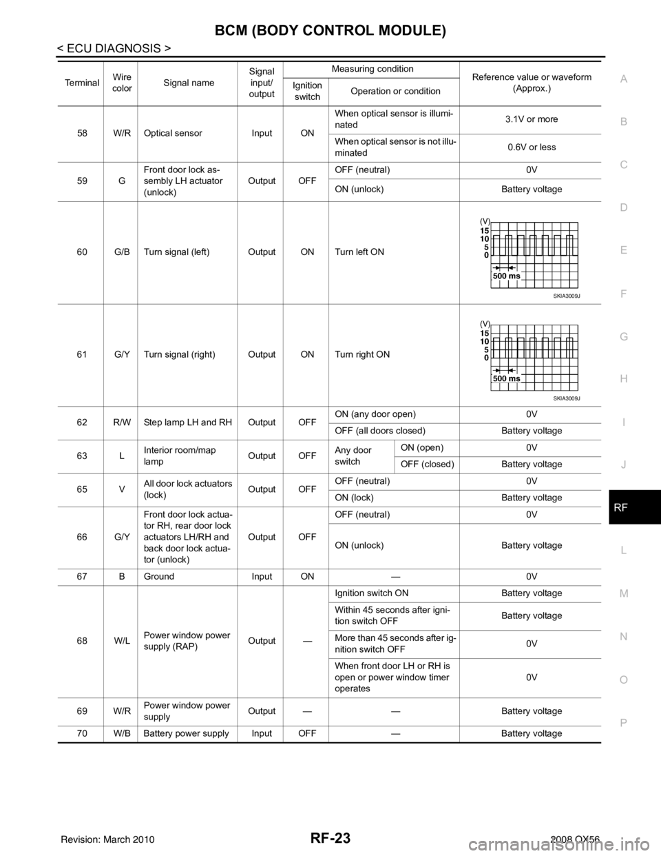
58 W/R Optical sensor Input ONWhen optical sensor is illumi-
nated
3.1V or more
When optical sensor is not illu-
minated 0.6V or less
59 G Front door lock as-
sembly LH actuator
(unlock) Output OFF
OFF (neutral)
0V
ON (unlock) Battery voltage
60 G/B Turn signal (left) Output ON Turn left ON
61 G/Y Turn signal (right) Output ON Turn right ON
62 R/W Step lamp LH and RH Output OFF ON (any door open)
0V
OFF (all doors closed) Battery voltage
63 L Interior room/map
lamp Output OFFAny door
switchON (open)
0V
OFF (closed) Battery voltage
65 V All door lock actuators
(lock) Output OFFOFF (neutral)
0V
ON (lock) Battery voltage
66 G/Y Front door lock actua-
tor RH, rear door lock
actuators LH/RH and
back door lock actua-
tor (unlock) Output OFF
OFF (neutral)
0V
ON (unlock) Battery voltage
67 B Ground Input ON—0V
68 W/L Power window power
supply (RAP) Output —Ignition switch ON
Battery voltage
Within 45 seconds after igni-
tion switch OFF Battery voltage
More than 45 seconds after ig-
nition switch OFF 0V
When front door LH or RH is
open or power window timer
operates 0V
69 W/R Power window power
supply
Output —
—Battery voltage
70 W/B Battery power supply Input OFF —Battery voltage
Te r m i n a l
Wire
color Signal name Signal
input/
output Measuring condition
Reference value or waveform
(Approx.)
Ignition
switch Operation or condition
SKIA3009J
SKIA3009J
Revision: March 2010
2008 QX56
Page 3012 of 4083

RF-28
< ECU DIAGNOSIS >
BCM (BODY CONTROL MODULE)
DTC Inspection Priority Chart
INFOID:0000000004874890
If some DTCs are displayed at the same time, perform inspections one by one based on the following priority
chart.
DTC IndexINFOID:0000000004874891
NOTE: Details of time display
• CRNT: Displays when there is a malfunction now or after returning to the normal condition until turning igni-
tion switch OFF → ON again.
• 1 - 39: Displayed if any previous malfunction is present when current condition is normal. It increases like 1
→ 2 → 3...38 → 39 after returning to the normal condition whenever ignition switch OFF → ON. The counter
remains at 39 even if the number of cycles exceeds it. It is counted from 1 again when turning ignition switch
OFF → ON after returning to the normal condition if the malfunction is detected again.
Display contents of CONS ULTFail-safe Cancellation
U1000: CAN COMM CIRCUIT I nhibit engine crankingWhen the BCM re-establishes communication with the other mod-
ules.
U1010: CONTROL UNIT (CAN) Inhibit engine cranking When the BCM re-start communicating with the other modules.
Priority DTC
1 • U1000: CAN COMM CIRCUIT
• U1010: CONTROL UNIT (CAN)
2 • B2190: NATS ANTENNA AMP
• B2191: DIFFERENCE OF KEY
• B2192: ID DISCORD BCM-ECM
• B2193: CHAIN OF BCM-ECM
• B2013: STRG COMM 1
• B2552: INTELLIGENT KEY
• B2590: NATS MALFUNCTION
3 • C1729: VHCL SPEED SIG ERR
• C1735: IGNITION SIGNAL
4 • C1704: LOW PRESSURE FL
• C1705: LOW PRESSURE FR
• C1706: LOW PRESSURE RR
• C1707: LOW PRESSURE RL
• C1708: [NO DATA] FL
• C1709: [NO DATA] FR
• C1710: [NO DATA] RR
• C1711: [NO DATA] RL
• C1712: [CHECKSUM ERR] FL
• C1713: [CHECKSUM ERR] FR
• C1714: [CHECKSUM ERR] RR
• C1715: [CHECKSUM ERR] RL
• C1716: [PRESSDATA ERR] FL
• C1717: [PRESSDATA ERR] FR
• C1718: [PRESSDATA ERR] RR
• C1719: [PRESSDATA ERR] RL
• C1720: [CODE ERR] FL
• C1721: [CODE ERR] FR
• C1722: [CODE ERR] RR
• C1723: [CODE ERR] RL
• C1724: [BATT VOLT LOW] FL
• C1725: [BATT VOLT LOW] FR
• C1726: [BATT VOLT LOW] RR
• C1727: [BATT VOLT LOW] RL
Revision: March 2010
2008 QX56
Page 3014 of 4083
RF-30
< ECU DIAGNOSIS >
SUNROOF SYSTEM
SUNROOF SYSTEM
Reference ValueINFOID:0000000001731937
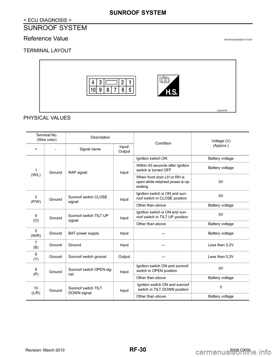
TERMINAL LAYOUT
PHYSICAL VALUES
LIIA2447E
Te r m i n a l N o .(Wire color) Description
ConditionVoltage (V)
(Approx.)
+ - Signal nameInput/
Output
1
(W/L) Ground RAP signal
InputIgnition switch ON
Battery voltage
Within 45 seconds after ignition
switch is turned OFF Battery voltage
When front door LH or RH is
open while retained power is op-
erating 0V
3
(P/W) Ground Sunroof switch CLOSE
signal InputIgnition switch is ON and sun-
roof switch in CLOSE position
0V
Other than above Battery voltage
4
(O) Ground Sunroof switch TILT UP
signal
InputIgnition switch is ON and sun-
roof switch in TILT UP position
0V
Other than above Battery voltage
5
(W/R) Ground BAT power supply
Input— Battery voltage
7
(B) Ground Ground
Input— Less than 0.2V
8
(Y) Ground Sunroof switch ground Output
—Less than 0.2V
9
(P) Ground
Sunroof switch OPEN sig-
nal InputIgnition switch ON and sunroof
switch in OPEN position
0V
Other than above Battery voltage
10
(L/R) Ground Sunroof switch TILT
DOWN signal InputIgnition switch ON and sunroof
switch in TILT DOWN position 0
Other than above Battery voltage
Revision: March 2010 2008 QX56
Page 3092 of 4083
C1801 VEHICLE HEIGHT SENSORSCS-9
< COMPONENT DIAGNOSIS >
C
DF
G H
I
J
K L
M A
B
SCS
N
O P
COMPONENT DIAGNOSIS
C1801 VEHICLE HEIGHT SENSOR
DescriptionINFOID:0000000001731960
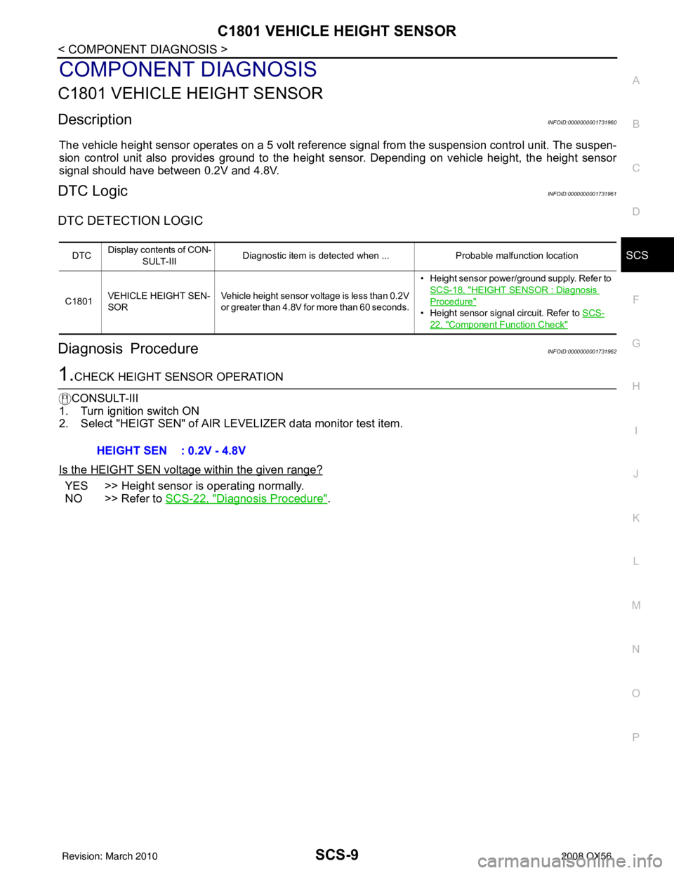
The vehicle height sensor operates on a 5 volt referenc e signal from the suspension control unit. The suspen-
sion control unit also provides ground to the height sensor. Depending on vehicle height, the height sensor
signal should have between 0.2V and 4.8V.
DTC LogicINFOID:0000000001731961
DTC DETECTION LOGIC
Diagnosis ProcedureINFOID:0000000001731962
1.CHECK HEIGHT SENSOR OPERATION
CONSULT-III
1. Turn ignition switch ON
2. Select "HEIGT SEN" of AIR L EVELIZER data monitor test item.
Is the HEIGHT SEN voltage within the given range?
YES >> Height sensor is operating normally.
NO >> Refer to SCS-22, "
Diagnosis Procedure".
DTCDisplay contents of CON-
SULT-III Diagnostic item is detected when ...
Probable malfunction location
C1801 VEHICLE HEIGHT SEN-
SOR Vehicle height sensor voltage is less than 0.2V
or greater than 4.8V for more than 60 seconds. • Height sensor power/ground supply. Refer to
SCS-18, "
HEIGHT SENSOR : Diagnosis
Procedure"
• Height sensor signal circuit. Refer to SCS-
22, "Component Function Check"
HEIGHT SEN : 0.2V - 4.8V
Revision: March 2010 2008 QX56
Page 3097 of 4083
SCS-14
< COMPONENT DIAGNOSIS >
C1806 VEHICLE HEIGHT SENSOR LOCKING MALFUNCTION
C1806 VEHICLE HEIGHT SENSOR LOCKING MALFUNCTION
DescriptionINFOID:0000000001731975
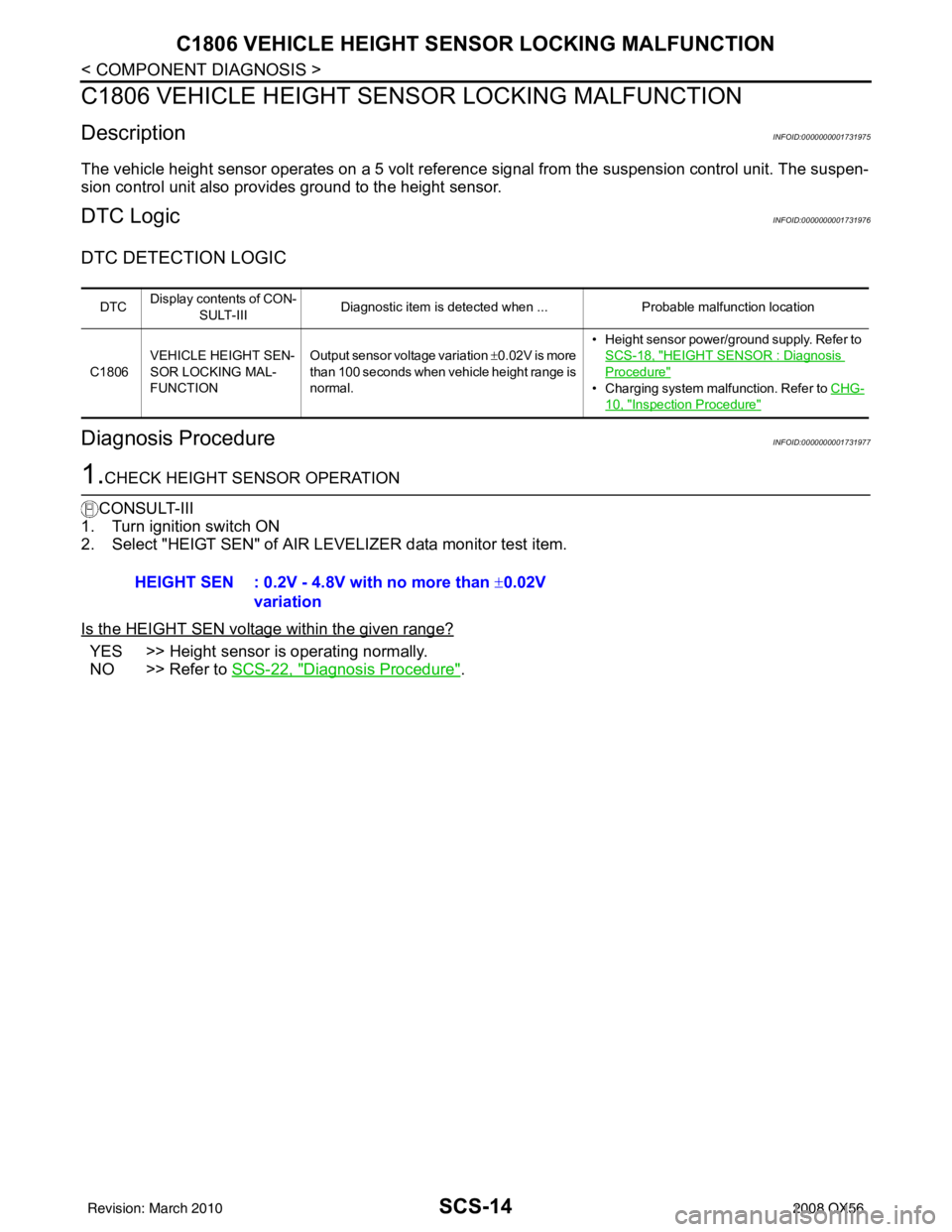
The vehicle height sensor operates on a 5 volt referenc e signal from the suspension control unit. The suspen-
sion control unit also provides ground to the height sensor.
DTC LogicINFOID:0000000001731976
DTC DETECTION LOGIC
Diagnosis ProcedureINFOID:0000000001731977
1.CHECK HEIGHT SENSOR OPERATION
CONSULT-III
1. Turn ignition switch ON
2. Select "HEIGT SEN" of AIR LEVELIZER data monitor test item.
Is the HEIGHT SEN voltage within the given range?
YES >> Height sensor is operating normally.
NO >> Refer to SCS-22, "
Diagnosis Procedure".
DTCDisplay contents of CON-
SULT-III Diagnostic item is detected when ...
Probable malfunction location
C1806 VEHICLE HEIGHT SEN-
SOR LOCKING MAL-
FUNCTION Output sensor voltage variation
±0.02V is more
than 100 seconds when vehicle height range is
normal. • Height sensor power/ground supply. Refer to
SCS-18, "
HEIGHT SENSOR : Diagnosis
Procedure"
• Charging system malfunction. Refer to CHG-
10, "Inspection Procedure"
HEIGHT SEN : 0.2V - 4.8V with no more than ± 0.02V
variation
Revision: March 2010 2008 QX56
Page 3098 of 4083
C1807 SENSOR 5V MALFUNCTIONSCS-15
< COMPONENT DIAGNOSIS >
C
DF
G H
I
J
K L
M A
B
SCS
N
O P
C1807 SENSOR 5V MALFUNCTION
DescriptionINFOID:0000000001731978
The vehicle height sensor operates on a 5 volt referenc e signal from the suspension control unit. The suspen-
sion control unit also provides ground to the height sensor.
DTC LogicINFOID:0000000001731979
DTC DETECTION LOGIC
Diagnosis ProcedureINFOID:0000000001731980
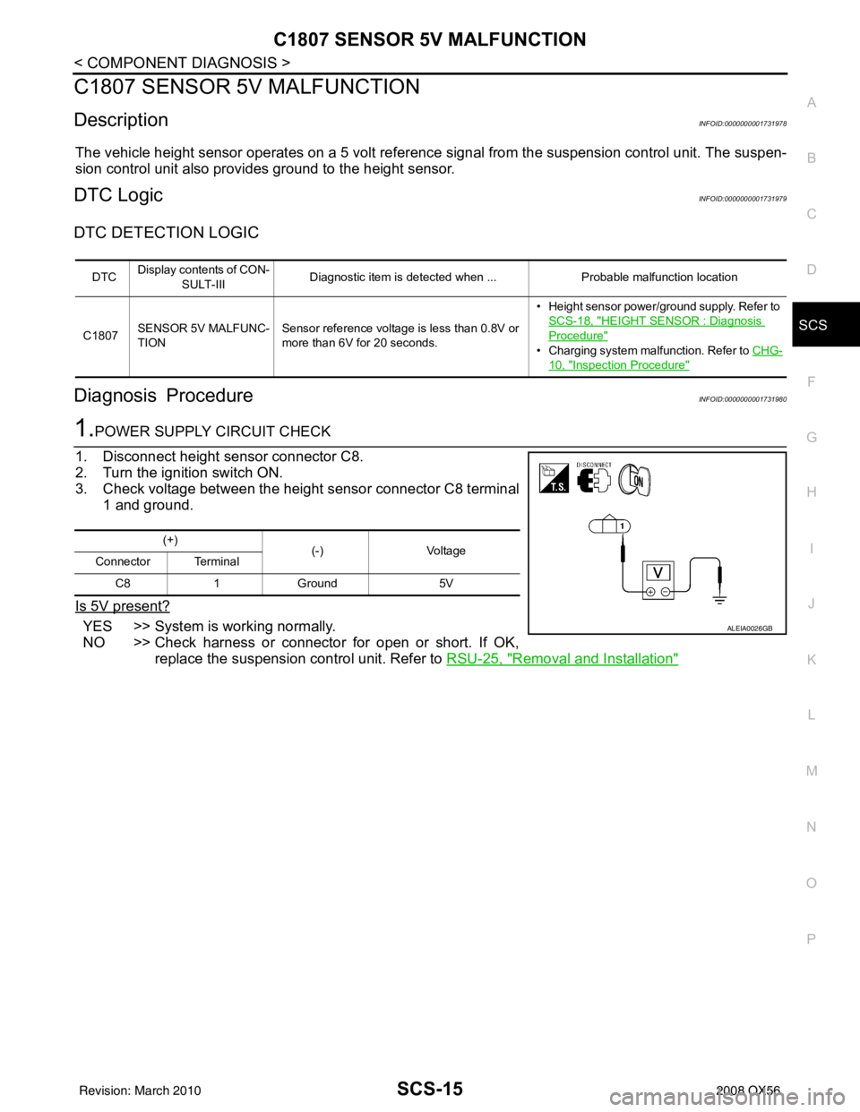
1.POWER SUPPLY CIRCUIT CHECK
1. Disconnect height sensor connector C8.
2. Turn the ignition switch ON.
3. Check voltage between the height sensor connector C8 terminal 1 and ground.
Is 5V present?
YES >> System is working normally.
NO >> Check harness or connector for open or short. If OK, replace the suspension control unit. Refer to RSU-25, "
Removal and Installation"
DTCDisplay contents of CON-
SULT-III Diagnostic item is detected when ...
Probable malfunction location
C1807 SENSOR 5V MALFUNC-
TION Sensor reference voltage is less than 0.8V or
more than 6V for 20 seconds. • Height sensor power/ground supply. Refer to
SCS-18, "
HEIGHT SENSOR : Diagnosis
Procedure"
• Charging system malfunction. Refer to CHG-
10, "Inspection Procedure"
(+)
(-) Voltage
Connector Terminal
C8 1 Ground 5V
ALEIA0026GB
Revision: March 2010 2008 QX56