2008 INFINITI QX56 air condition
[x] Cancel search: air conditionPage 3026 of 4083
RF-42
< SYMPTOM DIAGNOSIS >
SQUEAK AND RATTLE TROUBLE DIAGNOSES
Insulates where slight movement is present. Ideal for instrument panel applications.
SILICONE GREASE
Used in place of UHMW tape that will be visible or not fit. Will only last a few months.
SILICONE SPRAY
Use when grease cannot be applied.
DUCT TAPE
Use to eliminate movement.
CONFIRM THE REPAIR
Confirm that the cause of a noise is repaired by test driving the vehicle. Operate the vehicle under the same
conditions as when the noise originally occurred. Refer to the notes on the Diagnostic Worksheet.
Inspection ProcedureINFOID:0000000001731945
Refer to Table of Contents for specific component removal and installation information.
INSTRUMENT PANEL
Most incidents are caused by contact and movement between:
1. The cluster lid A and instrument panel
2. Acrylic lens and combination meter housing
3. Instrument panel to front pillar garnish
4. Instrument panel to windshield
5. Instrument panel mounting pins
6. Wiring harnesses behind the combination meter
7. A/C defroster duct and duct joint
These incidents can usually be located by tapping or moving the components to duplicate the noise or by
pressing on the components while driving to stop the noise. Most of these incidents can be repaired by apply-
ing felt cloth tape or silicon spray (in hard to reach areas). Urethane pads can be used to insulate wiring har-
ness.
CAUTION:
Do not use silicone spray to isolate a squeak or rattle. If you saturate the ar ea with silicone, you will
not be able to recheck the repair.
CENTER CONSOLE
Components to pay attention to include:
1. Shift selector assembly cover to finisher
2. A/C control unit and cluster lid C
3. Wiring harnesses behind audio and A/C control unit
The instrument panel repair and isolation pr ocedures also apply to the center console.
DOORS
Pay attention to the:
1. Finisher and inner panel making a slapping noise
2. Inside handle escutcheon to door finisher
3. Wiring harnesses tapping
4. Door striker out of alignment causing a popping noise on starts and stops
Tapping or moving the components or pressing on them wh ile driving to duplicate the conditions can isolate
many of these incidents. You can usually insulate the areas with felt cloth tape or insulator foam blocks from
the Nissan Squeak and Rattle Kit (J-43980) to repair the noise.
TRUNK
Trunk noises are often caused by a loose jack or loose items put into the trunk by the owner.
In addition look for:
1. Trunk lid bumpers out of adjustment
2. Trunk lid striker out of adjustment
3. The trunk lid torsion bars knocking together
4. A loose license plate or bracket
Revision: March 2010 2008 QX56
Page 3027 of 4083
SQUEAK AND RATTLE TROUBLE DIAGNOSESRF-43
< SYMPTOM DIAGNOSIS >
C
DE
F
G H
I
J
L
M A
B
RF
N
O P
Most of these incidents can be repaired by adjusting, se curing or insulating the item(s) or component(s) caus-
ing the noise.
SUNROOF/HEADLINING
Noises in the sunroof/headlining area can often be traced to one of the following:
1. Sunroof lid, rail, linkage or seals making a rattle or light knocking noise
2. Sunvisor shaft shaking in the holder
3. Front or rear windshield touching headlining and squeaking
Again, pressing on the components to stop the noise while duplicating the conditions can isolate most of these
incidents. Repairs usually consist of insulating with felt cloth tape.
SEATS
When isolating seat noise it's important to note the position the seat is in and the load placed on the seat when
the noise is present. These conditions should be duplicated when verifying and isolating the cause of the
noise.
Cause of seat noise include:
1. Headrest rods and holder
2. A squeak between the seat pad cushion and frame
3. The rear seatback lock and bracket
These noises can be isolated by moving or pressing on the suspected components while duplicating the con-
ditions under which the noise occurs. Most of thes e incidents can be repaired by repositioning the component
or applying urethane tape to the contact area.
UNDERHOOD
Some interior noise may be caused by components under the hood or on the engine wall. The noise is then
transmitted into the passenger compartment.
Causes of transmitted underhood noise include:
1. Any component mounted to the engine wall
2. Components that pass through the engine wall
3. Engine wall mounts and connectors
4. Loose radiator mounting pins
5. Hood bumpers out of adjustment
6. Hood striker out of adjustment
These noises can be difficult to isolate since they cannot be reached from the interior of the vehicle. The best
method is to secure, move or insulate one component at a time and test drive the vehicle. Also, engine RPM
or load can be changed to isolate the noise. Repairs can usually be made by moving, adjusting, securing, or
insulating the component causing the noise.
Revision: March 2010 2008 QX56
Page 3042 of 4083
PRECAUTIONSRSU-3
< PRECAUTION >
C
DF
G H
I
J
K L
M A
B
RSU
N
O P
5. When the repair work is completed, return the ignition switch to the ″LOCK ″ position before connecting
the battery cables. (At this time, the steering lock mechanism will engage.)
6. Perform a self-diagnosis check of al l control units using CONSULT-III.
Precaution for Rear SuspensionINFOID:0000000001534647
• When installing the rubber bushings, the final tightening must be done under unladen condition and with the
tires on level ground. Oil will shorten the life of the rubber bushings, so wipe off any spilled oil immediately.
• Unladen condition means the fuel tank, engine coolant and lubricants are at the full specification. The spare
tire, jack, hand tools, and mats are in their designated positions.
• After installing suspension components, check the wheel alignment.
• Caulking nuts are not reusable. Always use new caulking nuts for installation. New caulking nuts are pre- oiled, do not apply any additional lubrication.
Revision: March 2010 2008 QX56
Page 3045 of 4083
RSU-6
< ON-VEHICLE MAINTENANCE >
REAR SUSPENSION ASSEMBLY
ON-VEHICLE MAINTENANCE
REAR SUSPENSION ASSEMBLY
On-Vehicle Inspection and ServiceINFOID:0000000001534667
Check all of the component mountings for any excessive looseness, or back lash. Check the components for
any excessive wear, damage, or abnormal conditions. Repair or replace the components as necessary.
SHOCK ABSORBER INSPECTION
• Check the shock absorbers for any air leaks or damage, and replace as necessary.
• Check the hoses for any air leaks or damage, and replace as necessary.
Wheel Alignment InspectionINFOID:0000000001534668
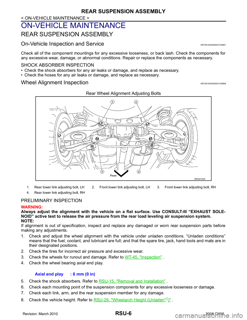
Rear Wheel Alignment Adjusting Bolts
PRELIMINARY INSPECTION
WARNING:
Always adjust the alignment with the vehicle on a flat surface. Use CONSULT-III “EXHAUST SOLE-
NOID” active test to release the air pressure from the rear load leveling air suspension system.
NOTE:
If alignment is out of specificat ion, inspect and replace any damaged or worn rear suspension parts before
making any adjustments.
1. Check and adjust the wheel alignment with the vehicle under unladen conditions. “Unladen conditions”
means that the fuel, coolant, and lubricant are full; and that the spare tire, jack, hand tools and mats are in
their designated positions.
2. Check the tires for incorrect air pressure and excessive wear.
3. Check the wheels for runout and damage. Refer to WT-45, "
Inspection" .
4. Check the wheel bearing axial end play.
5. Check the shock absorbers. Refer to RSU-15, "
Removal and Installation" .
6. Check each mounting point of the suspension components for any excessive looseness or damage.
7. Check each link, arm, and the rear suspension member for any damage.
8. Check the vehicle height. Refer to RSU-29, "
Wheelarch Height (Unladen*1)" .
WEIA0102E
1. Rear lower link adjusting bolt, LH 2. Front lower link adjusting bolt, LH 3. Front lower link adjusting bolt, RH
4. Rear lower link adjusting bolt, RH
Axial end play : 0 mm (0 in)
Revision: March 2010 2008 QX56
Page 3053 of 4083
RSU-14
< REMOVAL AND INSTALLATION >
REAR SUSPENSION MEMBER
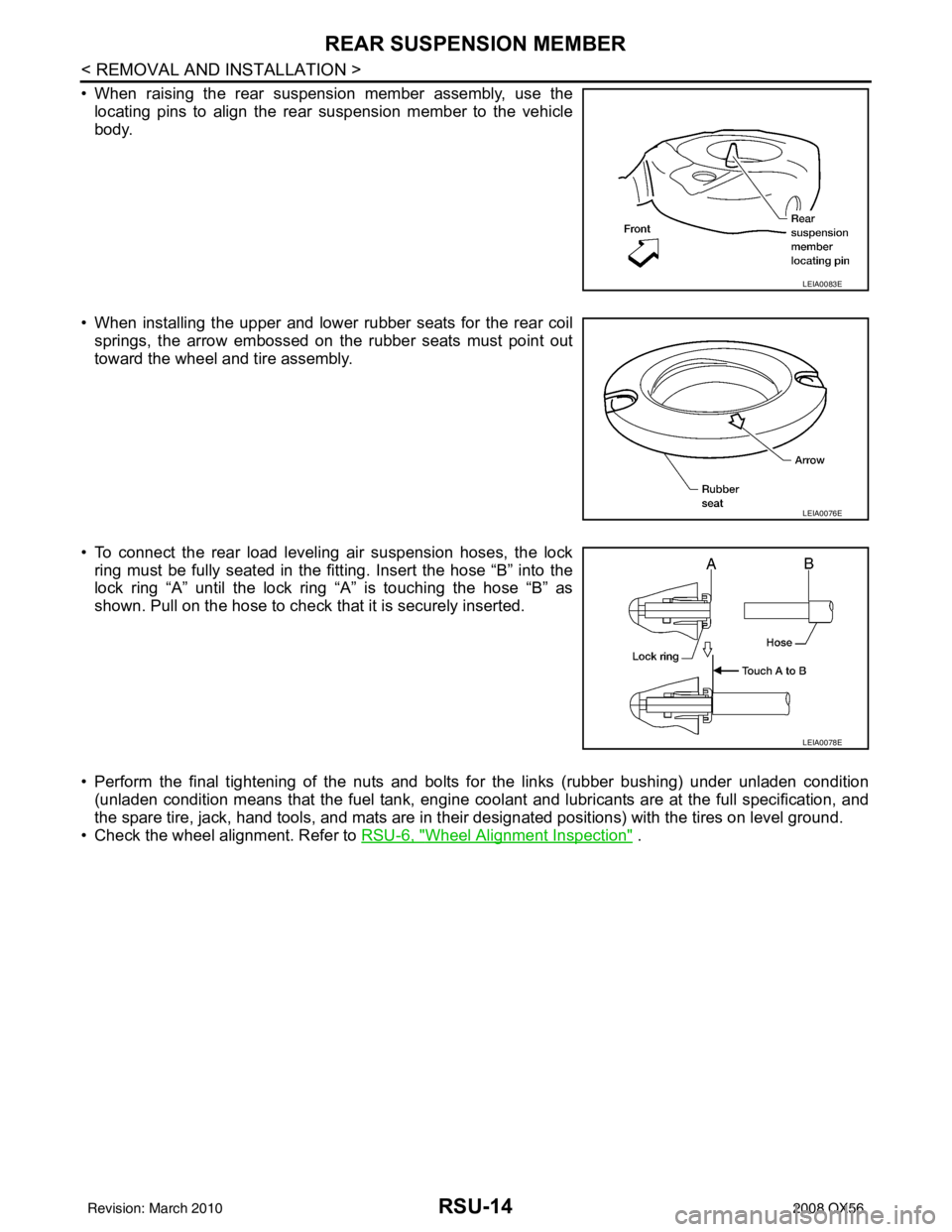
• When raising the rear suspension member assembly, use thelocating pins to align the rear suspension member to the vehicle
body.
• When installing the upper and lower rubber seats for the rear coil springs, the arrow embossed on the rubber seats must point out
toward the wheel and tire assembly.
• To connect the rear load leveling air suspension hoses, the lock ring must be fully seated in the fitt ing. Insert the hose “B” into the
lock ring “A” until the lock ring “A” is touching the hose “B” as
shown. Pull on the hose to check that it is securely inserted.
• Perform the final tightening of the nuts and bolts for the links (rubber bushing) under unladen condition (unladen condition means that the fuel tank, engine cool ant and lubricants are at the full specification, and
the spare tire, jack, hand tools, and mats are in t heir designated positions) with the tires on level ground.
• Check the wheel alignment. Refer to RSU-6, "
Wheel Alignment Inspection" .
LEIA0083E
LEIA0076E
LEIA0078E
Revision: March 2010 2008 QX56
Page 3064 of 4083
CONTROL UNITRSU-25
< REMOVAL AND INSTALLATION >
C
DF
G H
I
J
K L
M A
B
RSU
N
O P
CONTROL UNIT
Removal and InstallationINFOID:0000000004900764
REMOVAL
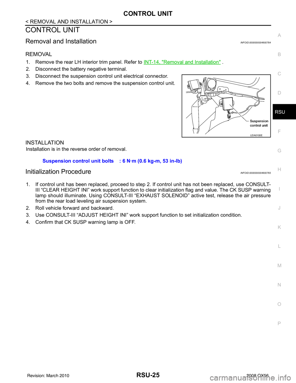
1. Remove the rear LH interior trim panel. Refer to INT-14, "Removal and Installation" .
2. Disconnect the battery negative terminal.
3. Disconnect the suspension control unit electrical connector.
4. Remove the two bolts and remove the suspension control unit.
INSTALLATION
Installation is in the reverse order of removal.
Initialization ProcedureINFOID:0000000004900765
1. If control unit has been replaced, proceed to step 2. If control unit has not been replaced, use CONSULT-
III “CLEAR HEIGHT INI” work support function to cl ear initialization flag and value. The CK SUSP warning
lamp should illuminate. Using CONSULT-III “EXHAUST SOLENOID” active test, release the air pressure
from the rear load leveling air suspension system.
2. Roll vehicle forward and backward.
3. Use CONSULT-III “ADJUST HEIGHT INI” work support function to set initialization condition.
4. Confirm that CK SUSP warning lamp is OFF.
LEIA0100E
Suspension control unit bolt s : 6 N·m (0.6 kg-m, 53 in-lb)
Revision: March 2010 2008 QX56
Page 3090 of 4083
DIAGNOSIS SYSTEM (SUSPENSION CONTROL UNIT)
SCS-7
< FUNCTION DIAGNOSIS >
C
D F
G H
I
J
K L
M A
B
SCS
N
O P
DIAGNOSIS SYSTEM (SUS PENSION CONTROL UNIT)
CONSULT-III FunctionINFOID:0000000001731959
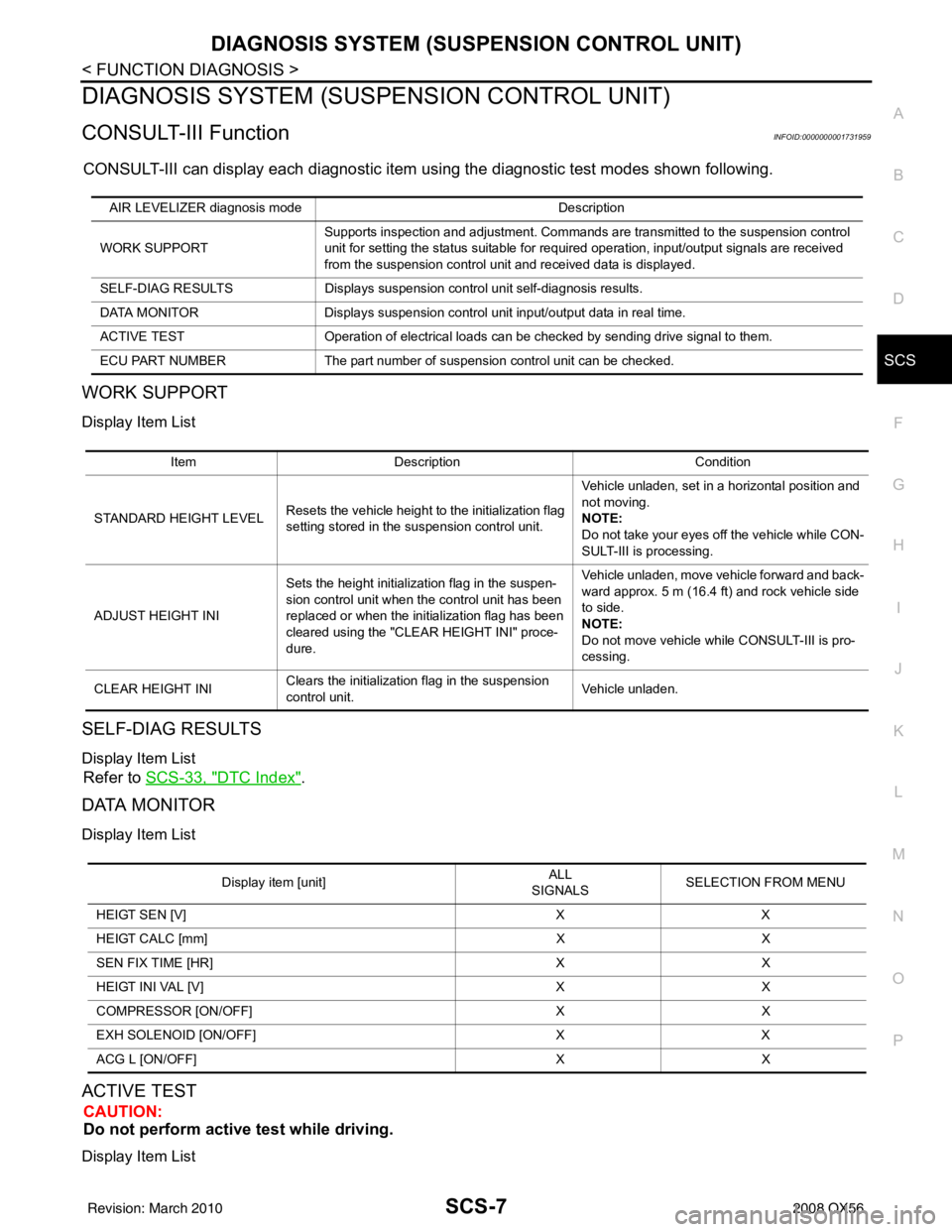
CONSULT-III can display each diagnostic item using the diagnostic test modes shown following.
WORK SUPPORT
Display Item List
SELF-DIAG RESULTS
Display Item List
Refer to SCS-33, "DTC Index".
DATA MONITOR
Display Item List
ACTIVE TEST
CAUTION:
Do not perform active test while driving.
Display Item List
AIR LEVELIZER diagno sis mode Description
WORK SUPPORT Supports inspection and adjustment. Commands are transmitted to the suspension control
unit for setting the status suitable for required operation, input/output signals are received
from the suspension control unit and received data is displayed.
SELF-DIAG RESULTS Displays suspension control unit self-diagnosis results.
DATA MONITOR Displays suspension control unit input/output data in real time.
ACTIVE TEST Operation of electrical loads can be checked by sending drive signal to them.
ECU PART NUMBER The part number of suspension control unit can be checked.
ItemDescription Condition
STANDARD HEIGHT LEVEL Resets the vehicle height to the initialization flag
setting stored in the suspension control unit. Vehicle unladen, set in a horizontal position and
not moving.
NOTE:
Do not take your eyes off the vehicle while CON-
SULT-III is processing.
ADJUST HEIGHT INI Sets the height initialization flag in the suspen-
sion control unit when the control unit has been
replaced or when the initialization flag has been
cleared using the "CLEAR HEIGHT INI" proce-
dure. Vehicle unladen, move vehicle forward and back-
ward approx. 5 m (16.4 ft) and rock vehicle side
to side.
NOTE:
Do not move vehicle wh
ile CONSULT-III is pro-
cessing.
CLEAR HEIGHT INI Clears the initialization flag in the suspension
control unit. Vehicle unladen.
Display item [unit]
ALL
SIGNALS SELECTION FROM MENU
HEIGT SEN [V] XX
HEIGT CALC [mm] XX
SEN FIX TIME [HR] XX
HEIGT INI VAL [V] XX
COMPRESSOR [ON/OFF] XX
EXH SOLENOID [ON/OFF] XX
ACG L [ON/OFF] XX
Revision: March 2010 2008 QX56
Page 3110 of 4083
SUSPENSION CONTROL UNITSCS-27
< ECU DIAGNOSIS >
C
DF
G H
I
J
K L
M A
B
SCS
N
O P
ECU DIAGNOSIS
SUSPENSION CONTROL UNIT
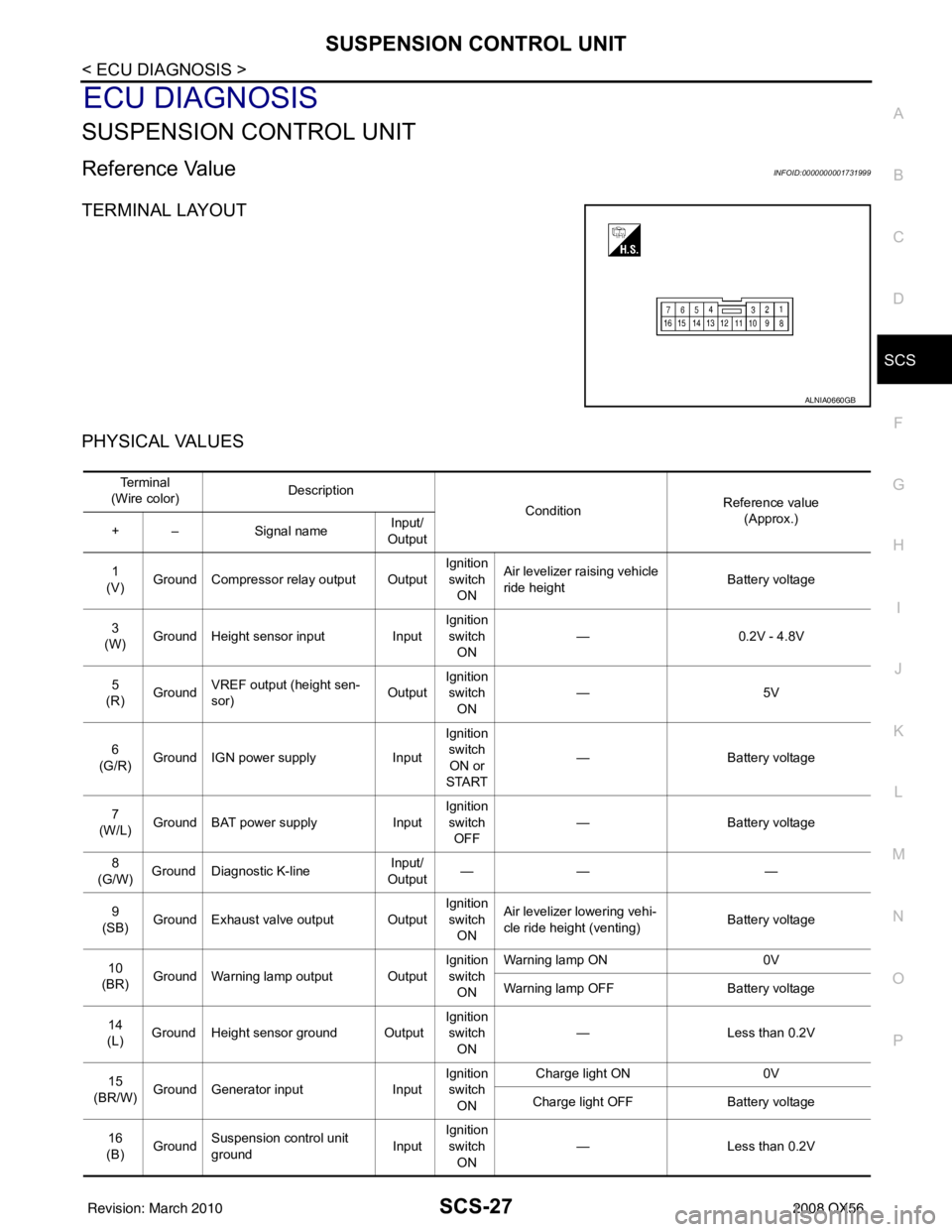
Reference ValueINFOID:0000000001731999
TERMINAL LAYOUT
PHYSICAL VALUES
ALNIA0660GB
Te r m i n a l
(Wire color) Description
ConditionReference value
(Approx.)
+ – Signal nameInput/
Output
1
(V) Ground Compressor relay output Output Ignition
switch
ON Air levelizer ra
ising vehicle
ride height Battery voltage
3
(W) Ground Height sensor input
InputIgnition
switch ON —
0.2V - 4.8V
5
(R) Ground VREF output (height sen-
sor) OutputIgnition
switch ON —5
V
6
(G/R) Ground IGN power supply
InputIgnition
switch
ON or
START —
Battery voltage
7
(W/L) Ground BAT power supply
InputIgnition
switch
OFF —
Battery voltage
8
(G/W) Ground Diagnostic K-line Input/
Output ——
—
9
(SB) Ground Exhaust valve output Output Ignition
switch ON Air levelizer lo
wering vehi-
cle ride height (venting) Battery voltage
10
(BR) Ground Warning lamp output Output Ignition
switch ON Warning lamp ON
0V
Warning lamp OFF Battery voltage
14
(L) Ground Height sensor ground Output Ignition
switch
ON —
Less than 0.2V
15
(BR/W) Ground Generator input
InputIgnition
switch ON Charge light ON
0V
Charge light OFF Battery voltage
16
(B) Ground Suspension control unit
ground InputIgnition
switch ON —
Less than 0.2V
Revision: March 2010 2008 QX56