2008 INFINITI QX56 fuel pump
[x] Cancel search: fuel pumpPage 1793 of 4083
![INFINITI QX56 2008 Factory Service Manual EC-494
< ON-VEHICLE MAINTENANCE >[VK56DE]
FUEL PRESSURE
ON-VEHICLE MAINTENANCE
FUEL PRESSURE
Fuel Pressure CheckINFOID:0000000001351336
FUEL PRESSURE RELEASE
With CONSULT-IIl
1. Turn ignition switch INFINITI QX56 2008 Factory Service Manual EC-494
< ON-VEHICLE MAINTENANCE >[VK56DE]
FUEL PRESSURE
ON-VEHICLE MAINTENANCE
FUEL PRESSURE
Fuel Pressure CheckINFOID:0000000001351336
FUEL PRESSURE RELEASE
With CONSULT-IIl
1. Turn ignition switch](/manual-img/42/57030/w960_57030-1792.png)
EC-494
< ON-VEHICLE MAINTENANCE >[VK56DE]
FUEL PRESSURE
ON-VEHICLE MAINTENANCE
FUEL PRESSURE
Fuel Pressure CheckINFOID:0000000001351336
FUEL PRESSURE RELEASE
With CONSULT-IIl
1. Turn ignition switch ON.
2. Perform “FUEL PRESSURE RELEASE” in
“WORK SUPPORT” mode with CONSULT-IIl.
3. Start engine.
4. After engine stalls, crank it two or three times to release all fuel pressure.
5. Turn ignition switch OFF.
Without CONSULT-IIl
1. Remove fuel pump fuse located in IPDM E/R.
2. Start engine.
3. After engine stalls, crank it two or three times to release all fuel pressure.
4. Turn ignition switch OFF.
5. Reinstall fuel pump fuse after servicing fuel system.
FUEL PRESSURE CHECK
CAUTION:
• Before disconnecting fuel line, release fuel pr essure from fuel line to eliminate danger.
• Be careful not to scratch or get the fuel hose connection area dirty wh en servicing, so that the quick
connector o-ring ma intains sealability.
• Use Fuel Pressure Gauge Kit J-44321 and Fuel Pr essure Adapter J-44321-6 to check fuel pressure.
• Do not perform fuel pressure check with electrical system operating (i.e. lights, rear defog, A/C, etc.).
Fuel pressure gauge may indicate false readings du e to varying engine loads and changes in mani-
fold vacuum.
NOTE:
Prepare pans or saucers under the disconnected fuel line because the fuel may spill out. The fuel pres-
sure cannot be completely released because JA60 models do not have fuel return system.
1. Release fuel pressure to zero. Refer to "FUEL PRESSURE RELEASE".
2. Remove engine cover.
3. Remove fuel hose using Quick Connector Release J-45488. Refer to EM-26
.
• Do not twist or kink fuel hose because it is plastic hose.
• Do not remove fuel hose from quick connector.
• Keep fuel hose connections clean.
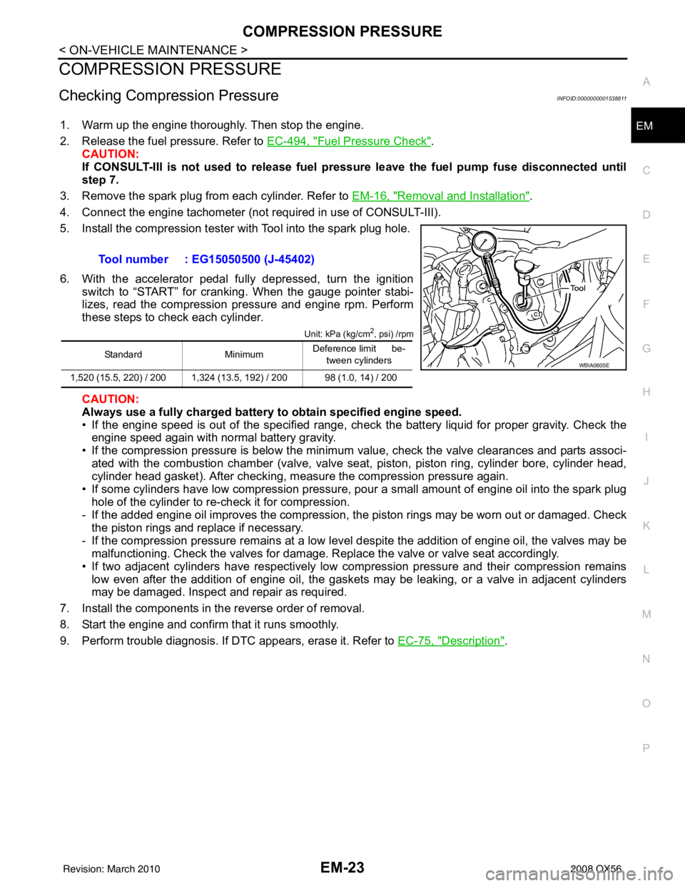
4. Install Fuel Pressure Adapter J-44321-6 and Fuel Pressure Gauge (from kit J-44321) as shown in figure.
• Do not distort or bend fuel rail tube when installing fuel pres-sure gauge adapter.
• When reconnecting fuel hose, check the original fuel hose for damage and abnormality.
5. Turn ignition switch ON (reactivate fuel pump), and check for fuel leakage.
6. Start engine and check for fuel leakage.
7. Read the indication of fuel pressure gauge. • During fuel pressure check, check for fuel leakage from fuelconnection every 3 minutes.
BBIA0380E
BBIA0390E
Revision: March 2010 2008 QX56
Page 1794 of 4083
![INFINITI QX56 2008 Factory Service Manual FUEL PRESSUREEC-495
< ON-VEHICLE MAINTENANCE > [VK56DE]
C
D
E
F
G H
I
J
K L
M A
EC
NP
O
8. If result is unsatisfactory, go to next step.
9. Check the following.
• Fuel hoses and fuel tubes for clogg INFINITI QX56 2008 Factory Service Manual FUEL PRESSUREEC-495
< ON-VEHICLE MAINTENANCE > [VK56DE]
C
D
E
F
G H
I
J
K L
M A
EC
NP
O
8. If result is unsatisfactory, go to next step.
9. Check the following.
• Fuel hoses and fuel tubes for clogg](/manual-img/42/57030/w960_57030-1793.png)
FUEL PRESSUREEC-495
< ON-VEHICLE MAINTENANCE > [VK56DE]
C
D
E
F
G H
I
J
K L
M A
EC
NP
O
8. If result is unsatisfactory, go to next step.
9. Check the following.
• Fuel hoses and fuel tubes for clogging
• Fuel filter for clogging
• Fuel pump
• Fuel pressure regulator for clogging
If OK, replace fuel pressure regulator.
If NG, repair or replace.
10. Before disconnecting Fuel Pressure Gauge and Fuel Pressure Adapter J-44321-6, release fuel pressure
to zero. Refer to "FUEL PRESSURE RELEASE". At idling:
Approximately 350 kPa (3.57 kg/cm
2, 51 psi)
Revision: March 2010 2008 QX56
Page 1795 of 4083
![INFINITI QX56 2008 Factory Service Manual EC-496
< ON-VEHICLE MAINTENANCE >[VK56DE]
EVAP LEAK CHECK
EVAP LEAK CHECK
How to Detect Fuel Vapor LeakageINFOID:0000000001351309
CAUTION:
• Never use compressed air or a high pressure pump.
• Do INFINITI QX56 2008 Factory Service Manual EC-496
< ON-VEHICLE MAINTENANCE >[VK56DE]
EVAP LEAK CHECK
EVAP LEAK CHECK
How to Detect Fuel Vapor LeakageINFOID:0000000001351309
CAUTION:
• Never use compressed air or a high pressure pump.
• Do](/manual-img/42/57030/w960_57030-1794.png)
EC-496
< ON-VEHICLE MAINTENANCE >[VK56DE]
EVAP LEAK CHECK
EVAP LEAK CHECK
How to Detect Fuel Vapor LeakageINFOID:0000000001351309
CAUTION:
• Never use compressed air or a high pressure pump.
• Do not exceed 4.12 kPa (0.042 kg/cm
2, 0.6 psi) of pressure in EVAP system.
NOTE:
• Do not start engine.
• Improper installation of EVAP service port adapter to the EVAP service port may cause a leak.
WITH CONSULT-IIl
1. Attach the EVAP service port adapter securely to the EVAP service port.
2. Also attach the pressure pump and hose to the EVAP service port adapter.
3. Turn ignition switch ON.
4. Select the “EVAP SYSTEM CLOSE” of “WORK SUPPORT MODE” with CONSULT-IIl.
5. Touch “START”. A bar graph (Pressure indicating display) will appear on the screen.
6. Apply positive pressure to the EVAP system until t he pressure indicator reaches the middle of the bar
graph.
7. Remove EVAP service port adapter and hose with pressure pump.
8. Locate the leak using a leak detector. Refer to EC-37, "
Descrip-
tion".
WITHOUT CONSULT-IIl
1. Attach the EVAP service port adapter securely to the EVAP ser- vice port.
2. Also attach the pressure pump with pressure gauge to the EVAP service port adapter.
SEF200U
BBIA0366E
SEF462UA
Revision: March 2010 2008 QX56
Page 1803 of 4083
![INFINITI QX56 2008 Factory Service Manual EC-504
< SERVICE DATA AND SPECIFICATIONS (SDS) [VK56DE]
SERVICE DATA AND SPECIFICATIONS (SDS)
Heated Oxygen sensor 2 Heater
INFOID:0000000001366039
Crankshaft Position Sensor (POS)INFOID:0000000001366 INFINITI QX56 2008 Factory Service Manual EC-504
< SERVICE DATA AND SPECIFICATIONS (SDS) [VK56DE]
SERVICE DATA AND SPECIFICATIONS (SDS)
Heated Oxygen sensor 2 Heater
INFOID:0000000001366039
Crankshaft Position Sensor (POS)INFOID:0000000001366](/manual-img/42/57030/w960_57030-1802.png)
EC-504
< SERVICE DATA AND SPECIFICATIONS (SDS) [VK56DE]
SERVICE DATA AND SPECIFICATIONS (SDS)
Heated Oxygen sensor 2 Heater
INFOID:0000000001366039
Crankshaft Position Sensor (POS)INFOID:0000000001366040
Refer to EC-209, "Component Inspection".
Camshaft Position Sensor (PHASE)INFOID:0000000001366041
Refer to EC-213, "Component Inspection".
Throttle Control MotorINFOID:0000000001366042
Fuel InjectorINFOID:0000000001366043
Fuel PumpINFOID:0000000001366044
Resistance [at 25 °C (77 °F)] 8 - 10 Ω
Resistance [at 25°C (77 °F)] Approximately 1 - 15 Ω
Resistance [at 10 - 60°C (50 - 140 °F)] 11.1 - 14.5Ω
Resistance [at 25 °C (77 °F)] 0.2 - 5.0 Ω
Revision: March 2010 2008 QX56
Page 1826 of 4083

COMPRESSION PRESSUREEM-23
< ON-VEHICLE MAINTENANCE >
C
DE
F
G H
I
J
K L
M A
EM
NP
O
COMPRESSION PRESSURE
Checking Compression PressureINFOID:0000000001538811
1. Warm up the engine thoroughly. Then stop the engine.
2. Release the fuel pressure. Refer to EC-494, "
Fuel Pressure Check".
CAUTION:
If CONSULT-III is not used to release fuel pressure leave the fuel pump fuse disconnected until
step 7.
3. Remove the spark plug from each cylinder. Refer to EM-16, "
Removal and Installation".
4. Connect the engine tachometer (not required in use of CONSULT-III).
5. Install the compression tester with Tool into the spark plug hole.
6. With the accelerator pedal fully depressed, turn the ignition switch to “START” for cranking. When the gauge pointer stabi-
lizes, read the compression pressure and engine rpm. Perform
these steps to check each cylinder.
Unit: kPa (kg/cm2, psi) /rpm
CAUTION:
Always use a fully charged battery to obtain specified engine speed.
• If the engine speed is out of the specified range, check the battery liquid for proper gravity. Check the engine speed again with normal battery gravity.
• If the compression pressure is below the minimum value, check the valve clearances and parts associ-
ated with the combustion chamber (valve, valve seat , piston, piston ring, cylinder bore, cylinder head,
cylinder head gasket). After checking, measure the compression pressure again.
• If some cylinders have low compression pressure, pour a small amount of engine oil into the spark plug hole of the cylinder to re-check it for compression.
- If the added engine oil improves the compression, t he piston rings may be worn out or damaged. Check
the piston rings and replace if necessary.
- If the compression pressure remains at a low level despite the addition of engine oil, the valves may be malfunctioning. Check the valves for damage. Replace the valve or valve seat accordingly.
• If two adjacent cylinders have respectively low compression pressure and their compression remains low even after the addition of engine oil, the gaskets may be leaking, or a valve in adjacent cylinders
may be damaged. Inspect and repair as required.
7. Install the components in the reverse order of removal.
8. Start the engine and confirm that it runs smoothly.
9. Perform trouble diagnosis. If DTC appears, erase it. Refer to EC-75, "
Description".
Tool number : EG15050500 (J-45402)
Standard
MinimumDeference limit be-
tween cylinders
1,520 (15.5, 220) / 200 1,324 (13.5, 192) / 200 98 (1.0, 14) / 200WBIA0605E
Revision: March 2010 2008 QX56
Page 1871 of 4083

EM-68
< ON-VEHICLE REPAIR >
CYLINDER HEAD
CYLINDER HEAD
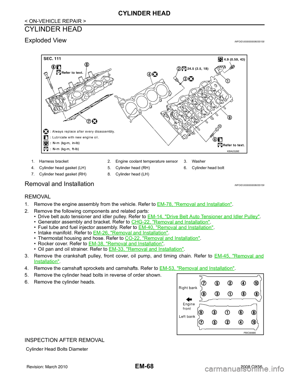
Exploded ViewINFOID:0000000006055158
Removal and InstallationINFOID:0000000006055159
REMOVAL
1. Remove the engine assembly from the vehicle. Refer to EM-78, "Removal and Installation".
2. Remove the following components and related parts: • Drive belt auto tensioner and idler pulley. Refer to EM-14, "
Drive Belt Auto Tensioner and Idler Pulley".
• Generator assembly and bracket. Refer to CHG-22, "
Removal and Installation".
• Fuel tube and fuel injector assembly. Refer to EM-40, "
Removal and Installation".
• Intake manifold. Refer to EM-26, "
Removal and Installation".
• Thermostat housing and hose. Refer to CO-22, "
Removal and Installation".
• Rocker cover. Refer to EM-38, "
Removal and Installation".
• Oil pan and oil strainer. Refer to EM-33, "
Removal and Installation".
3. Remove the crankshaft pulley, front cover, oil pump, and timing chain. Refer to EM-45, "
Removal and
Installation".
4. Remove the camshaft sprockets and camshafts. Refer to EM-53, "
Removal and Installation".
5. Remove the cylinder head bolts in reverse of order shown.
6. Remove the cylinder heads.
INSPECTION AFTER REMOVAL
Cylinder Head Bolts Diameter
1. Harness bracket 2. Engine coolant temperature sensor 3. Washer
4. Cylinder head gasket (LH) 5. Cylinder head (RH) 6. Cylinder head bolt
7. Cylinder head gasket (RH) 8. Cylinder head (LH)
KBIA2528E
PBIC0068E
Revision: March 2010 2008 QX56
Page 1882 of 4083

ENGINE ASSEMBLYEM-79
< REMOVAL AND INSTALLATION >
C
DE
F
G H
I
J
K L
M A
EM
NP
O
4. Remove the engine hood. Refer to
DLK-224, "Removal and Installation of Hood Assembly".
5. Remove the cowl extension. Refer to EXT-18, "
Removal and Installation".
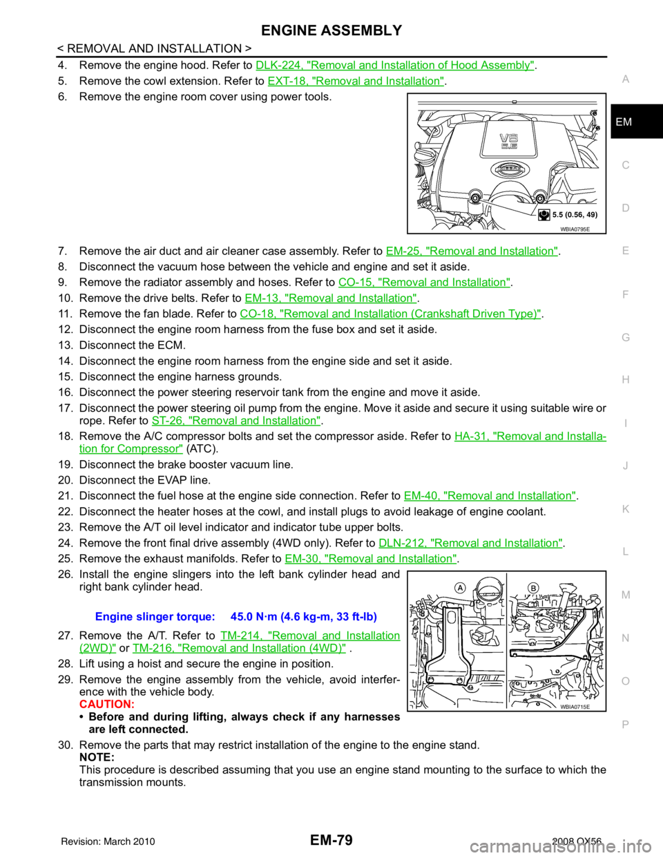
6. Remove the engine room cover using power tools.
7. Remove the air duct and air cleaner case assembly. Refer to EM-25, "
Removal and Installation".
8. Disconnect the vacuum hose between the vehicle and engine and set it aside.
9. Remove the radiator assembly and hoses. Refer to CO-15, "
Removal and Installation".
10. Remove the drive belts. Refer to EM-13, "
Removal and Installation".
11. Remove the fan blade. Refer to CO-18, "
Removal and Installation (Crankshaft Driven Type)".
12. Disconnect the engine room harness from the fuse box and set it aside.
13. Disconnect the ECM.
14. Disconnect the engine room harness from the engine side and set it aside.
15. Disconnect the engine harness grounds.
16. Disconnect the power steering reservoir t ank from the engine and move it aside.
17. Disconnect the power steering oil pump from the engine. Move it aside and secure it using suitable wire or rope. Refer to ST-26, "
Removal and Installation".
18. Remove the A/C compressor bolts and set the compressor aside. Refer to HA-31, "
Removal and Installa-
tion for Compressor" (ATC).
19. Disconnect the brake booster vacuum line.
20. Disconnect the EVAP line.
21. Disconnect the fuel hose at the engine side connection. Refer to EM-40, "
Removal and Installation".
22. Disconnect the heater hoses at the cowl, and in stall plugs to avoid leakage of engine coolant.
23. Remove the A/T oil level indicator and indicator tube upper bolts.
24. Remove the front final drive assembly (4WD only). Refer to DLN-212, "
Removal and Installation".
25. Remove the exhaust manifolds. Refer to EM-30, "
Removal and Installation".
26. Install the engine slingers into the left bank cylinder head and right bank cylinder head.
27. Remove the A/T. Refer to TM-214, "
Removal and Installation
(2WD)" or TM-216, "Removal and Installation (4WD)" .
28. Lift using a hoist and secure the engine in position.
29. Remove the engine assembly from the vehicle, avoid interfer- ence with the vehicle body.
CAUTION:
• Before and during lifting, always check if any harnessesare left connected.
30. Remove the parts that may restrict installation of the engine to the engine stand. NOTE:
This procedure is described assuming that you use an engine stand mounting to the surface to which the
transmission mounts.
WBIA0795E
Engine slinger torque: 45.0 N·m (4.6 kg-m, 33 ft-lb)
WBIA0715E
Revision: March 2010 2008 QX56
Page 2101 of 4083

FL-1
ENGINE
C
DE
F
G H
I
J
K L
M
SECTION FL
A
FL
N
O P
CONTENTS
FUEL SYSTEM
PRECAUTION ....... ........................................2
PRECAUTIONS .............................................. .....2
Precaution for Supplemental Restraint System
(SRS) "AIR BAG" and "SEAT BELT PRE-TEN-
SIONER" ............................................................. ......
2
Precaution Necessary for Steering Wheel Rota-
tion After Battery Disconnect ............................... ......
2
FUEL SYSTEM ....................................................4
General Precaution ............................................. ......4
PREPARATION ............................................5
PREPARATION .............................................. .....5
Special Service Tool ........................................... ......5
Commercial Service Tool ..........................................5
BASIC INSPECTION ....................................6
FUEL SYSTEM ............................................... .....6
Checking Fuel Line ............................................. ......6
REMOVAL AND INSTALLATION ................7
FUEL LEVEL SENSOR UNIT, FUEL FILTER
AND FUEL PUMP ASSEMBLY .........................
7
Removal and Installation ..................................... .....7
FUEL TANK ......................................................11
Removal and Installation ..................................... ....11
DISASSEMBLY AND ASSEMBLY ..............16
FUEL LEVEL SENSOR UNIT, FUEL FILTER
AND FUEL PUMP ASSEMBLY ........................
16
Disassembly and Assembly ................................. ....16
SERVICE DATA AND SPECIFICATIONS
(SDS) ............... .......................................... ...
17
SERVICE DATA AND SPECIFICATIONS
(SDS) .................................................................
17
Standard and Limit .............................................. ....17
Revision: March 2010 2008 QX56