2008 INFINITI QX56 Brake booster
[x] Cancel search: Brake boosterPage 656 of 4083

CCS-16
< FUNCTION DIAGNOSIS >
INTELLIGENT CRUISE CONTROL SYSTEM
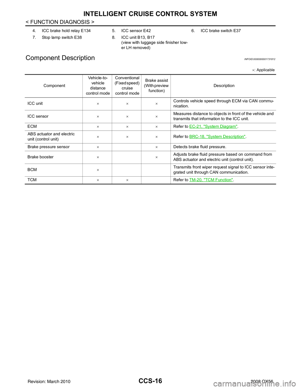
Component Description
INFOID:0000000001731812
× : Applicable
4. ICC brake hold relay E134 5. ICC sensor E426. ICC brake switch E37
7. Stop lamp switch E38 8. ICC unit B13, B17
(view with luggage side finisher low-
er LH removed)
Component Veh ic le-t o-
vehicle
distance
control mode Conventional
(Fixed speed)
cruise
control mode Brake assist
(With preview function) Description
ICC unit ××× Controls vehicle speed through ECM via CAN commu-
nication.
ICC sensor ××× Measures distance to objects in front of the vehicle and
transmits that information to the ICC unit.
ECM ××× Refer to EC-21, "
System Diagram".
ABS actuator and electric
unit (control unit) ×××
Refer to BRC-18, "
System Description".
Brake pressure sensor ×× Detects brake fluid pressure.
Brake booster ×× Adjusts brake fluid pressure based on command from
ABS actuator and electric unit (control unit).
BCM × Transmits front wiper request signal to ICC sensor inte-
grated unit through CAN communication.
TCM ×× Refer to TM-20, "
TCM Function".
Revision: March 2010 2008 QX56
Page 686 of 4083

CCS-46
< ECU DIAGNOSIS >
ICC UNIT
ECU DIAGNOSIS
ICC UNIT
Terminal and Reference Value for ICC UnitINFOID:0000000001756742
Te r m i n a lWire col-
or Item Condition
Voltage (V)
(Approx.)
Ignition
switch Operation
1W/L Battery power supply OFF— Battery voltage
2W/L
5 P CAN-L —— —
7 B/R N-P RANGE ON A/T selector lever in "P" or "N"Battery voltage
10 V/R Brake booster signal ON—
14 L CAN-H —— —
19 B Ground
ON——
20 B
29 BR/W ICC brake switch
(normally closed) Selector le-
ver: Not in “N” or “P” position Depress the brake
pedal
0
Release the brake
pedal Battery voltage
30 L TX —— —
33 R/B Ignition switch power supply ON —
Battery voltage
38 R/G St op la mp sw i tc h
(normally open) OFFDepress the brake pedal
Release the brake pedal
0
39 V/W RX —— —
40 G Parking brake signal
ONParking brake is ON
0
Parking brake is OFF Battery voltage
42 R/B Ignition switch power supply —Battery voltage
46 B Ground ——
47 BR Stop lamp drive output signal Brake operating with ICC system
Battery voltage
Brake not operating with ICC sys-
tem 0
SKIA1243E
Revision: March 2010
2008 QX56
Page 695 of 4083

CCS
ICC UNITCCS-55
< ECU DIAGNOSIS >
C
DE
F
G H
I
J
K L
M B
N P A
Diagnostic Trouble Code (DTC) ChartINFOID:0000000001757410
× :Applicable
DTC
No. CONSULT-III screen terms ICC sys-
tem
warning lamp Fail-safe
Malfunctions detected where... Refer-
ence
page
Veh ic le-
to-vehi-cle dis-
tance
control mode Conven-
tional
(fixed
speed) cruise
control mode Brake as-
sist (with
preview
function)
11 CONTROL UNIT ×××× • ICC unit internal malfunctionCCS-22
12 VDC CONTROL UNIT ×××× • VDC malfunction
• Brake booster signal harness is
open or shorted CCS-23
20 CAN COMM CIRCUIT
×××× • ICC unit detected CAN communi-
cation malfunction CCS-24
31 POWER SUPPLY CIR1
×××× • ICC unit power supply voltage is
excessively low (less than 8V) CCS-25
34 POWER SUPPLY CIR2
×××× • ICC unit power supply voltage is
excessively high. CCS-25
41 VHCL SPEED SE CIRC
×××× • Wheel sensor malfunction
• ABS actuator and electric unit
(control unit) malfunction
• A/T vehicle speed sensor mal-
function
•TCM malfunction CCS-26
43 VDC/TCS/ABS CIRC
×××× • VDC/TCS/ABS system malfunc-
tion CCS-27
45 BRAKE SW/ STOP L SW
×××× • ICC brake switch or stop lamp
switch harness is open or shorted
• ICC brake switch or stop lamp switch is stuck to OFF
• ICC brake switch or stop lamp switch is stuck to ON CCS-28
46 OPERATION SW CIRC
××× • ICC steering switch harness or
spiral cable is open or shorted
• ICC steering switch malfunction CCS-30
74 LASER BEAM OFF CNTR
××ו Laser beam of ICC sensor is off
the aiming point CCS-31
90 STOP LAMP RLY FIX
××ו Normally open terminal of stop
lamp relay is stuck CCS-32
92 ECM CIRCUIT
×××× •ECM malfunction
• Accelerator pedal position sensor
malfunction
• ICC unit malfunction CCS-37
96 NP RANGE
××× • Transmission range switch har-
ness is open or shorted
• Transmission range switch mal- function
•TCM malfunction CCS-38
97 AT CIRCUIT
××× •TCM malfunctionCCS-39
98 GEAR POSITION ××× •TCM malfunction
• A/T input speed sensor malfunc-
tion
• A/T vehicle speed sensor mal- function CCS-40
Revision: March 2010
2008 QX56
Page 1882 of 4083

ENGINE ASSEMBLYEM-79
< REMOVAL AND INSTALLATION >
C
DE
F
G H
I
J
K L
M A
EM
NP
O
4. Remove the engine hood. Refer to
DLK-224, "Removal and Installation of Hood Assembly".
5. Remove the cowl extension. Refer to EXT-18, "
Removal and Installation".
6. Remove the engine room cover using power tools.
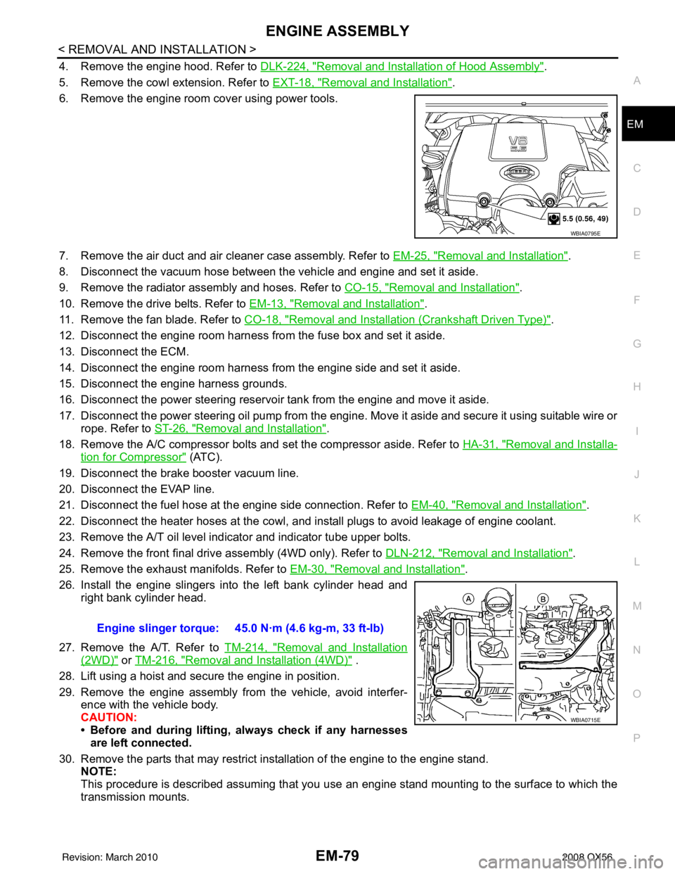
7. Remove the air duct and air cleaner case assembly. Refer to EM-25, "
Removal and Installation".
8. Disconnect the vacuum hose between the vehicle and engine and set it aside.
9. Remove the radiator assembly and hoses. Refer to CO-15, "
Removal and Installation".
10. Remove the drive belts. Refer to EM-13, "
Removal and Installation".
11. Remove the fan blade. Refer to CO-18, "
Removal and Installation (Crankshaft Driven Type)".
12. Disconnect the engine room harness from the fuse box and set it aside.
13. Disconnect the ECM.
14. Disconnect the engine room harness from the engine side and set it aside.
15. Disconnect the engine harness grounds.
16. Disconnect the power steering reservoir t ank from the engine and move it aside.
17. Disconnect the power steering oil pump from the engine. Move it aside and secure it using suitable wire or rope. Refer to ST-26, "
Removal and Installation".
18. Remove the A/C compressor bolts and set the compressor aside. Refer to HA-31, "
Removal and Installa-
tion for Compressor" (ATC).
19. Disconnect the brake booster vacuum line.
20. Disconnect the EVAP line.
21. Disconnect the fuel hose at the engine side connection. Refer to EM-40, "
Removal and Installation".
22. Disconnect the heater hoses at the cowl, and in stall plugs to avoid leakage of engine coolant.
23. Remove the A/T oil level indicator and indicator tube upper bolts.
24. Remove the front final drive assembly (4WD only). Refer to DLN-212, "
Removal and Installation".
25. Remove the exhaust manifolds. Refer to EM-30, "
Removal and Installation".
26. Install the engine slingers into the left bank cylinder head and right bank cylinder head.
27. Remove the A/T. Refer to TM-214, "
Removal and Installation
(2WD)" or TM-216, "Removal and Installation (4WD)" .
28. Lift using a hoist and secure the engine in position.
29. Remove the engine assembly from the vehicle, avoid interfer- ence with the vehicle body.
CAUTION:
• Before and during lifting, always check if any harnessesare left connected.
30. Remove the parts that may restrict installation of the engine to the engine stand. NOTE:
This procedure is described assuming that you use an engine stand mounting to the surface to which the
transmission mounts.
WBIA0795E
Engine slinger torque: 45.0 N·m (4.6 kg-m, 33 ft-lb)
WBIA0715E
Revision: March 2010 2008 QX56
Page 2605 of 4083

GENERAL MAINTENANCEMA-7
< ON-VEHICLE MAINTENANCE >
C
DE
F
G H
I
J
K L
M B
MA
N
O A
UNDER THE HOOD AND VEHICLE
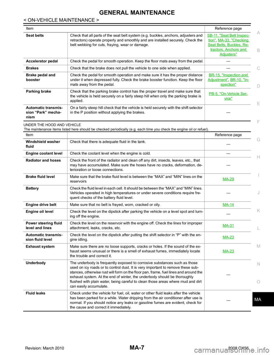
The maintenance items listed here should be checked periodically (e.g. each time you check the engine oil or refuel).
Seat beltsCheck that all parts of the seat belt system (e.g. buckles, anchors, adjusters and
retractors) operate properly and smoothly and are installed securely. Check the
belt webbing for cuts, fraying, wear or damage. SB-11, "Seat Belt Inspec-
tion", MA-33, "Checking
Seat Belts, Buckles, Re-
tractors, Anchors and
Adjusters"
Accelerator pedal
Check the pedal for smooth operation. Keep the floor mats away from the pedal. —
Brakes Check that the brake does not pull the vehicle to one side when applied. —
Brake pedal and
booster Check the pedal for smooth operation and make sure it has the proper distance
under it when depressed fully. Check the brake booster function. Keep the floor
mats away from the pedal. BR-15, "
Inspection and
Adjustment", BR-10, "In-
spection"
Parking brake
Check that the parking brake control has the proper travel and make sure that
the vehicle is held securely on a fairly steep hill when only the parking brake is
applied. PB-5, "On-Vehicle Ser-
vice"
Automatic transmis-
sion “Park” mecha-
nismOn a fairly steep hill check that the vehicle is held securely with the shift selector
in the P position without applying the brakes.
—
Item
Reference page
Item Reference page
Windshield washer
fluid Check that there is adequate fluid in the tank.
—
Engine coolant level Check the coolant level when the engine is cold. —
Radiator and hoses Check the front of the radiator and clean off any dirt, insects, leaves, etc., that
may have accumulated. Make sure the hoses have no cracks, deformation, de-
terioration or loose connections. —
Brake fluid level Make sure that the brake fluid level is between the “MAX” and “MIN” lines on the
reservoirs MA-29
Battery
Check the fluid level in each cell. It should be between the “MAX” and “MIN” lines.
Vehicles operated in high temperatures or under severe conditions require fre-
quent checks of the battery fluid level. —
Engine drive belt Make sure that no belt is frayed, worn, cracked or oily. MA-14
Engine oil levelCheck the level on the dipstick after parking the vehicle on a level spot and turn-
ing off the engine. —
Power steering fluid
level and lines Check the level on the reservoir with the engine off. Check the lines for improper
attachment, leaks, cracks, etc.
MA-31
Automatic transmis-
sion fluid levelCheck the level on the dipstick after putting the shift selector in “P” with the en-
gine idling.
MA-23
Exhaust system
Make sure there are no loose supports, cracks or holes. If the sound of the ex-
haust seems unusual or there is a smell of exhaust fumes, immediately locate
the trouble and correct it. MA-23
Underbody
The underbody is frequently exposed to corrosive substances such as those
used on icy roads or to control dust. It is very important to remove these sub-
stances, otherwise rust will form on the floor pan, frame, fuel lines and around the
exhaust system. At the end of winter, the underbody should be thoroughly
flushed with plain water, being careful to clean those areas where mud and dirt
can easily accumulate. —
Fluid leaks Check under the vehicle for fuel, oil, water or other fluid leaks after the vehicle
has been parked for a while. Water dripping from the air conditioner after use is
normal. If you should notice any leaks or gasoline fumes are evident, check for
the cause and correct it immediately. —
Revision: March 2010
2008 QX56
Page 2812 of 4083

PG
HARNESSPG-45
< COMPONENT DIAGNOSIS >
C
DE
F
G H
I
J
K L
B A
O P
N
C1 E5 W/24 : To F14
C1 E119 W/16: IPDM E/R (intelligent power distri-
bution module engine room)
C2 E7 GR/2 : Fusible link box (battery) D1 E120 W/6: IPDM E/R (intelligent power distri-
bution module engine room)
C2 E9 — : Body ground E1 E121 BR/12: IPDM E/R (intelligent power distri-
bution module engine room)
D4 E11 B/8 : Front combination lamp LH (without
daytime running lights) C1 E122 W/12: IPDM E/R (intelligent power distri-
bution module engine room)
D4 E11 B/8 : Front combination lamp LH (with
daytime running lights)
C1 E123 BR/8: IPDM E/R (intelligent power distri-
bution module engine room)
D3 E12 B/5 : Stop lamp relay D1 E124 W/6: IPDM E/R (intelligent power distri-
bution module engine room)
D4 E14 — : Body ground F3 E125 B/47: ABS actuator and electric unit
(control unit)
C2 E15 — : Body ground D4 E126 — : Body ground
C1 E16 B/40 : ECM C2 E130 W/2 : Compressor motor relay
E4 E18 GR/2 : Front wheel sensor LH C3 E131 W/2 : Compressor motor relay
D1 E19 W/16 : To F33 C3 E134 GR/6 : ICC brake hold relay
E3 E21 GR/2 : Brake fluid level switch C2 E135 GR/2 : Transfer dropping resister
E2 E23 GR/6 : Front wiper motor C1 E140 BR/6 : Trailer tow relay-2
D4 E24 — : Body ground B2 E153 W/2 : Transfer motor relay
F3 E25 BR/3 : Intelligent key warning buzzer B2 E154 W/2 : Transfer motor relay
C3 E27 BR/2 : Fusible link box (battery) D3 E156 L/4 : Trailer turn relay LH
C2 E30 /1 : Fusible link box (battery )D3 E157 L/4 : Trailer turn relay RH
E3 E31 B/3 : Front pressure sensor D5 E158 B/3 : Front sonar sensor LH outer
E3 E32 B/3 : Rear pressure sensor D5 E159 GR/3 : To E164
E1 E39 W/2 : To F34 B4 E160 GR/3 : To E165
D3 E40 B/3 : To E201 C3 E161 B/3 : Battery current sensor
D3 E41 SMJ : To C1 B4 E162 B/3 : Front sonar sensor LH inner
D3 E42 B/6 : ICC sensor C5 E163 B/3 : Front sonar sensor RH inner
E1 E46 B/5 : Transfer shift high relay D5 E164 GR/3 : To E159
D2 E47 B/5 : Transfer shift lo w relayA4 E165 GR/3 : To E160
C4 E48 B/3 : Refrigerant pressure sensor A3 E166 B/3 : Front sonar sensor RH outer
E3 E49 B/6 : Active booster Engine room sub-harness
D1 E69 L/4 : Transfer shut off relay D3 E201 B/3 : To E40
D5 E101 B/3 : Front turn-fog lamp LH C1 E202 /1 : Fusible link box (battery)
A4 E102 B/3 : Front turn-fog lamp RH C2 E203 — : Engine ground
C3 E103 B/5 : Daytime light relay C3 E204 /1 : Generator
D4 E105 BR/2 : Front and rear washer motor C3 E205 B/3 : Generator
E4 E106 BR/2 : Washer fluid level switch C3 E206 /1 : Generator
B3 E107 B/8 : Front combination lamp LH
C5 E113 W/2 : Cooling fan motor
Revision: March 2010 2008 QX56