Page 2899 of 4083
PWC-58
< ECU DIAGNOSIS >
BCM (BODY CONTROL MODULE)
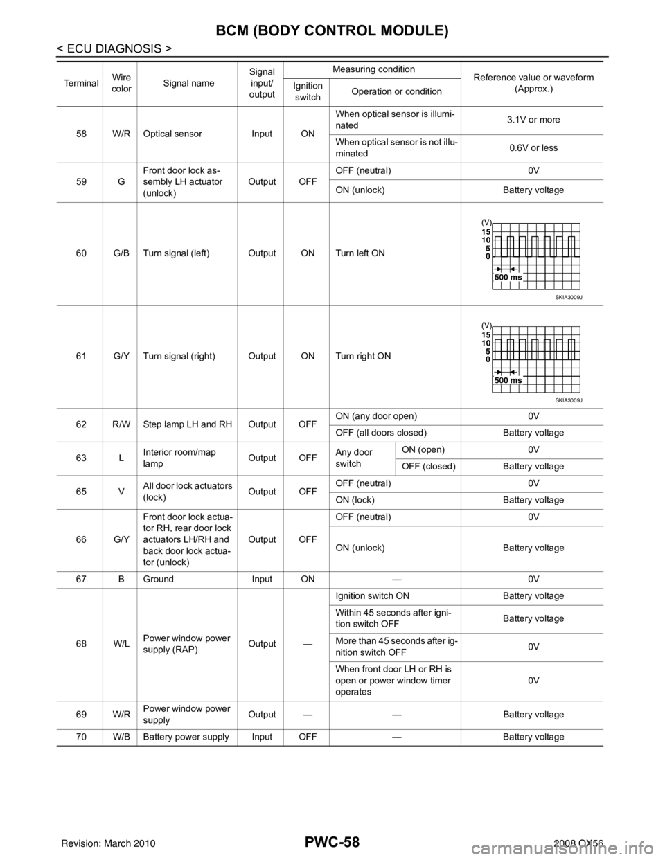
58 W/R Optical sensorInput ONWhen optical sensor is illumi-
nated
3.1V or more
When optical sensor is not illu-
minated 0.6V or less
59 G Front door lock as-
sembly LH actuator
(unlock) Output OFF
OFF (neutral)
0V
ON (unlock) Battery voltage
60 G/B Turn signal (left) Output ON Turn left ON
61 G/Y Turn signal (right) Output ON Turn right ON
62 R/W Step lamp LH and RH Output OFF ON (any door open)
0V
OFF (all doors closed) Battery voltage
63 L Interior room/map
lamp Output OFFAny door
switchON (open)
0V
OFF (closed) Battery voltage
65 V All door lock actuators
(lock) Output OFFOFF (neutral)
0V
ON (lock) Battery voltage
66 G/Y Front door lock actua-
tor RH, rear door lock
actuators LH/RH and
back door lock actua-
tor (unlock) Output OFF
OFF (neutral)
0V
ON (unlock) Battery voltage
67 B Ground Input ON—0V
68 W/L Power window power
supply (RAP) Output —Ignition switch ON
Battery voltage
Within 45 seconds after igni-
tion switch OFF Battery voltage
More than 45 seconds after ig-
nition switch OFF 0V
When front door LH or RH is
open or power window timer
operates 0V
69 W/R Power window power
supply
Output —
—Battery voltage
70 W/B Battery power supply Input OFF —Battery voltage
Te r m i n a l
Wire
color Signal name Signal
input/
output Measuring condition
Reference value or waveform
(Approx.)
Ignition
switch Operation or condition
SKIA3009J
SKIA3009J
Revision: March 2010
2008 QX56
Page 2906 of 4083

POWER WINDOW MAIN SWITCHPWC-65
< ECU DIAGNOSIS >
C
DE
F
G H
I
J
L
M A
B
PWC
N
O P
POWER WINDOW MAIN SWITCH
Reference Value INFOID:0000000001735737
TERMINAL LAYOUT
PHYSICAL VALUES
MAIN POWER WINDOW AND DOOR LOCK/UNLOCK SWITCH
LIIA2455E
Te r m i n a l N o . (Wire color) Description
ConditionVoltage [V]
(Approx.)
+ – Signal name Input/
Output
2
(W/B) Ground Encoder ground
—— 0
4
(L) Ground Door key cylinder switch LH
LOCK signal InputKey position
(Neutral
→ Locked) 5
→ 0
6
(R) Ground Door key cylinder switch LH
UNLOCK signal
InputKey position
(Neutral
→ Unlocked) 5
→ 0
8
(G/R) 11Front door power window mo-
tor LH UP signal
OutputWhen front LH switch in
power window main switch
is operated UP.
Battery voltage
9
(O) 2 Encoder pulse signal 2 Input
When power window mo-
tor operates.
10
(W/L) Ground RAP signal
InputIGN SW ON
Battery voltage
Within 45 second after ig-
nition switch is turned to
OFF. Battery voltage
When front LH or RH door
is opened during retained
power operation. 0
11
(G/W) 8Front door power window mo-
tor LH DOWN signal OutputWhen front LH switch in
power window main switch
is operated DOWN. Battery voltage
JMKIA0070GB
Revision: March 2010
2008 QX56
Page 2907 of 4083
PWC-66
< ECU DIAGNOSIS >
POWER WINDOW MAIN SWITCH
13
(G/Y) 2 Encoder pulse signal 1 Input When power window mo-
tor operates.
14
(LG/W) Ground Power window serial link Input/
Output IGN SW ON or power win-
dow timer operating.
15
(BR) Ground Encoder power supply Output When ignition switch ON or
power window timer oper-
ates.10
17
(B) Ground Ground
—— 0
19
(W/R) Ground Battery power supply
Input— Battery voltage
Te r m i n a l N o .
(Wire color) Description
ConditionVoltage [V]
(Approx.)
+ – Signal name Input/
Output
JMKIA0070GB
JPMIA0013GB
Revision: March 2010 2008 QX56
Page 2921 of 4083
PWC-80
< ECU DIAGNOSIS >
FRONT POWER WINDOW SWITCH
FRONT POWER WINDOW SWITCH
Reference Value INFOID:0000000001735740
TERMINAL LAYOUT
PHYSICAL VALUES
POWER WINDOW AND DOOR LOCK/UNLOCK SWITCH RH
LIIA2454E
Te r m i n a l N o .(Wire color) Description
ConditionVoltage [V]
(Approx.)
+ – Signal nameInput/
Output
3
(W/B) Ground Encoder ground
—— 0
4
(G/R) Ground Encoder power supply Output When ignition switch ON or
power window timer operates
10
8
(L) 9
Power window motor
UP signal Output
When power window motor is
UP at operated. Battery voltage
9
(G) 8Power window motor
DOWN signal OutputWhen power window motor is
DOWN at operated. Battery voltage
10
(W/R) Ground Battery power supply Input
—Battery voltage
11
(B) Ground Ground
—— 0
12
(G/Y) 3 Encoder pulse signal 1 Input When power window motor op-
erates.
JMKIA0070GB
Revision: March 2010
2008 QX56
Page 2989 of 4083
INSPECTION AND ADJUSTMENTRF-5
< BASIC INSPECTION >
C
DE
F
G H
I
J
L
M A
B
RF
N
O P
INSPECTION AND ADJUSTMENT
ADDITIONAL SERVICE WHEN REPLACING CONTROL UNIT
ADDITIONAL SERVICE WHEN REPL ACING CONTROL UNIT : Description
INFOID:0000000001731919
MEMORY RESET PROCEDURE
1. Please observe the following instructi ons at confirming the sunroof operation.
NOTE:
Do not disconnect the electronic power while the sunroof is operating or within 5 seconds after the sunroof
stops. (to wipe-out the memory of lid position and operating friction.)
2. Initialization of system should be conducted after the following conditions.
• When the sunroof motor is changed.
• When the sunroof does not operate normally. (Incomplete initialization conditions)
ADDITIONAL SERVICE WHEN REPLACING CONTROL UNIT : Special Repair Re-
quirement
INFOID:0000000001731920
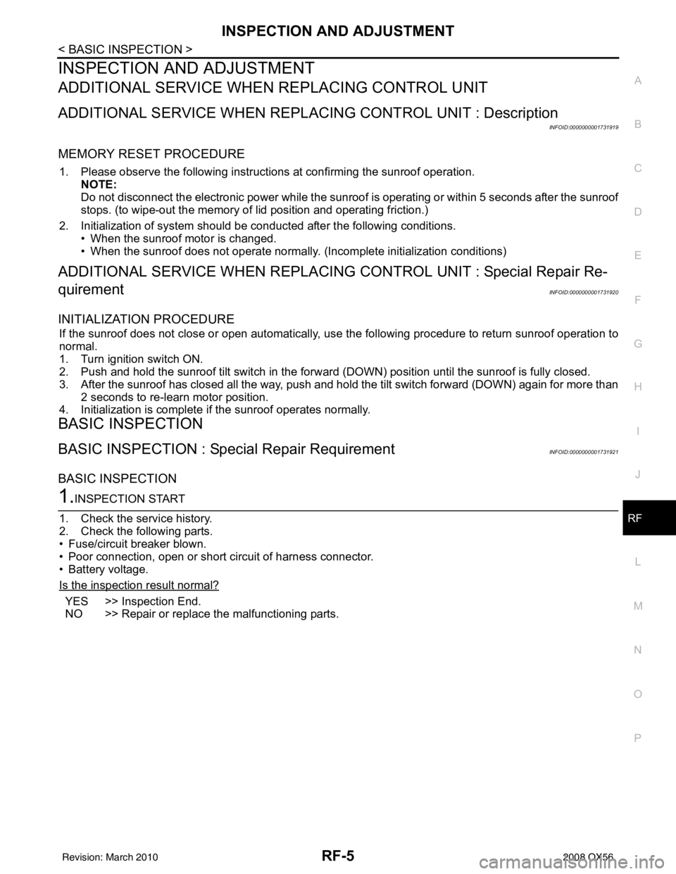
INITIALIZATION PROCEDURE
If the sunroof does not close or open automatically, us e the following procedure to return sunroof operation to
normal.
1. Turn ignition switch ON.
2. Push and hold the sunroof tilt switch in the forw ard (DOWN) position until the sunroof is fully closed.
3. After the sunroof has closed all the way, push and hold the tilt switch forward (DOWN) again for more than 2 seconds to re-learn motor position.
4. Initialization is complete if the sunroof operates normally.
BASIC INSPECTION
BASIC INSPECTION : Special Repair RequirementINFOID:0000000001731921
BASIC INSPECTION
1.INSPECTION START
1. Check the service history.
2. Check the following parts.
• Fuse/circuit breaker blown.
• Poor connection, open or short circuit of harness connector.
• Battery voltage.
Is the inspection result normal?
YES >> Inspection End.
NO >> Repair or replace the malfunctioning parts.
Revision: March 2010 2008 QX56
Page 2994 of 4083
RF-10
< COMPONENT DIAGNOSIS >
POWER SUPPLY AND GROUND CIRCUIT
COMPONENT DIAGNOSIS
POWER SUPPLY AND GROUND CIRCUIT
SUNROOF MOTOR ASSEMBLY
SUNROOF MOTOR ASSEMBLY : Diagnosis ProcedureINFOID:0000000001731928
SUNROOF MOTOR ASSEMBLY
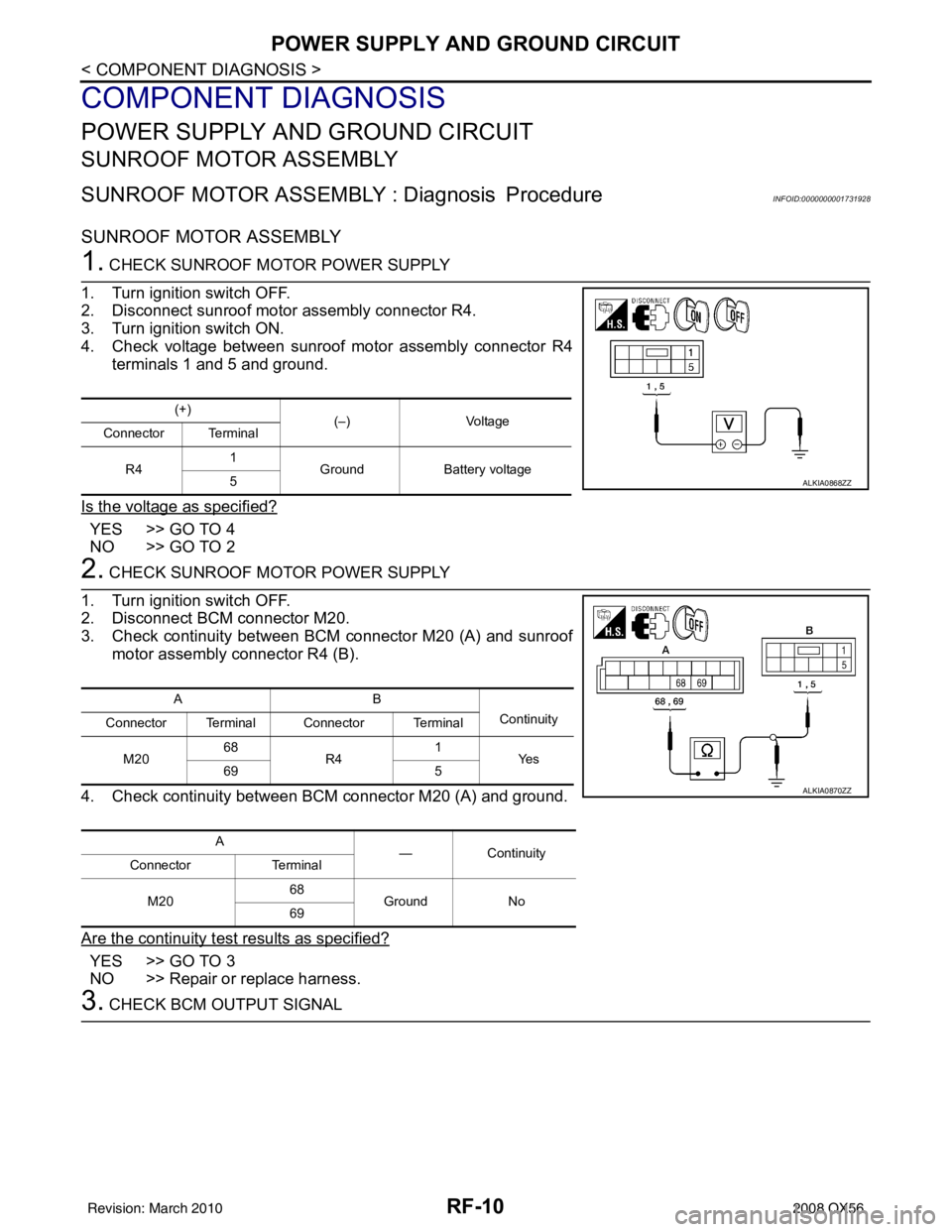
1. CHECK SUNROOF MOTOR POWER SUPPLY
1. Turn ignition switch OFF.
2. Disconnect sunroof motor assembly connector R4.
3. Turn ignition switch ON.
4. Check voltage between sunroof motor assembly connector R4 terminals 1 and 5 and ground.
Is the voltage as specified?
YES >> GO TO 4
NO >> GO TO 2
2. CHECK SUNROOF MOTOR POWER SUPPLY
1. Turn ignition switch OFF.
2. Disconnect BCM connector M20.
3. Check continuity between BCM connector M20 (A) and sunroof motor assembly connector R4 (B).
4. Check continuity between BCM connector M20 (A) and ground.
Are the continuity test results as specified?
YES >> GO TO 3
NO >> Repair or replace harness.
3. CHECK BCM OUTPUT SIGNAL
(+) (–)Voltage
Connector Terminal
R4 1
Ground Battery voltage
5
ALKIA0868ZZ
AB
Continuity
Connector Terminal Connector Terminal
M20 68
R4 1
Ye s
69 5
A —Contin u it y
Connector Terminal
M20 68
Ground No
69
ALKIA0870ZZ
Revision: March 2010 2008 QX56
Page 2995 of 4083
POWER SUPPLY AND GROUND CIRCUITRF-11
< COMPONENT DIAGNOSIS >
C
DE
F
G H
I
J
L
M A
B
RF
N
O P
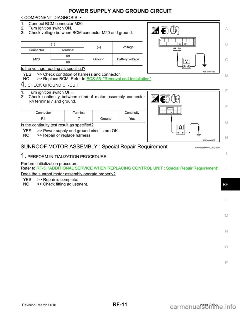
1. Connect BCM connector M20.
2. Turn ignition switch ON.
3. Check voltage between BCM connector M20 and ground.
Is the voltage reading as specified?
YES >> Check condition of harness and connector.
NO >> Replace BCM. Refer to BCS-55, "
Removal and Installation".
4. CHECK GROUND CIRCUIT
1. Turn ignition switch OFF.
2. Check continuity between sunroof motor assembly connector R4 terminal 7 and ground.
Is the continuity test result as specified?
YES >> Power supply and ground circuits are OK.
NO >> Repair or replace harness.
SUNROOF MOTOR ASSEMBLY : Special Repair RequirementINFOID:0000000001731929
1. PERFORM INITIALIZATION PROCEDURE
Perform initialization procedure.
Refer to RF-5, "
ADDITIONAL SERVICE WHEN REPLACING CO NTROL UNIT : Special Repair Requirement".
Does the sunroof motor assembly operate properly?
YES >> Repair is complete.
NO >> Check fitting adjustment.
(+) (–) Voltage
Connector Terminal
M20 68
Ground Battery voltage
69
ALKIA0871ZZ
Connector Terminal—Continuity
R4 7Ground Yes
ALKIA0869ZZ
Revision: March 2010 2008 QX56
Page 2996 of 4083
RF-12
< COMPONENT DIAGNOSIS >
SUNROOF SWITCH CIRCUIT
SUNROOF SWITCH CIRCUIT
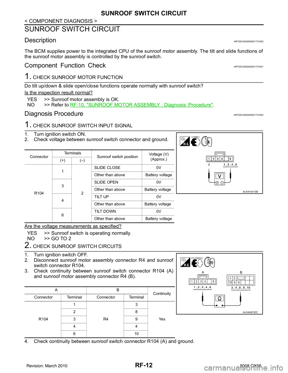
DescriptionINFOID:0000000001731930
The BCM supplies power to the integrated CPU of the sunroof motor assembly. The tilt and slide functions of
the sunroof motor assembly is controlled by the sunroof switch.
Component Function CheckINFOID:0000000001731931
1. CHECK SUNROOF MOTOR FUNCTION
Do tilt up/down & slide open/close functi ons operate normally with sunroof switch?
Is the inspection result normal?
YES >> Sunroof motor assembly is OK.
NO >> Refer to RF-10, "
SUNROOF MOTOR ASSEMBLY : DiagnosisProcedure".
Diagnosis ProcedureINFOID:0000000001731932
1. CHECK SUNROOF SWITCH INPUT SIGNAL
1. Turn ignition switch ON.
2. Check voltage between sunroof switch connector and ground.
Are the voltage measurements as specified?
YES >> Sunroof switch is operating normally.
NO >> GO TO 2
2. CHECK SUNROOF SWITCH CIRCUITS
1. Turn ignition switch OFF.
2. Disconnect sunroof motor assembly connector R4 and sunroof switch connector R104.
3. Check continuity between sunroof switch connector R104 (A) and sunroof motor assembly connector R4 (B).
4. Check continuity between sunroof switch connector R104 (A) and ground.
Connector Te r m i n a l s
Sunroof switch position Voltage (V)
(Approx.)
(+) (–)
R104 1
2SLIDE CLOSE
0V
Other than above Battery voltage
3 SLIDE OPEN
0V
Other than above Battery voltage
4 TILT UP
0V
Other than above Battery voltage
6 TILT DOWN
0V
Other than above Battery voltage
ALKIA1041GB
AB
Continuity
Connector Terminal Connector Terminal
R104 1
R4 3
Ye s
28
39
44
61
0
ALKIA0873ZZ
Revision: March 2010 2008 QX56