2008 INFINITI QX56 key
[x] Cancel search: keyPage 1854 of 4083
TIMING CHAINEM-51
< ON-VEHICLE REPAIR >
C
DE
F
G H
I
J
K L
M A
EM
NP
O
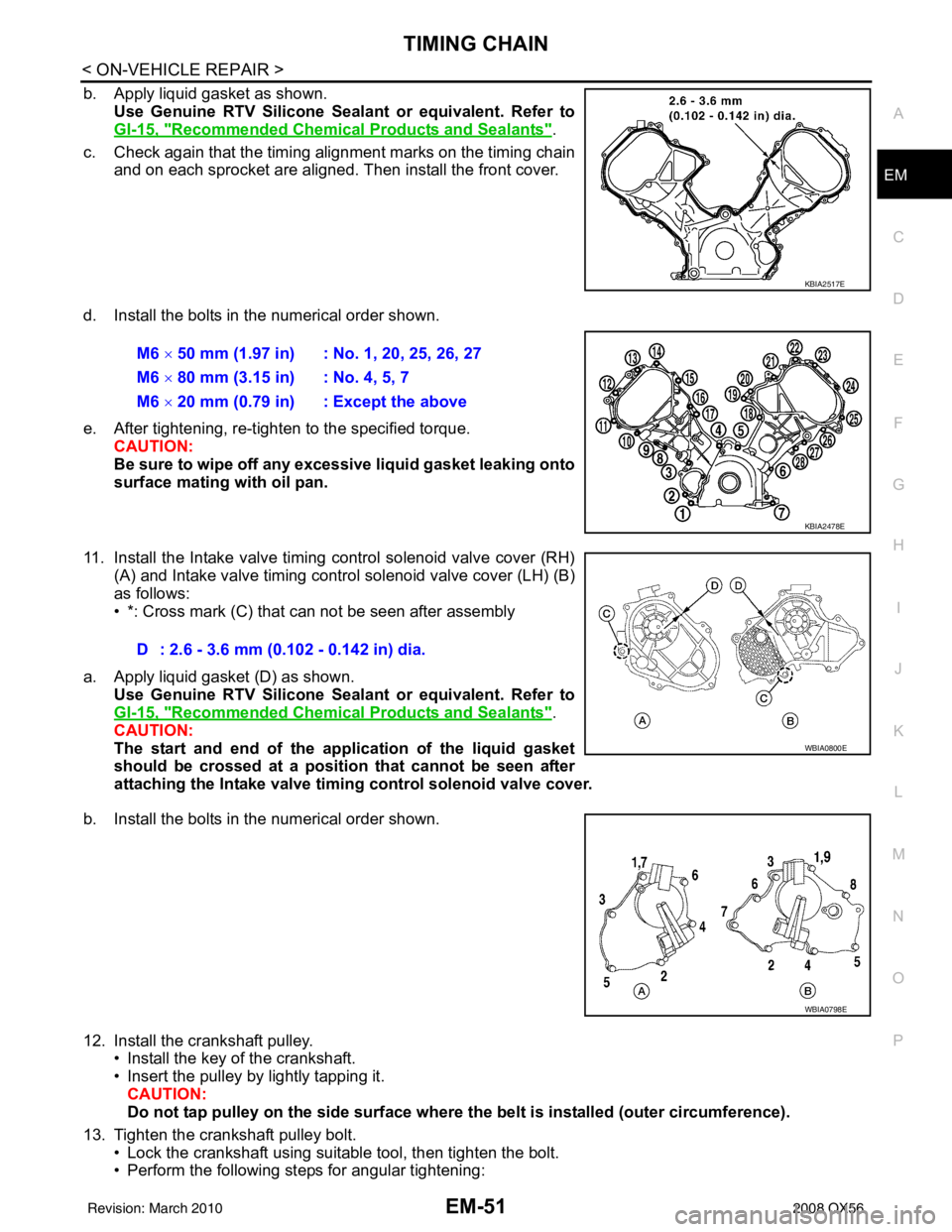
b. Apply liquid gasket as shown.
Use Genuine RTV Silicone Seal ant or equivalent. Refer to
GI-15, "
Recommended Chemical Products and Sealants".
c. Check again that the timing alignment marks on the timing chain and on each sprocket are aligned. Then install the front cover.
d. Install the bolts in the numerical order shown.
e. After tightening, re-tighten to the specified torque. CAUTION:
Be sure to wipe off any excessive liquid gasket leaking onto
surface mating with oil pan.
11. Install the Intake valve timing control solenoid valve cover (RH) (A) and Intake valve timing control solenoid valve cover (LH) (B)
as follows:
• *: Cross mark (C) that can not be seen after assembly
a. Apply liquid gasket (D) as shown. Use Genuine RTV Silicone Seal ant or equivalent. Refer to
GI-15, "
Recommended Chemical Products and Sealants".
CAUTION:
The start and end of the appl ication of the liquid gasket
should be crossed at a positi on that cannot be seen after
attaching the Intake valve timing control solenoid valve cover.
b. Install the bolts in the numerical order shown.
12. Install the crankshaft pulley. • Install the key of the crankshaft.
• Insert the pulley by lightly tapping it.
CAUTION:
Do not tap pulley on the side surface where th e belt is installed (outer circumference).
13. Tighten the crankshaft pulley bolt. • Lock the crankshaft using suitable tool, then tighten the bolt.
• Perform the following steps for angular tightening:
KBIA2517E
M6 × 50 mm (1.97 in) : No. 1, 20, 25, 26, 27
M6 × 80 mm (3.15 in) : No. 4, 5, 7
M6 × 20 mm (0.79 in) : Except the above
KBIA2478E
D : 2.6 - 3.6 mm (0.102 - 0.142 in) dia.
WBIA0800E
WBIA0798E
Revision: March 2010 2008 QX56
Page 1865 of 4083
EM-62
< ON-VEHICLE REPAIR >
CAMSHAFT
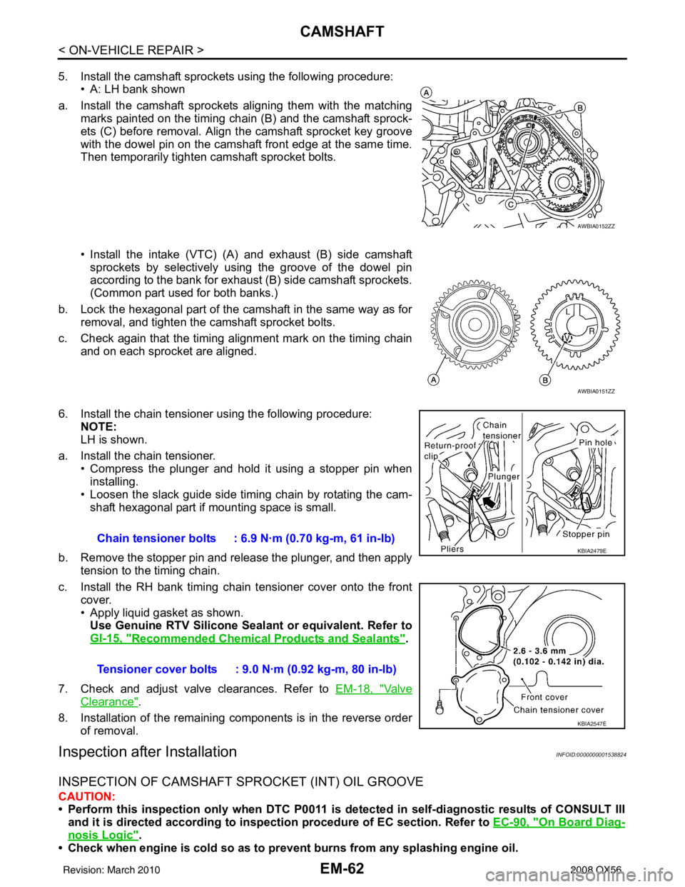
5. Install the camshaft sprockets using the following procedure:• A: LH bank shown
a. Install the camshaft sprockets aligning them with the matching marks painted on the timing chain (B) and the camshaft sprock-
ets (C) before removal. Align the camshaft sprocket key groove
with the dowel pin on the camshaft front edge at the same time.
Then temporarily tighten camshaft sprocket bolts.
• Install the intake (VTC) (A) and exhaust (B) side camshaft
sprockets by selectively using the groove of the dowel pin
according to the bank for exhaust (B) side camshaft sprockets.
(Common part used for both banks.)
b. Lock the hexagonal part of the camshaft in the same way as for removal, and tighten the camshaft sprocket bolts.
c. Check again that the timing alignment mark on the timing chain and on each sprocket are aligned.
6. Install the chain tensioner using the following procedure: NOTE:
LH is shown.
a. Install the chain tensioner. • Compress the plunger and hold it using a stopper pin when
installing.
• Loosen the slack guide side timing chain by rotating the cam- shaft hexagonal part if mounting space is small.
b. Remove the stopper pin and release the plunger, and then apply tension to the timing chain.
c. Install the RH bank timing chain tensioner cover onto the front cover.
• Apply liquid gasket as shown.Use Genuine RTV Silicone Seal ant or equivalent. Refer to
GI-15, "
Recommended Chemical Products and Sealants".
7. Check and adjust valve clearances. Refer to EM-18, "
Va l v e
Clearance".
8. Installation of the remaining components is in the reverse order of removal.
Inspection after InstallationINFOID:0000000001538824
INSPECTION OF CAMSHAFT SPROCKET (INT) OIL GROOVE
CAUTION:
• Perform this inspection only when DTC P0011 is detected in self-diagnostic results of CONSULT III
and it is directed accordi ng to inspection procedure of EC section. Refer to EC-90, "
On Board Diag-
nosis Logic".
• Check when engine is cold so as to pr event burns from any splashing engine oil.
AWBIA0152ZZ
AWBIA0151ZZ
Chain tensioner bolts : 6.9 N·m (0.70 kg-m, 61 in-lb)
Tensioner cover bolts : 9.0 N·m (0.92 kg-m, 80 in-lb)KBIA2479E
KBIA2547E
Revision: March 2010 2008 QX56
Page 1885 of 4083
EM-82
< DISASSEMBLY AND ASSEMBLY >
ENGINE UNIT
DISASSEMBLY AND ASSEMBLY
ENGINE UNIT
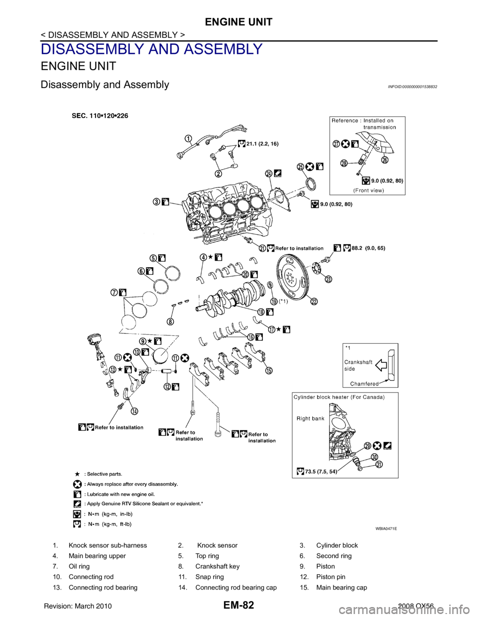
Disassembly and AssemblyINFOID:0000000001538832
1. Knock sensor sub-harness 2. Knock sensor3. Cylinder block
4. Main bearing upper 5. Top ring6. Second ring
7. Oil ring 8. Crankshaft key9. Piston
10. Connecting rod 11. Snap ring12. Piston pin
13. Connecting rod bearing 14. Connecting rod bearing cap 15. Main bearing cap
WBIA0471E
Revision: March 2010 2008 QX56
Page 1923 of 4083
EX-2
< PRECAUTION >
PRECAUTIONS
PRECAUTION
PRECAUTIONS
Precaution for Supplemental Restraint System (SRS) "AIR BAG" and "SEAT BELT
PRE-TENSIONER"
INFOID:0000000004857579
The Supplemental Restraint System such as “A IR BAG” and “SEAT BELT PRE-TENSIONER”, used along
with a front seat belt, helps to reduce the risk or severity of injury to the driver and front passenger for certain
types of collision. This system includes seat belt switch inputs and dual stage front air bag modules. The SRS
system uses the seat belt switches to determine the front air bag deployment, and may only deploy one front
air bag, depending on the severity of a collision and w hether the front occupants are belted or unbelted.
Information necessary to service the system safely is included in the SR and SB section of this Service Man-
ual.
WARNING:
• To avoid rendering the SRS inopera tive, which could increase the risk of personal injury or death in
the event of a collision which would result in air bag inflation, all maintenance must be performed by
an authorized NISSAN/INFINITI dealer.
• Improper maintenance, including in correct removal and installation of the SRS, can lead to personal
injury caused by unintent ional activation of the system. For re moval of Spiral Cable and Air Bag
Module, see the SR section.
• Do not use electrical test equipmen t on any circuit related to the SRS unless instructed to in this
Service Manual. SRS wiring harn esses can be identified by yellow and/or orange harnesses or har-
ness connectors.
PRECAUTIONS WHEN USING POWER TOOLS (AIR OR ELECTRIC) AND HAMMERS
WARNING:
• When working near the Airbag Diagnosis Sensor Unit or other Airbag System sensors with the Igni-
tion ON or engine running, DO NOT use air or electri c power tools or strike near the sensor(s) with a
hammer. Heavy vibration could activate the sensor( s) and deploy the air bag(s), possibly causing
serious injury.
• When using air or electric power tools or hammers , always switch the Ignition OFF, disconnect the
battery, and wait at least 3 minu tes before performing any service.
Precaution Necessary for Steering W heel Rotation After Battery Disconnect
INFOID:0000000004857585
NOTE:
• This Procedure is applied only to models with Intelligent Key system and NATS (NISSAN ANTI-THEFT SYS-
TEM).
• Remove and install all control units after disconnecting both battery cables with the ignition knob in the
″LOCK ″ position.
• Always use CONSULT-III to perform self-diagnosis as a part of each function inspection after finishing work.
If DTC is detected, perform trouble diagnosis according to self-diagnostic results.
For models equipped with the Intelligent Key system and NATS, an electrically controlled steering lock mech-
anism is adopted on the key cylinder.
For this reason, if the battery is disconnected or if the battery is discharged, the steering wheel will lock and
steering wheel rotation will become impossible.
If steering wheel rotation is required when battery pow er is interrupted, follow the procedure below before
starting the repair operation.
OPERATION PROCEDURE
1. Connect both battery cables. NOTE:
Supply power using jumper cables if battery is discharged.
2. Use the Intelligent Key or mechanical key to turn the ignition switch to the ″ACC ″ position. At this time, the
steering lock will be released.
3. Disconnect both battery cables. The steering lock will remain released and the steering wheel can be rotated.
4. Perform the necessary repair operation.
Revision: March 2010 2008 QX56
Page 1944 of 4083
EXL-16
< FUNCTION DIAGNOSIS >
TURN SIGNAL AND HAZARD WARNING LAMPS
TURN SIGNAL AND HAZARD WARNING LAMPS
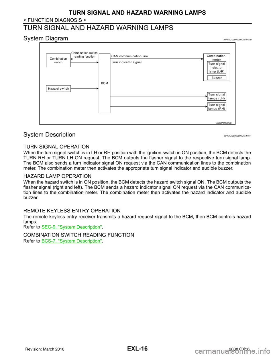
System DiagramINFOID:0000000001547110
System DescriptionINFOID:0000000001547111
TURN SIGNAL OPERATION
When the turn signal switch is in LH or RH position with the ignition switch in ON position, the BCM detects the
TURN RH or TURN LH ON request. The BCM outputs the flasher signal to the respective turn signal lamp.
The BCM also sends a turn indicator signal ON reques t via the CAN communication lines to the combination
meter. The combination meter then activates the appropriate turn signal indicator and audible buzzer.
HAZARD LAMP OPERATION
When the hazard switch is in ON position, the BCM det ects the hazard switch signal ON. The BCM outputs the
flasher signal (right and left). The BCM sends a hazar d indicator signal ON request via the CAN communica-
tion lines to the combination meter. The combination meter then activates the hazard indicator and audible
buzzer.
REMOTE KEYLESS ENTRY OPERATION
The remote keyless entry receiver transmits a hazar d request signal to the BCM, then BCM controls hazard
lamps.
Refer to SEC-9, "
System Description".
COMBINATION SWITCH READING FUNCTION
Refer to BCS-7, "System Description".
AWLIA0006GB
Revision: March 2010 2008 QX56
Page 2036 of 4083
EXL-108
< PRECAUTION >
PRECAUTIONS
PRECAUTION
PRECAUTIONS
Precaution for Supplemental Restraint System (SRS) "AIR BAG" and "SEAT BELT
PRE-TENSIONER"
INFOID:0000000004913877
The Supplemental Restraint System such as “A IR BAG” and “SEAT BELT PRE-TENSIONER”, used along
with a front seat belt, helps to reduce the risk or severity of injury to the driver and front passenger for certain
types of collision. This system includes seat belt switch inputs and dual stage front air bag modules. The SRS
system uses the seat belt switches to determine the front air bag deployment, and may only deploy one front
air bag, depending on the severity of a collision and w hether the front occupants are belted or unbelted.
Information necessary to service the system safely is included in the SR and SB section of this Service Man-
ual.
WARNING:
• To avoid rendering the SRS inopera tive, which could increase the risk of personal injury or death in
the event of a collision which would result in air bag inflation, all maintenance must be performed by
an authorized NISSAN/INFINITI dealer.
• Improper maintenance, including in correct removal and installation of the SRS, can lead to personal
injury caused by unintent ional activation of the system. For re moval of Spiral Cable and Air Bag
Module, see the SR section.
• Do not use electrical test equipmen t on any circuit related to the SRS unless instructed to in this
Service Manual. SRS wiring harn esses can be identified by yellow and/or orange harnesses or har-
ness connectors.
PRECAUTIONS WHEN USING POWER TOOLS (AIR OR ELECTRIC) AND HAMMERS
WARNING:
• When working near the Airbag Diagnosis Sensor Unit or other Airbag System sensors with the Igni-
tion ON or engine running, DO NOT use air or electri c power tools or strike near the sensor(s) with a
hammer. Heavy vibration could activate the sensor( s) and deploy the air bag(s), possibly causing
serious injury.
• When using air or electric power tools or hammers , always switch the Ignition OFF, disconnect the
battery, and wait at least 3 minu tes before performing any service.
Precaution Necessary for Steering W heel Rotation After Battery Disconnect
INFOID:0000000006218447
NOTE:
• This Procedure is applied only to models with Intelligent Key system and NATS (NISSAN ANTI-THEFT SYS-
TEM).
• Remove and install all control units after disconnecting both battery cables with the ignition knob in the
″LOCK ″ position.
• Always use CONSULT-III to perform self-diagnosis as a part of each function inspection after finishing work.
If DTC is detected, perform trouble diagnosis according to self-diagnostic results.
For models equipped with the Intelligent Key system and NATS, an electrically controlled steering lock mech-
anism is adopted on the key cylinder.
For this reason, if the battery is disconnected or if the battery is discharged, the steering wheel will lock and
steering wheel rotation will become impossible.
If steering wheel rotation is required when battery pow er is interrupted, follow the procedure below before
starting the repair operation.
OPERATION PROCEDURE
1. Connect both battery cables. NOTE:
Supply power using jumper cables if battery is discharged.
2. Use the Intelligent Key or mechanical key to turn the ignition switch to the ″ACC ″ position. At this time, the
steering lock will be released.
3. Disconnect both battery cables. The steering lock will remain released and the steering wheel can be rotated.
4. Perform the necessary repair operation.
Revision: March 2010 2008 QX56
Page 2055 of 4083
EXT-2
< SERVICE INFORMATION >
PRECAUTIONS
SERVICE INFORMATION
PRECAUTIONS
Precaution for Supplemental Restraint System (SRS) "AIR BAG" and "SEAT BELT
PRE-TENSIONER"
INFOID:0000000004913865
The Supplemental Restraint System such as “A IR BAG” and “SEAT BELT PRE-TENSIONER”, used along
with a front seat belt, helps to reduce the risk or severity of injury to the driver and front passenger for certain
types of collision. This system includes seat belt switch inputs and dual stage front air bag modules. The SRS
system uses the seat belt switches to determine the front air bag deployment, and may only deploy one front
air bag, depending on the severity of a collision and w hether the front occupants are belted or unbelted.
Information necessary to service the system safely is included in the SR and SB section of this Service Man-
ual.
WARNING:
• To avoid rendering the SRS inopera tive, which could increase the risk of personal injury or death in
the event of a collision which would result in air bag inflation, all maintenance must be performed by
an authorized NISSAN/INFINITI dealer.
• Improper maintenance, including in correct removal and installation of the SRS, can lead to personal
injury caused by unintent ional activation of the system. For re moval of Spiral Cable and Air Bag
Module, see the SR section.
• Do not use electrical test equipmen t on any circuit related to the SRS unless instructed to in this
Service Manual. SRS wiring harn esses can be identified by yellow and/or orange harnesses or har-
ness connectors.
PRECAUTIONS WHEN USING POWER TOOLS (AIR OR ELECTRIC) AND HAMMERS
WARNING:
• When working near the Airbag Diagnosis Sensor Unit or other Airbag System sensors with the Igni-
tion ON or engine running, DO NOT use air or electri c power tools or strike near the sensor(s) with a
hammer. Heavy vibration could activate the sensor( s) and deploy the air bag(s), possibly causing
serious injury.
• When using air or electric power tools or hammers , always switch the Ignition OFF, disconnect the
battery, and wait at least 3 minu tes before performing any service.
Precaution Necessary for Steering W heel Rotation After Battery Disconnect
INFOID:0000000004913866
NOTE:
• This Procedure is applied only to models with Intelligent Key system and NATS (NISSAN ANTI-THEFT SYS-
TEM).
• Remove and install all control units after disconnecting both battery cables with the ignition knob in the
″LOCK ″ position.
• Always use CONSULT-III to perform self-diagnosis as a part of each function inspection after finishing work.
If DTC is detected, perform trouble diagnosis according to self-diagnostic results.
For models equipped with the Intelligent Key system and NATS, an electrically controlled steering lock mech-
anism is adopted on the key cylinder.
For this reason, if the battery is disconnected or if the battery is discharged, the steering wheel will lock and
steering wheel rotation will become impossible.
If steering wheel rotation is required when battery pow er is interrupted, follow the procedure below before
starting the repair operation.
OPERATION PROCEDURE
1. Connect both battery cables. NOTE:
Supply power using jumper cables if battery is discharged.
2. Use the Intelligent Key or mechanical key to turn the ignition switch to the ″ACC ″ position. At this time, the
steering lock will be released.
3. Disconnect both battery cables. The steering lock will remain released and the steering wheel can be rotated.
4. Perform the necessary repair operation.
Revision: March 2010 2008 QX56
Page 2069 of 4083

EXT-16
< SERVICE INFORMATION >
REAR BUMPER
REMOVAL
1. Disconnect the negative battery terminals.
2. Remove the rear combination lamps LH and RH. Refer to EXL-124, "
Removal and Installation".
3. Remove the rear fascia assembly screws under the rear combination lamps LH and RH.
4. Remove the quarter panel trim covers LH and RH.
5. Disconnect the sonar sensor harness c onnector under the rear fascia assembly.
6. Release the retainer clips on both sides of the rear fascia assembly with a 1/4 turn and top S clips and remove the fascia assembly.
7. Detach the I-key antenna from the energy absorber.
8. Remove the energy absorber.
9. Remove the reinforcement assembly.
10. Remove the nuts and remove the retainer assembly. • Remove the S clips from the retainer assembly.
11. Disconnect the sonar sensors from the sonar sensor retainers.
12. Remove the sonar sensors and harness from the rear fascia assembly. • Disconnect the sonar sensors from the harness.
• Remove the sonar sensor retainers from the rear fascia assembly.
13. Remove the bolts on each side of the tow hitch and remove the tow hitch.
14. Remove the drafter duct from under the LH quarter panel.
INSTALLATION
Installation is in the reverse order of removal.
10. Rear fascia assembly 11. Sonar sensor retainer12. Reinforcement assembly
13. Tow hitch 14. Quarter panel trim cover RH
Revision: March 2010 2008 QX56